
PHYS 205 Chapter 23, Fall 2017
American University of Beirut · Modern Physics for Life Sciences · 12 pages · Mr. Roy Aad





Showing the first 10 of 12 pages. Download the PDF to see all of it.
More PHYS 205 files
Show the text of this chapter
The MIPS Instruction Set
Architecture
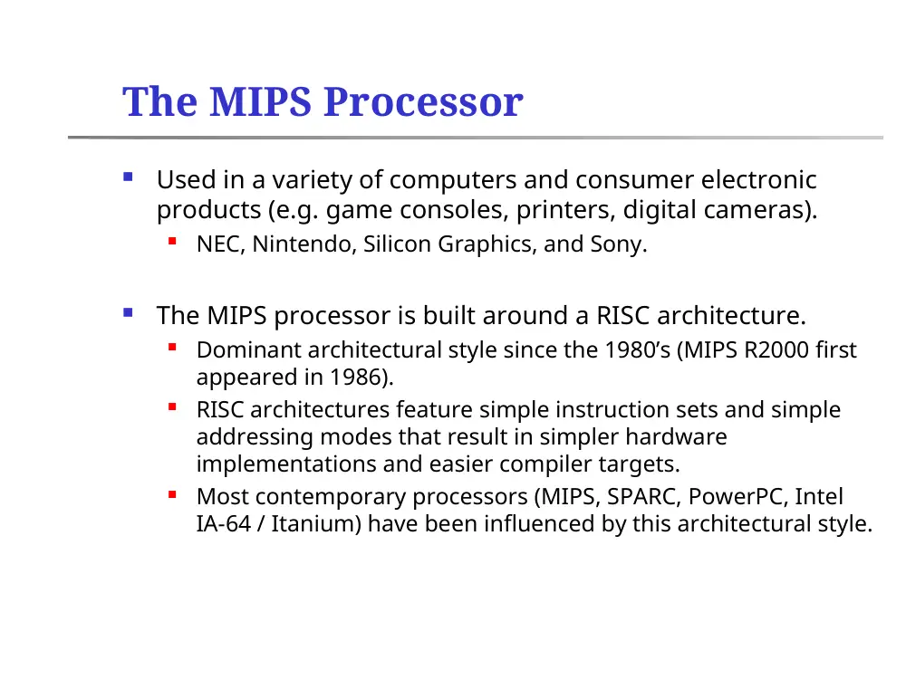
The MIPS Processor
Used in a variety of computers and consumer electronic
products (e.g. game consoles, printers, digital cameras).
NEC, Nintendo, Silicon Graphics, and Sony.
The MIPS processor is built around a RISC architecture.
Dominant architectural style since the 1980’s (MIPS R2000 first
appeared in 1986).
RISC architectures feature simple instruction sets and simple
addressing modes that result in simpler hardware
implementations and easier compiler targets.
Most contemporary processors (MIPS, SPARC, PowerPC, Intel
IA-64 / Itanium) have been influenced by this architectural style.
The MIPS Register Structure
Thirty-two, 32-bit, registers.
Each register has a unique identifier.
Registers are grouped logically to support specific functions.
Name
Number
Use
$zero
0
The constant value 0
$at
1
Assembler temporary (reserved by
Assembler to handle large constants)
$v0 - $v1
2 - 3
Function results and expression
evaluation
$a0 - $a3
4 - 7
Arguments (function parameters)
$t0 - $t7
8 - 15
Temporary values
$s0 - $s7
16 - 23
Saved temporary values
$t8 - $t9
24 - 25
Temporary values
$k0 - $k1
26 - 27
Reserved for OS Kernel
$gp
28
Global pointer
$sp
29
Stack pointer
$fp
30
Frame pointer
$ra
31
Return address
Representing Instructions Inside the
Computer
Instructions are represented as sequences of binary code.
In the MIPS architecture, each instruction is stored as a single
32-bit word. This simplifies the memory interface and the
instruction decode logic.
Some processors (e.g. MC68000, IA-32) support variable-length
instructions.
Instructions are divided into fields, each encoding a part of
the instruction.
Opcode
Source registers
Destination registers
Immediate operands
Etc…
MIPS Instruction Formats
The MIPS uses three instruction formats.
Different formats are needed to encode different types of
instructions (e.g. arithmetic, memory access, branch).
The three formats represent a trade-off between having a
single instruction format and keeping the instruction length
constant.
Opcode
rs
rt
rd
shamt
funct
6 bits
5 bits
5 bits
5 bits
5 bits
6 bits
R-Type
Opcode
rs
rt
address
6 bits
5 bits
5 bits
16 bits
I-Type
Opcode
address
6 bits
26 bits
J-Type
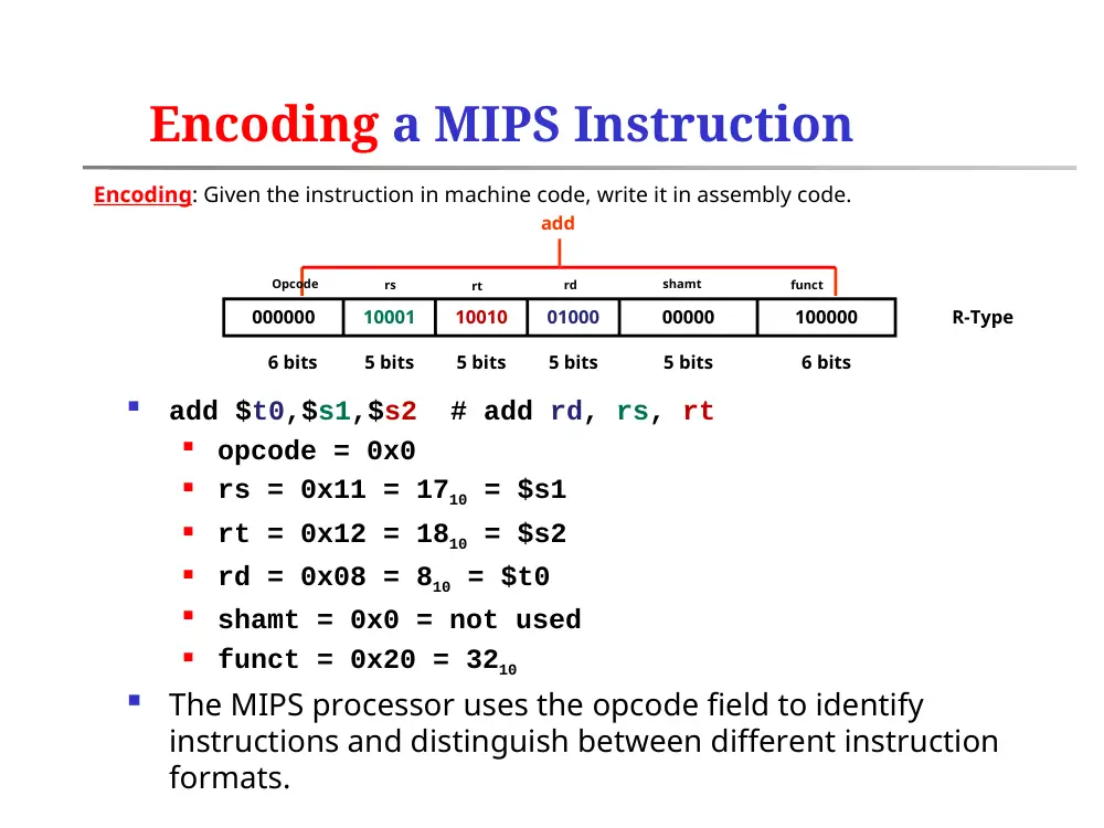
Encoding a MIPS Instruction
add $t0,$s1,$s2 # add rd, rs, rt
opcode = 0x0
rs = 0x11 = 1710 = $s1
rt = 0x12 = 1810 = $s2
rd = 0x08 = 810 = $t0
shamt = 0x0 = not used
funct = 0x20 = 3210
The MIPS processor uses the opcode field to identify
instructions and distinguish between different instruction
formats.
000000
10001
10010
01000
00000
100000
6 bits
5 bits
5 bits
5 bits
5 bits
6 bits
R-Type
add
Encoding: Given the instruction in machine code, write it in assembly code.
Opcode
rs
rt
rd
shamt
funct
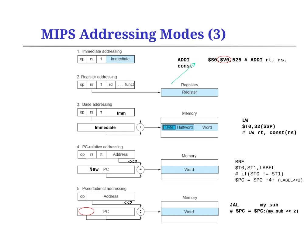
MIPS Addressing Modes
Immediate Addressing
Operand is a 16-bit constant.
Used with I-type instructions.
ADDI
$S0,$V0,525 # ADDI rt, rs, const
Register Addressing
Operand is a register
Used with R-type and I-type instructions.
ADD
$T0,$S0,$S1 # ADD rd, rs, rt
Base or Displacement Addressing
Operand is at a memory location whose address is the sum of a
base register and a constant, 16-bit, offset.
Used with I-type instructions.
LW
$T0,32($SP) # LW rt, const(rs)
Opcode
rs
rt
rd
shamt
funct
6 bits
5 bits
5 bits
5 bits
5 bits
6 bits
R-Type
Opcode
rs
rt
address
6 bits
5 bits
5 bits
16 bits
MIPS Addressing Modes (2)
PC-Relative Addressing
Branch address is the sum of the PC (actually PC+4) and a 16-bit
constant in the instruction.
Constant represents a word offset. When computing the target address,
the offset should first be multiplied by four.
Used with I-type instructions.
BNE
$T0,$T1,LABEL # if($T0 != $T1) $PC = $PC +4+ (LABEL<<2)
Pseudo-direct Addressing
Jump address is the 26 bits (representing a word address) of the
instruction concatenated with the upper bits of the PC (after being
multiplied by four).
Used with J-type instructions.
JAL
my_sub
# $PC = $PC:(my_sub << 2)
Opcode
rs
rt
address
6 bits
5 bits
5 bits
16 bits
Opcode
address
6 bits
26 bits
J-Type
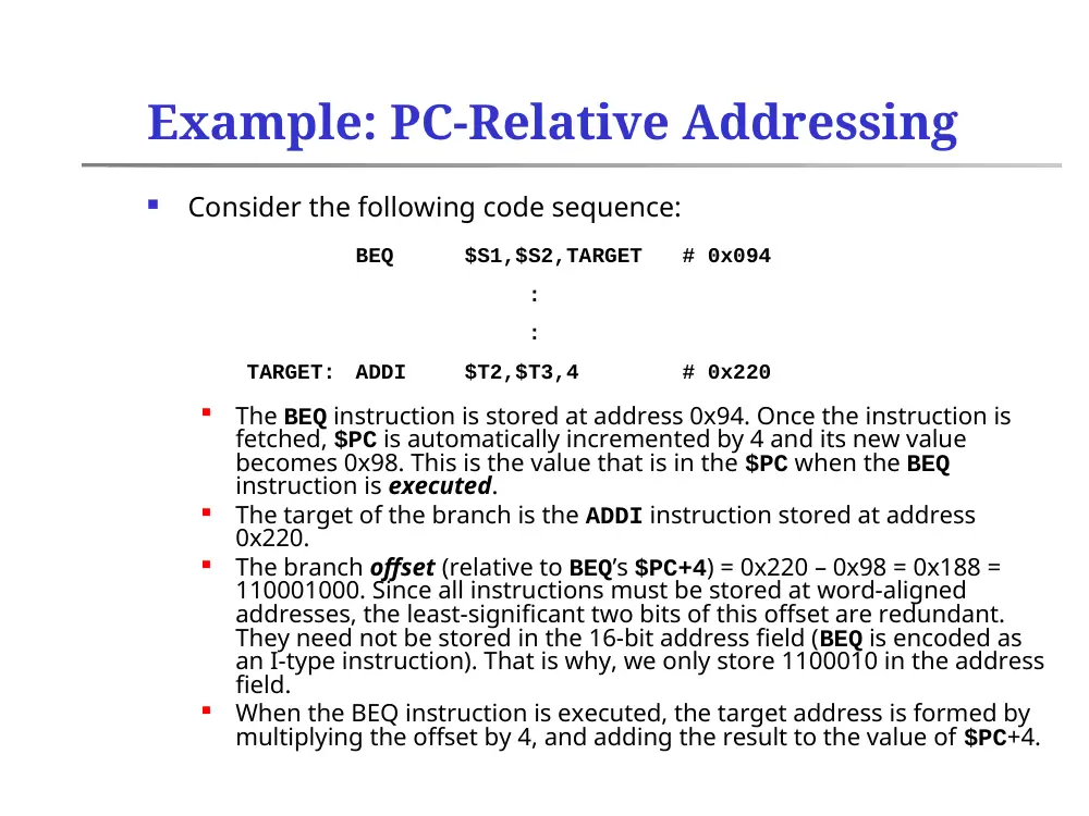
Example: PC-Relative Addressing
Consider the following code sequence:
The BEQ instruction is stored at address 0x94. Once the instruction is
fetched, $PC is automatically incremented by 4 and its new value
becomes 0x98. This is the value that is in the $PC when the BEQ
instruction is executed.
The target of the branch is the ADDI instruction stored at address
0x220.
The branch offset (relative to BEQ’s $PC+4) = 0x220 – 0x98 = 0x188 =
110001000. Since all instructions must be stored at word-aligned
addresses, the least-significant two bits of this offset are redundant.
They need not be stored in the 16-bit address field (BEQ is encoded as
an I-type instruction). That is why, we only store 1100010 in the address
field.
When the BEQ instruction is executed, the target address is formed by
multiplying the offset by 4, and adding the result to the value of $PC+4.
BEQ
$S1,$S2,TARGET
# 0x094
:
:
TARGET:
ADDI
$T2,$T3,4
# 0x220
MIPS Addressing Modes (3)
Immediate
ADDI
$S0,$V0,525 # ADDI rt, rs,
const
Imm
LW
$T0,32($SP)
# LW rt, const(rs)
<<2
New
<<2
BNE
$T0,$T1,LABEL
# if($T0 != $T1)
$PC = $PC +4+ (LABEL<<2)
JAL
my_sub
# $PC = $PC:(my_sub << 2)
Example 2: PC-Relative Addressing
Consider the following sequence of MIPS R2000 assembly instructions:
BNE
$S3,$S4,ELSE
ADD
$S0,$S1,$S2
SUB
$S1,$S3,$S2
J
EXIT
ELSE:
SUB
$S0,$S1,$S2
EXIT:
Provide the instruction encoding (i.e. the machine language equivalent) of the first
MIPS R2000 instruction in the sequence (i.e. BNE $S3, $S4, ELSE) assuming this
instruction is stored at memory address 56BC8644H.
Using the instruction encoding you just wrote, show how the PC gets loaded with the
address of the target instruction.
Opcode
rs
rt
address
6 bits
5 bits
5 bits
16 bits
000101 10011 10100 0000000000000011 (3 words)
BNE $S3 $S4 distance from PC+4 to ELSE
56BC8644
56BC8648
56BC864C
56BC8650
56BC8654
…01010100
-…01001000
…00001100
Example 3: Pseudo-direct Addressing
Decode the following MIPS R2000 machine instruction (i.e.
write the equivalent assembly instruction) assuming the
instruction is stored at address BC45F378H.
00001011111100111111111101010101 machine instr.
J Label assembly instr.
PC 1011 11111100111111111101010101 00
Most significant 4-bit of PC
(Label represents the previous address)