
EECE 312L Notes Experiment 8 Notes, Fall 2013
American University of Beirut · Circuits and Electronics Lab · 7 pages




More EECE 312L files
- Notes Experiment 2 Notes · Fall 2013NotesView
- Notes Experiment 3 Notes · Fall 2013NotesView
- Notes Experiment 11 Notes · Fall 2013NotesView
- Notes Experiment 6 Notes · Fall 2013NotesView
- Notes Experiment 4 Notes · Fall 2013NotesView
- Notes Experiment 5 Notes · Fall 2013NotesView
- Notes Experiment 10 Notes · Fall 2013NotesView
- Notes Experiment 1 Notes · Fall 2013NotesView
Show the text of this notes
Experiment 8
Op-Amp Circuits
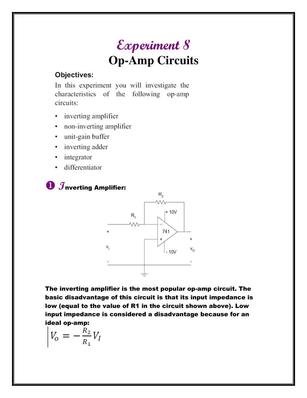
Inverting Amplifier:
The inverting amplifier is the most popular op-amp circuit. The
basic disadvantage of this circuit is that its input impedance is
low (equal to the value of R1 in the circuit shown above). Low
input impedance is considered a disadvantage because for an
ideal op-amp:
Why is a low input impedance considered a disadvantage?
The inverting amplifier is the most popular op- amp circuit. The
basic disadvantage of this circuit is that its input impedance is
low (equal to the value of R1 in the circuit shown above).
Theoretically we have considered that the input voltage of the
op- amp is equal to zero due to high impedance that is Iin=0. Thus
changing the theoretical value of the input voltage would affect
our next calculations. Moreover, we note that the low input
impedance would force high current to flow in the circuit (op-
amp) that would be greater than a certain threshold value (since
impedance and current are inversely proportional). This will
damage the op- amp and will cause heat dissipation in the above
circuit.
The bandwidth of the inverting op-amp: The bandwidth in this
case is equal to the frequency at which the magnitude of the
gain Vo/VI drops to 1/√2 of its low frequency value (which,
theoretically, is R2/R1.)
The absolute value of the gain: |A|= Vo/V1 = R2/R 1. To find a
relation between the low-frequency gain and bandwidth, we refer
to our experimental results:
For gain = 10, bandwidth = 79 KHz
For gain = 4.54, bandwidth = 161.22 KHz
=> When the gain increases the bandwidth decreases.
We conclude that the bandwidth is inversely proportional to the
low-frequency gain.
Notes: Corner frequency is when gain (A=VO/VI) = 0.707 from
its original value
The product between bandwidth and gain is approximately
constant.
****In the experiment we measure V0 peak to peak using the
oscilloscope (measure then read the value on the right of the
screen). The output voltage is 180 degree out of phase with the
input voltage. This is the particularity of an inverting amplifier
which give us an inverted output thus 180 degree phase angle.
Non-Inverting Amplifier:
The non-inverting amplifier offers an advantage over the inverting
configuration in that the input impedance is that of the op-amp
itself (which, ideally, is infinite) rather than R1.
Theoretically for an ideal op-amp:
The bandwidth of the non-inverting op-amp is equal to the
frequency at which the magnitude of the gain drops to of its low
frequency value (which, theoretically, is 1+R2/R1.)
For R1 = 1 KΩ and R2 = 4.7 KΩ, measure the output when the input
is a 200 mV peak-to-peak sinusoidal with variable frequency.
Increase the frequency starting from 1000 Hz until the gain drops
to 0.7071 times its measured low frequency value. Note the value
of this frequency.
******In a non-inverting amplifier the output is with phase with
the input. The phase angle is 0 degree.
We get the value of V0 peak to peak as usual we use measure in
oscilloscope and read peak to peak value.
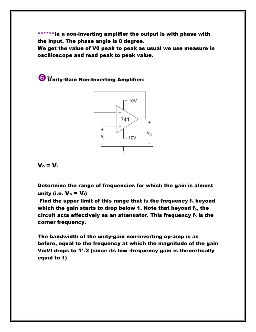
Unity-Gain Non-Inverting Amplifier:
VO = VI
Determine the range of frequencies for which the gain is almost
unity (i.e. VO = VI)
Find the upper limit of this range that is the frequency f0 beyond
which the gain starts to drop below 1. Note that beyond f0, the
circuit acts effectively as an attenuator. This frequency f0 is the
corner frequency.
The bandwidth of the unity-gain non-inverting op-amp is as
before, equal to the frequency at which the magnitude of the gain
Vo/VI drops to 1/√2 (since its low -frequency gain is theoretically
equal to 1)
Integrator:
The fundamental operation of an op-amp integrator is similar to
the inverting amplifier except that the input current is
transferred to a feedback capacitor rather than resistor.
Apply a symmetrical square wave signal at the input. To verify
experimentally that
, we should prove that the peak to- peak output
voltage is equal (in absolute value) to the area enclosed under
the square wave (for 0 < t < T/2 or for T/2 < t < T) divided by the
product RC.
******In the experiment we measured the frequency of the
output signal V0 using measure-then read the frequency.
Also we read the peak to peak value of V0 using the
oscilloscope.
Increase the frequency of the input above 10 KHz, and
observe the output. At what frequency does the output stop
corresponding to the integral of the input (i.e. the output
waveform stops resembling a triangular waveform)? Note that
you may need to increase the peak-to-peak value of the input
voltage to be able to observe the output at high frequencies.
Find out what causes the deterioration in the integration action
of the op-amp in the circuit shown above.
At the value of 20 kHz, the output stops corresponding to the
integral of the input. The output waveform stops looking like a
triangular waveform. Initially it should look like one because of
the integrating property of the circuit. Once we increase the
frequency of the input above 10 KHz and observe the output we
notice that the square wave gets distorted.
The deterioration in the integration action of the op-amp in the
circuit shown above is caused by the high frequency, at which
the capacitor charges and discharges so quickly. So, the
waveforms look like impulses that destroy the integration form of
the output waveform. At high frequencies, the charging and
discharging of the capacitor occurs so fast, that they tend to be
like impulses that distort the waveform pattern.
Differentiator:
Apply a symmetrical triangular wave signal at the input.
To prove experimentally that:
, we should prove that the output voltage level equal,
in absolute value, to the product RC multiplied by the slope of the
triangular input signal.
******Similarly as before in the experiment we measured the
frequency of the output signal V0 using measure-then read the
frequency.
Also we read the peak to peak value of V0 using the oscilloscope.
General Shape of the OP-Amp