
EECE 312L Notes Experiment 9 Notes, Fall 2013
American University of Beirut · Circuits and Electronics Lab · 3 pages
More EECE 312L files
- Notes Experiment 2 Notes · Fall 2013NotesView
- Notes Experiment 3 Notes · Fall 2013NotesView
- Notes Experiment 11 Notes · Fall 2013NotesView
- Notes Experiment 6 Notes · Fall 2013NotesView
- Notes Experiment 4 Notes · Fall 2013NotesView
- Notes Experiment 5 Notes · Fall 2013NotesView
- Notes Experiment 10 Notes · Fall 2013NotesView
- Notes Experiment 1 Notes · Fall 2013NotesView
Show the text of this notes
Experiment 9
Transformers
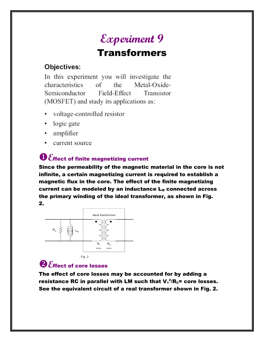
Effect of finite magnetizing current
Since the permeability of the magnetic material in the core is not
infinite, a certain magnetizing current is required to establish a
magnetic flux in the core. The effect of the finite magnetizing
current can be modeled by an inductance LM connected across
the primary winding of the ideal transformer, as shown in Fig.
2.
Effect of core losses
The effect of core losses may be accounted for by adding a
resistance RC in parallel with LM such that V1
2/RC= core losses.
See the equivalent circuit of a real transformer shown in Fig. 2.
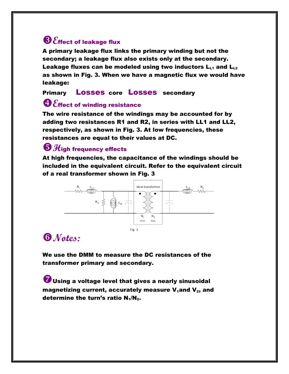
Effect of leakage flux
A primary leakage flux links the primary winding but not the
secondary; a leakage flux also exists only at the secondary.
Leakage fluxes can be modeled using two inductors LL1 and LL2
as shown in Fig. 3. When we have a magnetic flux we would have
leakage:
Primary Losses core Losses secondary
Effect of winding resistance
The wire resistance of the windings may be accounted for by
adding two resistances R1 and R2, in series with LL1 and LL2,
respectively, as shown in Fig. 3. At low frequencies, these
resistances are equal to their values at DC.
High frequency effects
At high frequencies, the capacitance of the windings should be
included in the equivalent circuit. Refer to the equivalent circuit
of a real transformer shown in Fig. 3
Notes:
We use the DMM to measure the DC resistances of the
transformer primary and secondary.
Using a voltage level that gives a nearly sinusoidal
magnetizing current, accurately measure V1and V2, and
determine the turn’s ratio N1/N2.
Increase the value of RS to 100 Ohms. Apply a sinusoidal
voltage of 100 Hz, adjusting the voltage so that the magnetizing
current is nearly sinusoidal. Measure the magnitude and phase
shift of this current with respect to V1.
Connect a 100 Ohm resistor at the secondary of the
transformer. Determine the bandwidth of the transformer with
the load connected: find the lower cutoff frequency f1 and the
upper cutoff frequency f2. The cutoff frequencies are the
frequencies at which the output voltage is 0.7071 times its value
at mid frequencies. Make sure that the magnetizing current
remains sinusoidal at all frequencies.
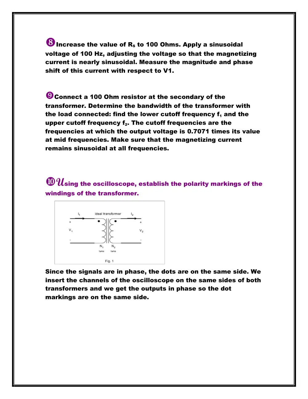
Using the oscilloscope, establish the polarity markings of the
windings of the transformer.
Since the signals are in phase, the dots are on the same side. We
insert the channels of the oscilloscope on the same sides of both
transformers and we get the outputs in phase so the dot
markings are on the same side.