
EECE 320 Lecture 21, Fall 2011
American University of Beirut · Digital Systems Design · 13 pages · Prof. Ali Chehab
Showing the first 10 of 13 pages. Download the PDF to see all of it.
More EECE 320 files
Show the text of this lab
EECE 320 L21: Combinational Logic design Practices 1
Chehab, AUB, 2003
EECE 320
Digital Systems Design
Lecture 21:
Sequential Logic Design
Principles
Ali Chehab
EECE 320 L21: Combinational Logic design Practices 2
Chehab, AUB, 2003
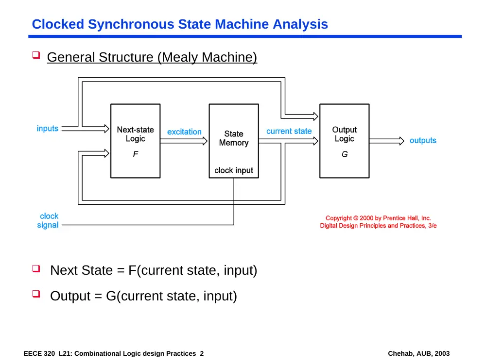
Clocked Synchronous State Machine Analysis
General Structure (Mealy Machine)
Next State = F(current state, input)
Output = G(current state, input)
EECE 320 L21: Combinational Logic design Practices 3
Chehab, AUB, 2003
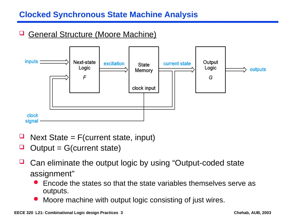
Clocked Synchronous State Machine Analysis
General Structure (Moore Machine)
Next State = F(current state, input)
Output = G(current state)
Can eliminate the output logic by using “Output-coded state
assignment”
Encode the states so that the state variables themselves serve as
outputs.
Moore machine with output logic consisting of just wires.
EECE 320 L21: Combinational Logic design Practices 4
Chehab, AUB, 2003
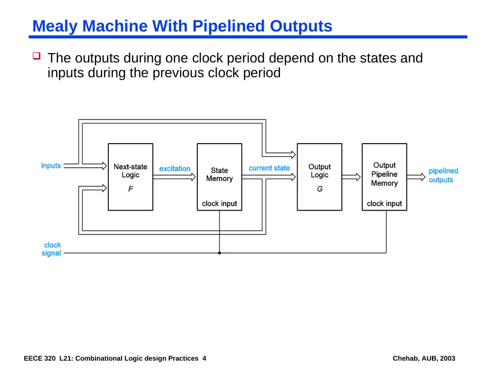
Mealy Machine With Pipelined Outputs
The outputs during one clock period depend on the states and
inputs during the previous clock period
EECE 320 L21: Combinational Logic design Practices 5
Chehab, AUB, 2003
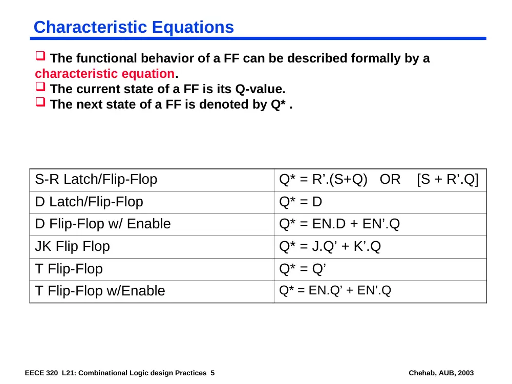
Characteristic Equations
S-R Latch/Flip-Flop
Q* = R’.(S+Q) OR [S + R’.Q]
D Latch/Flip-Flop
Q* = D
D Flip-Flop w/ Enable
Q* = EN.D + EN’.Q
JK Flip Flop
Q* = J.Q’ + K’.Q
T Flip-Flop
Q* = Q’
T Flip-Flop w/Enable
Q* = EN.Q’ + EN’.Q
The functional behavior of a FF can be described formally by a
characteristic equation.
The current state of a FF is its Q-value.
The next state of a FF is denoted by Q* .
EECE 320 L21: Combinational Logic design Practices 6
Chehab, AUB, 2003
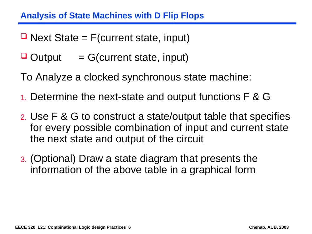
Analysis of State Machines with D Flip Flops
Next State = F(current state, input)
Output = G(current state, input)
To Analyze a clocked synchronous state machine:
1. Determine the next-state and output functions F & G
2. Use F & G to construct a state/output table that specifies
for every possible combination of input and current state
the next state and output of the circuit
3. (Optional) Draw a state diagram that presents the
information of the above table in a graphical form
EECE 320 L21: Combinational Logic design Practices 7
Chehab, AUB, 2003
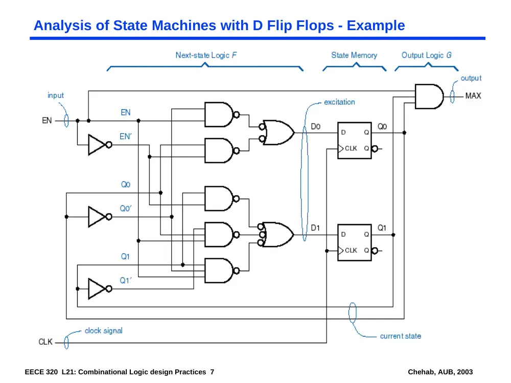
Analysis of State Machines with D Flip Flops - Example
EECE 320 L21: Combinational Logic design Practices 8
Chehab, AUB, 2003
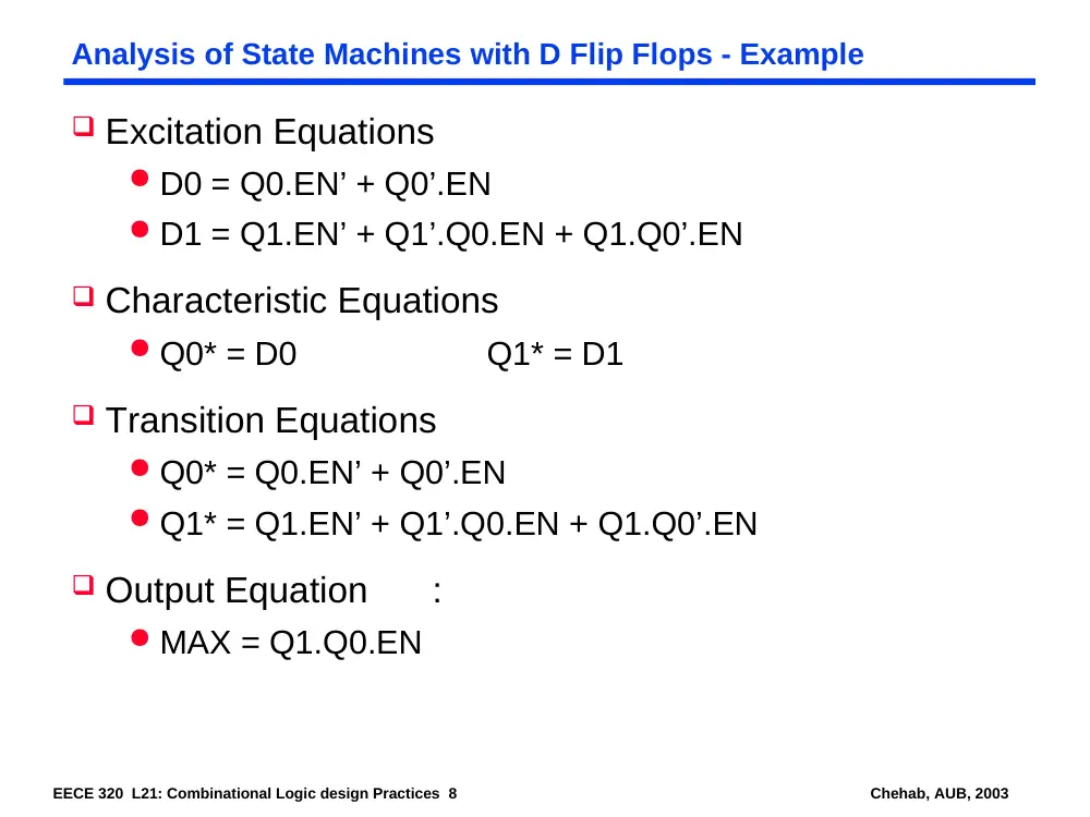
Analysis of State Machines with D Flip Flops - Example
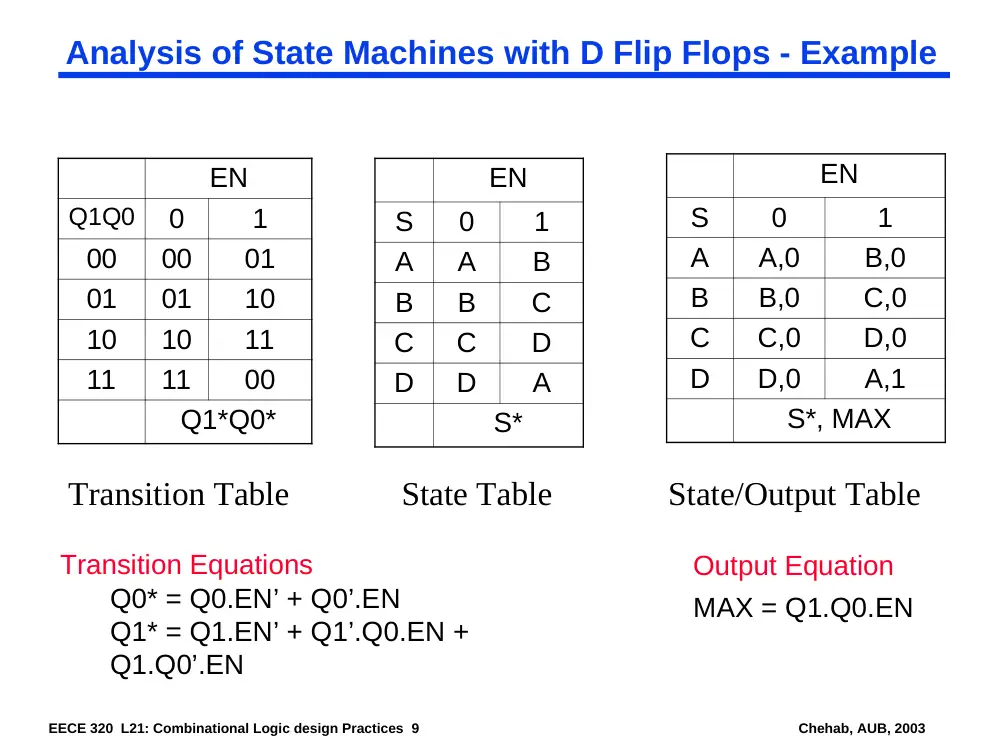
Excitation Equations
D0 = Q0.EN’ + Q0’.EN
D1 = Q1.EN’ + Q1’.Q0.EN + Q1.Q0’.EN
Characteristic Equations
Q0* = D0
Q1* = D1
Transition Equations
Q0* = Q0.EN’ + Q0’.EN
Q1* = Q1.EN’ + Q1’.Q0.EN + Q1.Q0’.EN
Output Equation
:
MAX = Q1.Q0.EN
EECE 320 L21: Combinational Logic design Practices 9
Chehab, AUB, 2003
Analysis of State Machines with D Flip Flops - Example
EN
Q1Q0
0
1
00
00
01
01
01
10
10
10
11
11
11
00
Q1*Q0*
EN
S
0
1
A
A
B
B
B
C
C
C
D
D
D
A
S*
Transition Table
EN
S
0
1
A
A,0
B,0
B
B,0
C,0
C
C,0
D,0
D
D,0
A,1
S*, MAX
State Table
State/Output Table
Transition Equations
Q0* = Q0.EN’ + Q0’.EN
Q1* = Q1.EN’ + Q1’.Q0.EN +
Q1.Q0’.EN
Output Equation
MAX = Q1.Q0.EN
EECE 320 L21: Combinational Logic design Practices 10
Chehab, AUB, 2003
Analysis of State Machines with D Flip Flops - Example
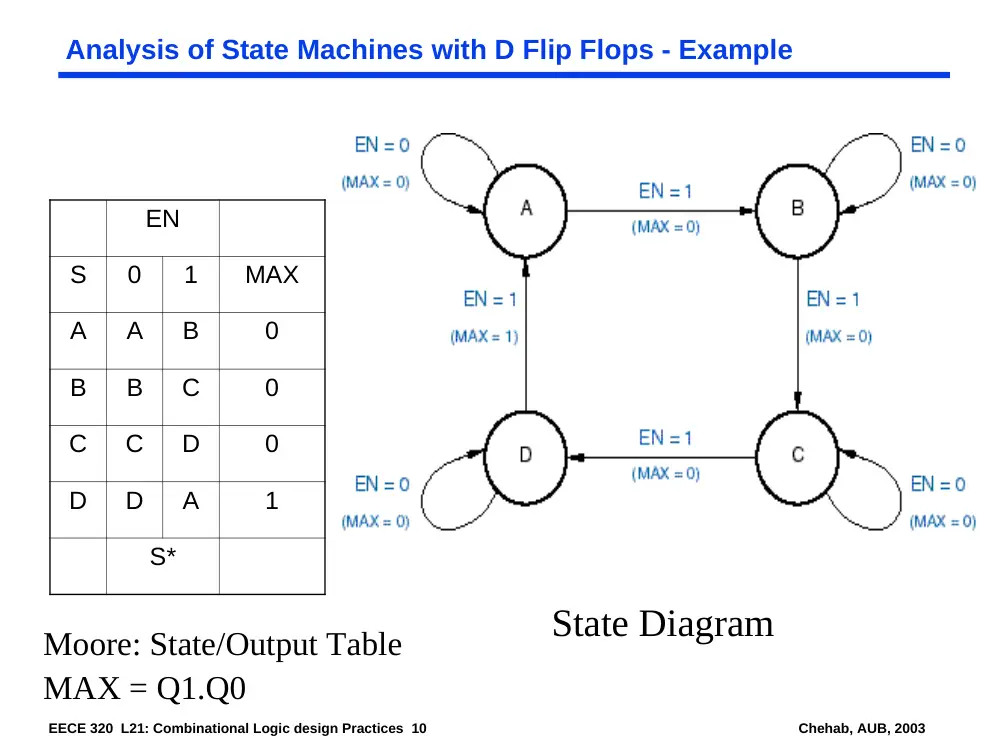
EN
S
0
1
MAX
A
A
B
0
B
B
C
0
C
C
D
0
D
D
A
1
S*
Moore: State/Output Table
MAX = Q1.Q0
State Diagram
EECE 320 L21: Combinational Logic design Practices 11
Chehab, AUB, 2003
Analysis of State Machines with D Flip Flops - Example
EN
S
0
1
A
A,0
B,0
B
B,0
C,0
C
C,0
D,0
D
D,0
A,1
S*, MAX
EECE 320 L21: Combinational Logic design Practices 12
Chehab, AUB, 2003
FSM Analysis Example
D1 Q1
>CLK
D2 Q2
>CLK
EECE 320 L21: Combinational Logic design Practices 13
Chehab, AUB, 2003
Next Lecture and Reminders
Next lecture
Reminders