
EECE 320 Lecture 23, Fall 2011
American University of Beirut · Digital Systems Design · 18 pages · Prof. Ali Chehab
Showing the first 10 of 18 pages. Download the PDF to see all of it.
More EECE 320 files
Show the text of this lab
EECE 320 L23: Combinational Logic design Practices 1
Chehab, AUB, 2003
EECE 320
Digital Systems Design
Lecture 23:
Sequential Logic Design
Principles
Ali Chehab
EECE 320 L23: Combinational Logic design Practices 2
Chehab, AUB, 2003
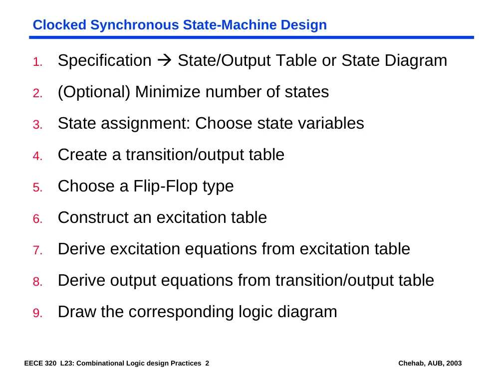
Clocked Synchronous State-Machine Design
1.
Specification State/Output Table or State Diagram
2.
(Optional) Minimize number of states
3.
State assignment: Choose state variables
4.
Create a transition/output table
5.
Choose a Flip-Flop type
6.
Construct an excitation table
7.
Derive excitation equations from excitation table
8.
Derive output equations from transition/output table
9.
Draw the corresponding logic diagram
EECE 320 L23: Combinational Logic design Practices 3
Chehab, AUB, 2003
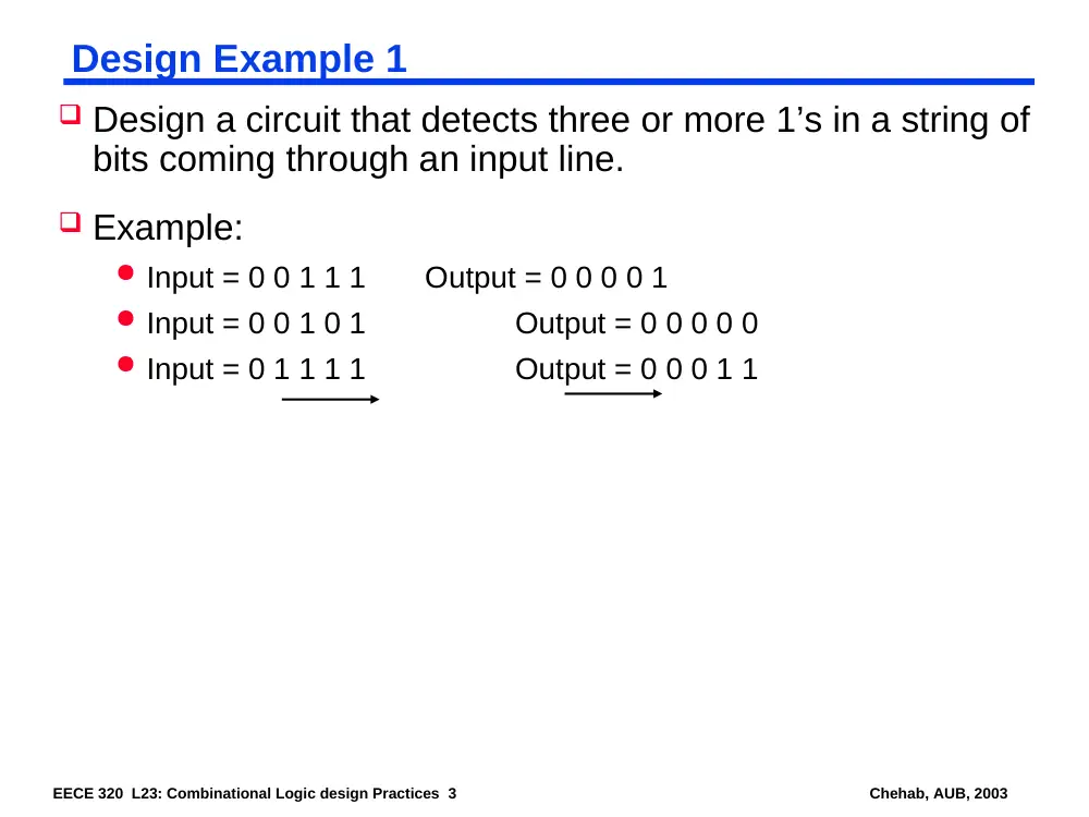
Design Example 1
Design a circuit that detects three or more 1’s in a string of
bits coming through an input line.
Example:
Input = 0 0 1 1 1 Output = 0 0 0 0 1
Input = 0 0 1 0 1
Output = 0 0 0 0 0
Input = 0 1 1 1 1
Output = 0 0 0 1 1
EECE 320 L23: Combinational Logic design Practices 4
Chehab, AUB, 2003
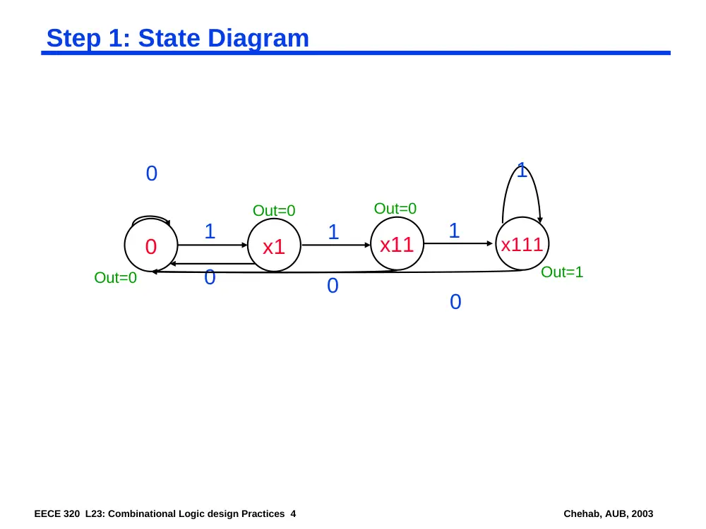
Step 1: State Diagram
0
x1
x11
x111
0
1
0
1
0
1
1
0
Out=0
Out=0
Out=0
Out=1
EECE 320 L23: Combinational Logic design Practices 5
Chehab, AUB, 2003
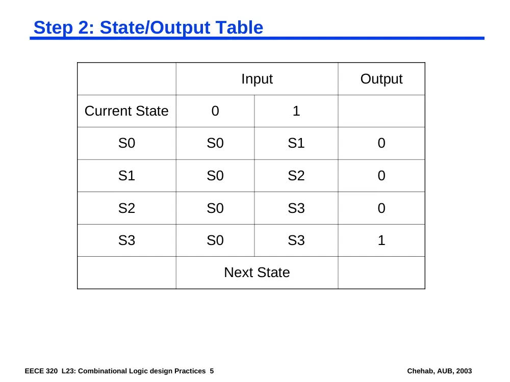
Step 2: State/Output Table
Input
Output
Current State
0
1
S0
S0
S1
0
S1
S0
S2
0
S2
S0
S3
0
S3
S0
S3
1
Next State
EECE 320 L23: Combinational Logic design Practices 6
Chehab, AUB, 2003
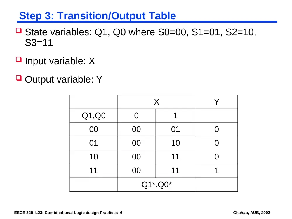
Step 3: Transition/Output Table
X
Y
Q1,Q0
0
1
00
00
01
0
01
00
10
0
10
00
11
0
11
00
11
1
Q1*,Q0*
State variables: Q1, Q0 where S0=00, S1=01, S2=10,
S3=11
Input variable: X
Output variable: Y
EECE 320 L23: Combinational Logic design Practices 7
Chehab, AUB, 2003
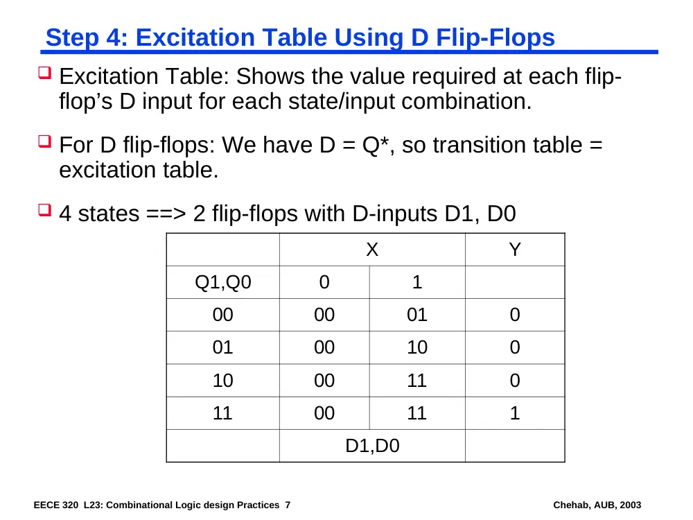
Step 4: Excitation Table Using D Flip-Flops
X
Y
Q1,Q0
0
1
00
00
01
0
01
00
10
0
10
00
11
0
11
00
11
1
D1,D0
Excitation Table: Shows the value required at each flip-
flop’s D input for each state/input combination.
For D flip-flops: We have D = Q*, so transition table =
excitation table.
4 states ==> 2 flip-flops with D-inputs D1, D0
EECE 320 L23: Combinational Logic design Practices 8
Chehab, AUB, 2003
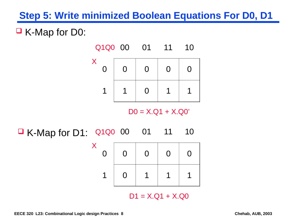
Step 5: Write minimized Boolean Equations For D0, D1
K-Map for D0:
00
01
11
10
0
0
0
0
0
1
1
0
1
1
X
Q1Q0
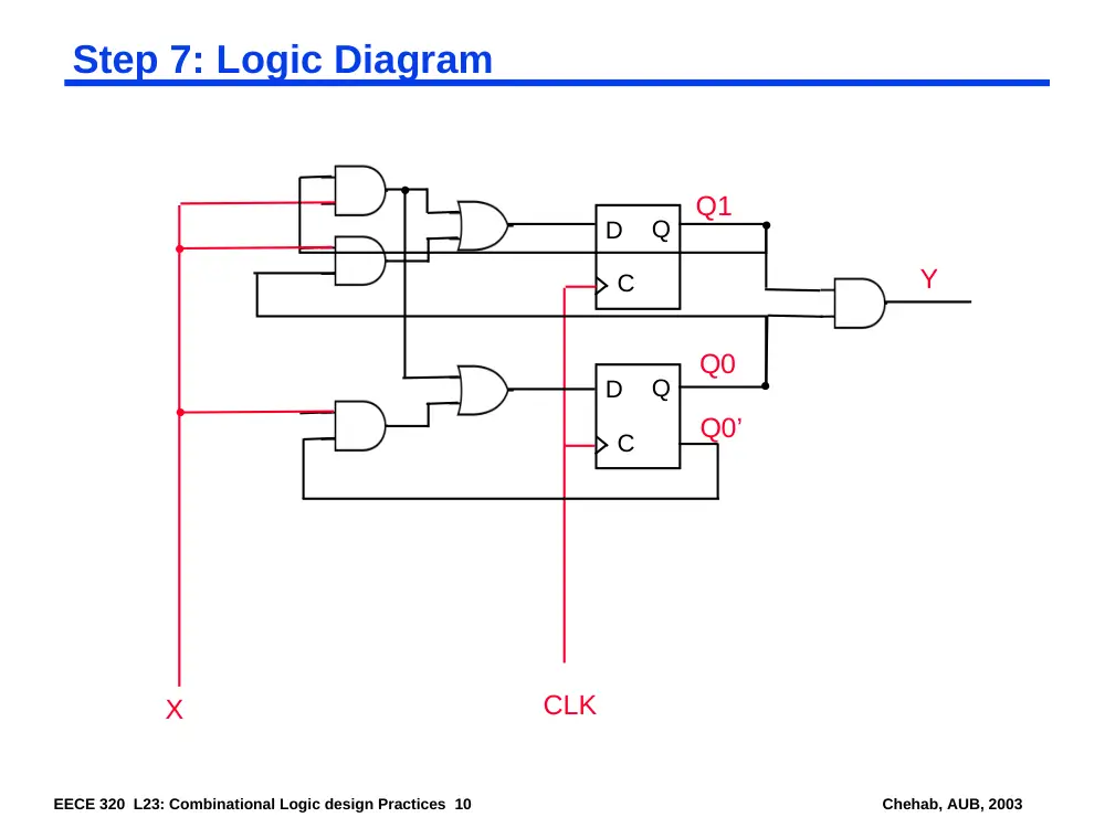
D0 = X.Q1 + X.Q0’
K-Map for D1:
00
01
11
10
0
0
0
0
0
1
0
1
1
1
X
Q1Q0
D1 = X.Q1 + X.Q0
EECE 320 L23: Combinational Logic design Practices 9
Chehab, AUB, 2003
Step 6: Output Equation
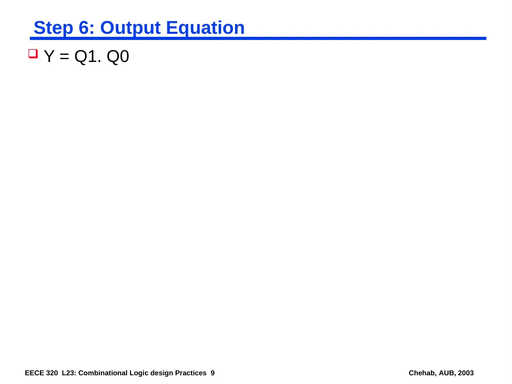
Y = Q1. Q0
EECE 320 L23: Combinational Logic design Practices 10
Chehab, AUB, 2003
Step 7: Logic Diagram
D
C
Q
D
C
Q
Q1
Q0
X
CLK
Q0’
Y
EECE 320 L23: Combinational Logic design Practices 11
Chehab, AUB, 2003
State-Machine Design Example
Two inputs A and B, and one output Z
Z = 1 if:
A had the same values for the previous 2 clock ticks
B has been 1 since last time first condition was true
Otherwise Z = 0
EECE 320 L23: Combinational Logic design Practices 12
Chehab, AUB, 2003
State-Machine Design Example
Evolution of a State Table
EECE 320 L23: Combinational Logic design Practices 13
Chehab, AUB, 2003
State-Machine Design Example
Evolution of a State Table
EECE 320 L23: Combinational Logic design Practices 14
Chehab, AUB, 2003
State-Machine Design Example
State Minimization
Identify equivalent states
2 states S1 and S2 are equivalent if:
S1 and S2 produce the same values at the output
For each input combination, S1 and s2 lead to the same next state
OK00 OKA0
OK11 OKA1
EECE 320 L23: Combinational Logic design Practices 15
Chehab, AUB, 2003
State-Machine Design Example
State Assignment
How many binary variables are needed to represent all
states? With s states, we need n variables: n = log2s.
For s=5, n=3. We need 3 flip-flops => 8 states, with 3 unused.
Assign specific combinations to named states:
Choose an easy initial state: all 0’s or all 1’s
Minimize # of state variables changes on each
transition
Decompose the set of state variables into individual
bits or fields having defined meanings with respect to
inputs or outputs
EECE 320 L23: Combinational Logic design Practices 16
Chehab, AUB, 2003
State-Machine Design Example
State Assignment
One-hot encoding uses 1 flip-flop per state, hence more flip-flops
but simpler excitation equations
For unused states choose between min. risk or min. cost
State
Name
Simplest
Q1 – Q3
Decomposed
Q1 – Q3
One-hot
Q1 – Q5
Almost 1-hot
Q1 – Q4
INIT
000
000
00001
0000
A0
001
100
00010
0001
A1
010
101
00100
0010
OK0
011
110
01000
0100
OK1
100
111
10000
1000
EECE 320 L23: Combinational Logic design Practices 17
Chehab, AUB, 2003
State-Machine Design Example
Synthesis Using D Flip-Flops
AB
S
00
01
11
10
Z
INIT
A0
A0
A1
A1
0
A0
OK0
OK0
A1
A1
0
A1
A0
A0
OK1
OK1
0
OK0
OK0
OK0
OK1
A1
1
OK1
A0
OK0
OK1
OK1
1
S*
Decomposed Assignment
AB
Q1Q2Q3
00
01
11
10
Z
000
100
100
101
101
0
100
110
110
101
101
0
101
100
100
111
111
0
110
110
110
111
101
1
111
100
110
111
111
1
Q1*Q2*Q3*
Transition/Output Table
EECE 320 L23: Combinational Logic design Practices 18
Chehab, AUB, 2003
State-Machine Design Example
Synthesis Using D Flip-Flops
AB
Q1Q2Q3
00
01
11
10
Z
000
100
100
101
101
0
100
110
110
101
101
0
101
100
100
111
111
0
110
110
110
111
101
1
111
100
110
111
111
1
D1D2D3
Excitation/Output Table
D = Q* for D Flip-Flop
Excitation and Transition
tables are the same, which is
not the case for other flip-
flop types.
Excitation table equivalent to
truth table for 3 functions
(D1, D2, D3) of 5 variables
(A, B, Q1, Q2, Q3)
Karnaugh maps.