
EECE 320 Lecture 25, Fall 2011
American University of Beirut · Digital Systems Design · 12 pages · Prof. Ali Chehab


Showing the first 10 of 12 pages. Download the PDF to see all of it.
More EECE 320 files
Show the text of this lab
EECE 320 L25: Combinational Logic design Practices 1
Chehab, AUB, 2003
EECE 320
Digital Systems Design
Lecture 25:
Sequential Logic Design
Principles
Ali Chehab
EECE 320 L25: Combinational Logic design Practices 2
Chehab, AUB, 2003
State-Machine Design using J-K Flip-Flops
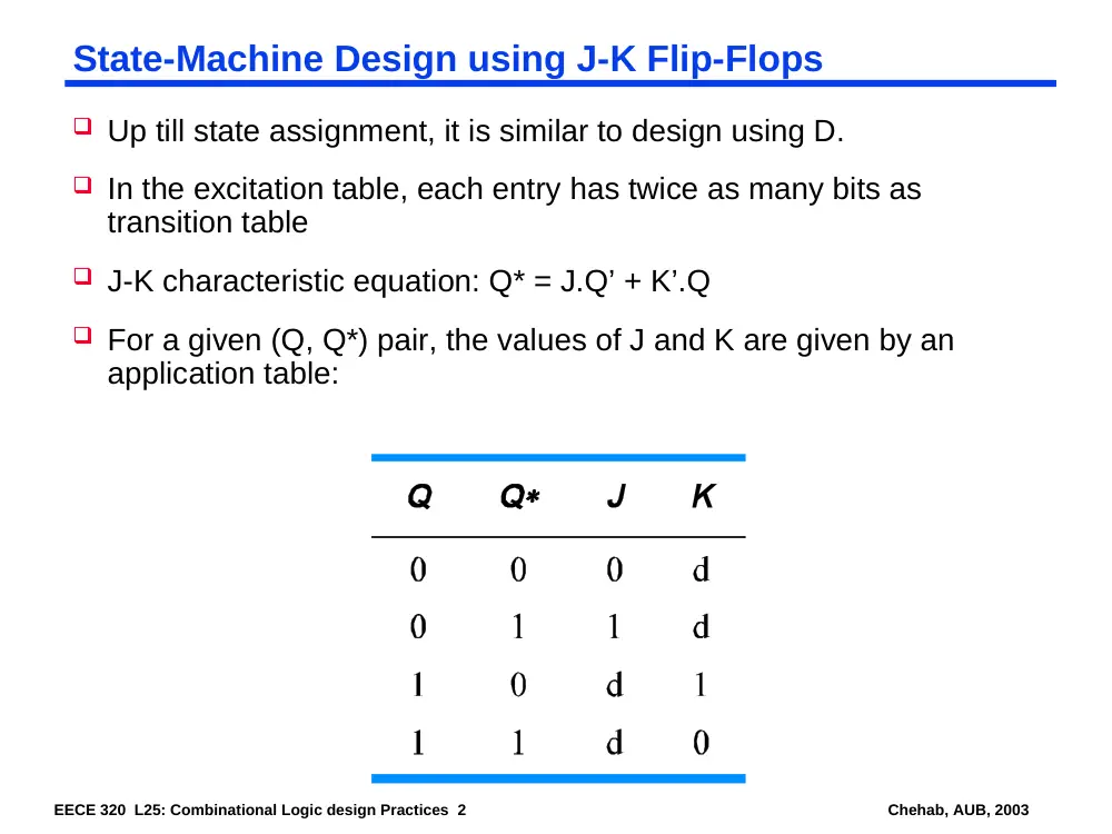
Up till state assignment, it is similar to design using D.
In the excitation table, each entry has twice as many bits as
transition table
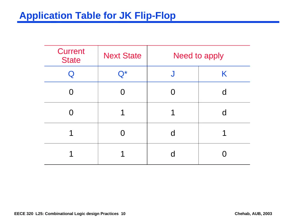
J-K characteristic equation: Q* = J.Q’ + K’.Q
For a given (Q, Q*) pair, the values of J and K are given by an
application table:
EECE 320 L25: Combinational Logic design Practices 3
Chehab, AUB, 2003
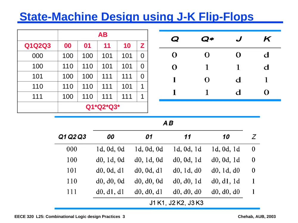
State-Machine Design using J-K Flip-Flops
AB
Q1Q2Q3
00
01
11
10
Z
000
100
100
101
101
0
100
110
110
101
101
0
101
100
100
111
111
0
110
110
110
111
101
1
111
100
110
111
111
1
Q1*Q2*Q3*
EECE 320 L25: Combinational Logic design Practices 4
Chehab, AUB, 2003
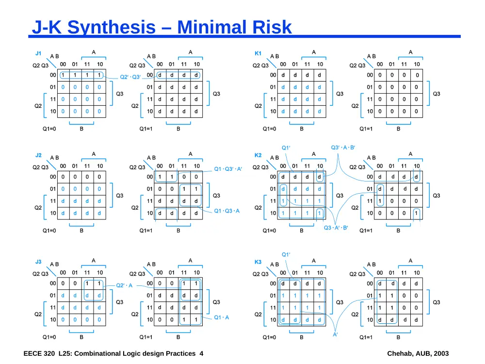
J-K Synthesis – Minimal Risk
EECE 320 L25: Combinational Logic design Practices 5
Chehab, AUB, 2003
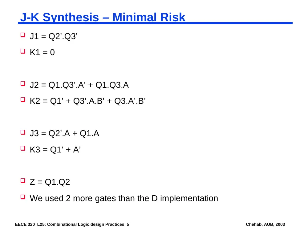
J-K Synthesis – Minimal Risk
J1 = Q2’.Q3’
K1 = 0
J2 = Q1.Q3’.A’ + Q1.Q3.A
K2 = Q1’ + Q3’.A.B’ + Q3.A’.B’
J3 = Q2’.A + Q1.A
K3 = Q1’ + A’
Z = Q1.Q2
We used 2 more gates than the D implementation
EECE 320 L25: Combinational Logic design Practices 6
Chehab, AUB, 2003
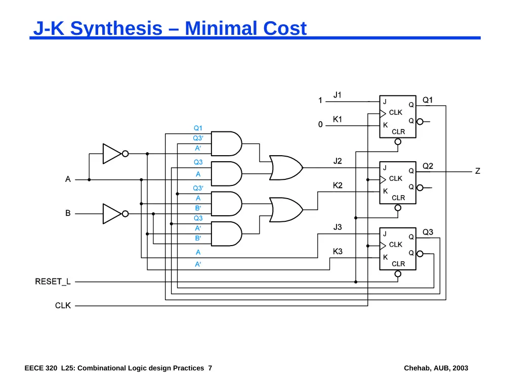
J-K Synthesis – Minimal Cost
We place don’t-cares in empty entries
J1 = 1
K1 = 0
J2 = Q1.Q3’.A’+ Q3.A
K2 = Q3’.A.B’ + Q3.A’.B’
J3 = A
K3 = A’
Z = Q2
We used 2 more gates than the D implementation
EECE 320 L25: Combinational Logic design Practices 7
Chehab, AUB, 2003
J-K Synthesis – Minimal Cost
EECE 320 L25: Combinational Logic design Practices 8
Chehab, AUB, 2003
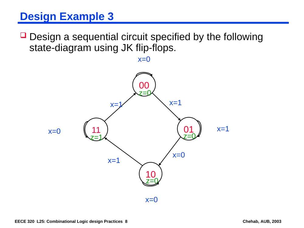
Design Example 3
Design a sequential circuit specified by the following
state-diagram using JK flip-flops.
00
01
10
11
x=0
x=1
x=1
x=0
x=0
x=1
x=0
x=1
z=0
z=0
z=0
z=1
EECE 320 L25: Combinational Logic design Practices 9
Chehab, AUB, 2003
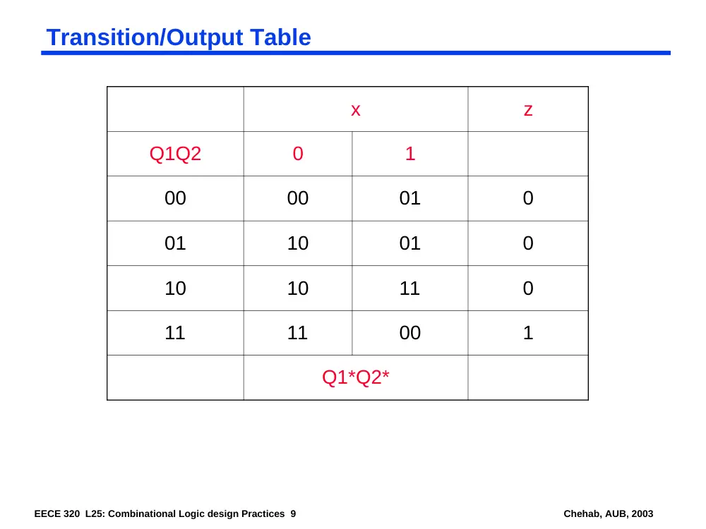
Transition/Output Table
x
z
Q1Q2
0
1
00
00
01
0
01
10
01
0
10
10
11
0
11
11
00
1
Q1*Q2*
EECE 320 L25: Combinational Logic design Practices 10
Chehab, AUB, 2003
Application Table for JK Flip-Flop
Current
State
Next State
Need to apply
Q
Q*
J
K
0
0
0
d
0
1
1
d
1
0
d
1
1
1
d
0
EECE 320 L25: Combinational Logic design Practices 11
Chehab, AUB, 2003
Excitation/Output Table
x
z
Q1Q2
0
1
00
0d, 0d
0d, 1d
0
01
1d, d1
0d, d0
0
10
d0, 0d
d0, 1d
0
11
d0, d0
d1, d1
1
J1K1, J2K2
EECE 320 L25: Combinational Logic design Practices 12
Chehab, AUB, 2003
Excitation Maps
0
1
d
d
0
0
d
d
00
01
11
10
0
1
J1
J1 = x’.Q2
x
Q1Q2
d
d
0
0
d
d
1
0
00
01
11
10
0
1
K1
K1 = x.Q2
x
Q1Q2
0
d
d
0
1
d
d
1
00
01
11
10
0
1
J2
J2 = x
x
Q1Q2
d
1
0
d
d
0
1
d
00
01
11
10
0
1
K2
K2 = x’.Q1’ + x.Q1
= x XNOR Q1
x
Q1Q2