
EECE 320 Lecture 34, Fall 2011
American University of Beirut · Digital Systems Design · 27 pages · Prof. Ali Chehab
Showing the first 10 of 27 pages. Download the PDF to see all of it.
More EECE 320 files
Show the text of this lab
EECE 320 -- Fall 2003
Chehab, American University of Beirut, 2003
Sequential Arithmetic Circuits 1
EECE 320: Digital Systems Design
Lectures 34
Iterative/Sequential Arithmetic Circuits
Ali Chehab
EECE 320 -- Fall 2003
Chehab, American University of Beirut, 2003
Sequential Arithmetic Circuits 2
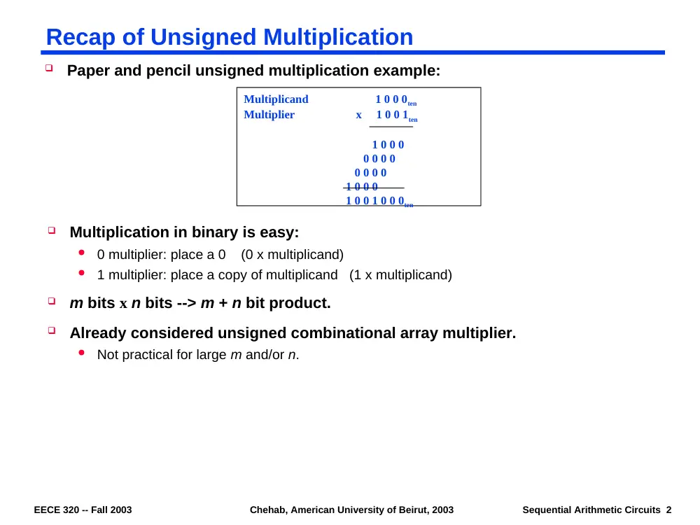
Recap of Unsigned Multiplication
Paper and pencil unsigned multiplication example:
Multiplication in binary is easy:
0 multiplier: place a 0 (0 x multiplicand)
1 multiplier: place a copy of multiplicand (1 x multiplicand)
m bits x n bits --> m + n bit product.
Already considered unsigned combinational array multiplier.
Not practical for large m and/or n.
Multiplicand 1 0 0 0ten
Multiplier x 1 0 0 1ten
1 0 0 0
0 0 0 0
0 0 0 0
1 0 0 0
1 0 0 1 0 0 0ten
EECE 320 -- Fall 2003
Chehab, American University of Beirut, 2003
Sequential Arithmetic Circuits 3
Sequential Multiplier - I
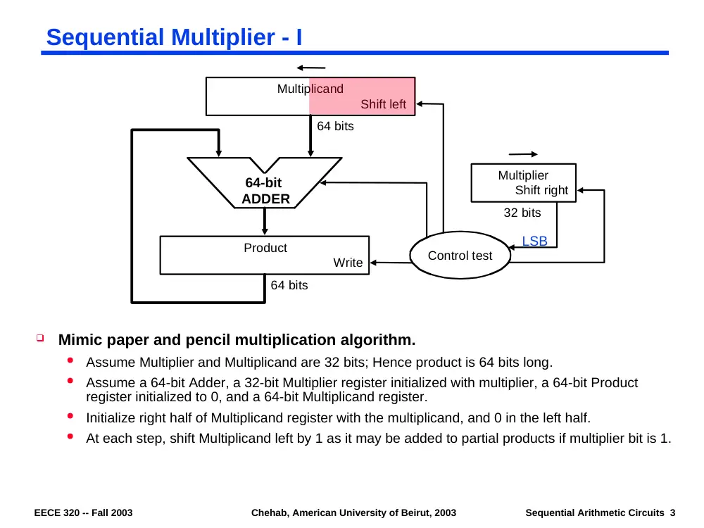
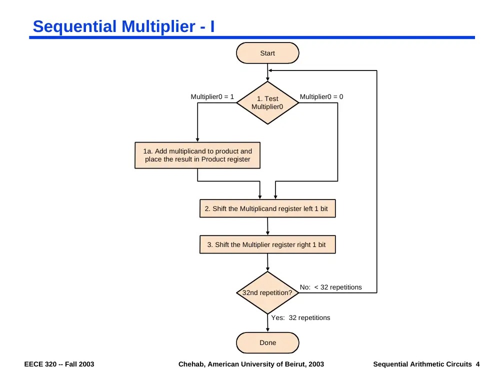
Mimic paper and pencil multiplication algorithm.
Assume Multiplier and Multiplicand are 32 bits; Hence product is 64 bits long.
Assume a 64-bit Adder, a 32-bit Multiplier register initialized with multiplier, a 64-bit Product
register initialized to 0, and a 64-bit Multiplicand register.
Initialize right half of Multiplicand register with the multiplicand, and 0 in the left half.
At each step, shift Multiplicand left by 1 as it may be added to partial products if multiplier bit is 1.
64-bit ALU
Control test
Multiplier
Shift right
Product
Write
Multiplicand
Shift left
64 bits
64 bits
32 bits
LSB
ADDER
64-bit
EECE 320 -- Fall 2003
Chehab, American University of Beirut, 2003
Sequential Arithmetic Circuits 4
Sequential Multiplier - I
Done
1. Test
Multiplier0
1a. Add multiplicand to product and
place the result in Product register
2. Shift the Multiplicand register left 1 bit
3. Shift the Multiplier register right 1 bit
32nd repetition?
Start
Multiplier0 = 0
Multiplier0 = 1
No: < 32 repetitions
Yes: 32 repetitions
EECE 320 -- Fall 2003
Chehab, American University of Beirut, 2003
Sequential Arithmetic Circuits 5
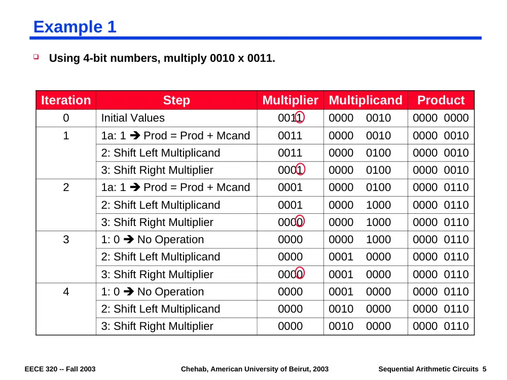
Example 1
Using 4-bit numbers, multiply 0010 x 0011.
Iteration
Step
Multiplier
Multiplicand
Product
0
Initial Values
0011
0000 0010
0000 0000
1
1a: 1 Prod = Prod + Mcand
0011
0000 0010
0000 0010
2: Shift Left Multiplicand
0011
0000 0100
0000 0010
3: Shift Right Multiplier
0001
0000 0100
0000 0010
2
1a: 1 Prod = Prod + Mcand
0001
0000 0100
0000 0110
2: Shift Left Multiplicand
0001
0000 1000
0000 0110
3: Shift Right Multiplier
0000
0000 1000
0000 0110
3
1: 0 No Operation
0000
0000 1000
0000 0110
2: Shift Left Multiplicand
0000
0001 0000
0000 0110
3: Shift Right Multiplier
0000
0001 0000
0000 0110
4
1: 0 No Operation
0000
0001 0000
0000 0110
2: Shift Left Multiplicand
0000
0010 0000
0000 0110
3: Shift Right Multiplier
0000
0010 0000
0000 0110
EECE 320 -- Fall 2003
Chehab, American University of Beirut, 2003
Sequential Arithmetic Circuits 6
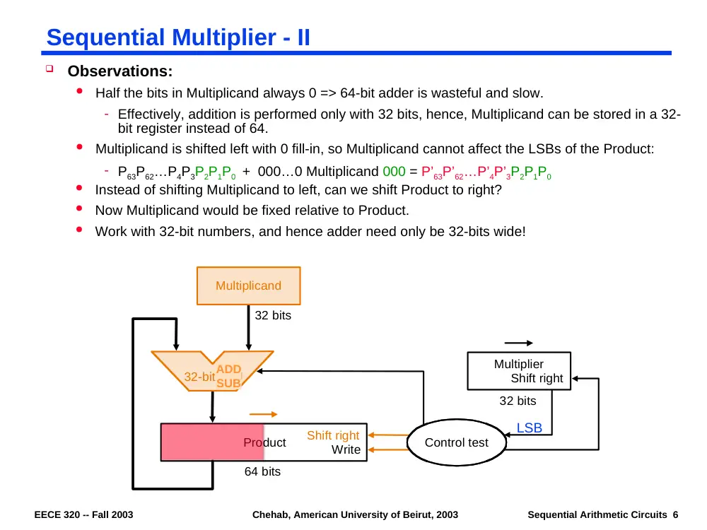
Sequential Multiplier - II
Observations:
Half the bits in Multiplicand always 0 => 64-bit adder is wasteful and slow.
- Effectively, addition is performed only with 32 bits, hence, Multiplicand can be stored in a 32-
bit register instead of 64.
Multiplicand is shifted left with 0 fill-in, so Multiplicand cannot affect the LSBs of the Product:
- P63P62…P4P3P2P1P0 + 000…0 Multiplicand 000 = P’63P’62…P’4P’3P2P1P0
Instead of shifting Multiplicand to left, can we shift Product to right?
Now Multiplicand would be fixed relative to Product.
Work with 32-bit numbers, and hence adder need only be 32-bits wide!
Multiplier
Shift right
Write
32 bits
64 bits
32 bits
Shift right
Multiplicand
32-bit ALU
Product
Control test
LSB
ADD
SUB
EECE 320 -- Fall 2003
Chehab, American University of Beirut, 2003
Sequential Arithmetic Circuits 7
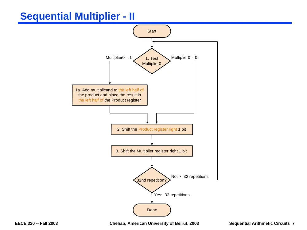
Sequential Multiplier - II
Done
1. Test
Multiplier0
1a. Add multiplicand to the left half of
the product and place the result in
the left half of the Product register
2. Shift the Product register right 1 bit
3. Shift the Multiplier register right 1 bit
32nd repetition?
Start
Multiplier0 = 0
Multiplier0 = 1
No: < 32 repetitions
Yes: 32 repetitions
EECE 320 -- Fall 2003
Chehab, American University of Beirut, 2003
Sequential Arithmetic Circuits 8
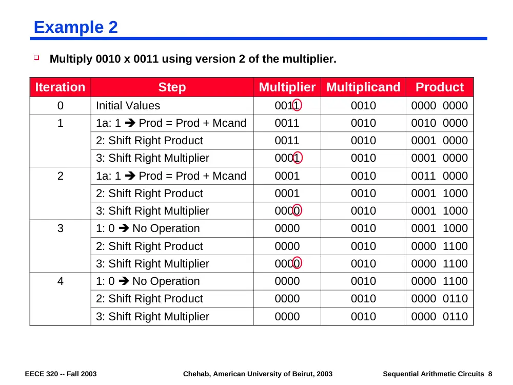
Example 2
Multiply 0010 x 0011 using version 2 of the multiplier.
Iteration
Step
Multiplier
Multiplicand
Product
0
Initial Values
0011
0010
0000 0000
1
1a: 1 Prod = Prod + Mcand
0011
0010
0010 0000
2: Shift Right Product
0011
0010
0001 0000
3: Shift Right Multiplier
0001
0010
0001 0000
2
1a: 1 Prod = Prod + Mcand
0001
0010
0011 0000
2: Shift Right Product
0001
0010
0001 1000
3: Shift Right Multiplier
0000
0010
0001 1000
3
1: 0 No Operation
0000
0010
0001 1000
2: Shift Right Product
0000
0010
0000 1100
3: Shift Right Multiplier
0000
0010
0000 1100
4
1: 0 No Operation
0000
0010
0000 1100
2: Shift Right Product
0000
0010
0000 0110
3: Shift Right Multiplier
0000
0010
0000 0110
EECE 320 -- Fall 2003
Chehab, American University of Beirut, 2003
Sequential Arithmetic Circuits 9
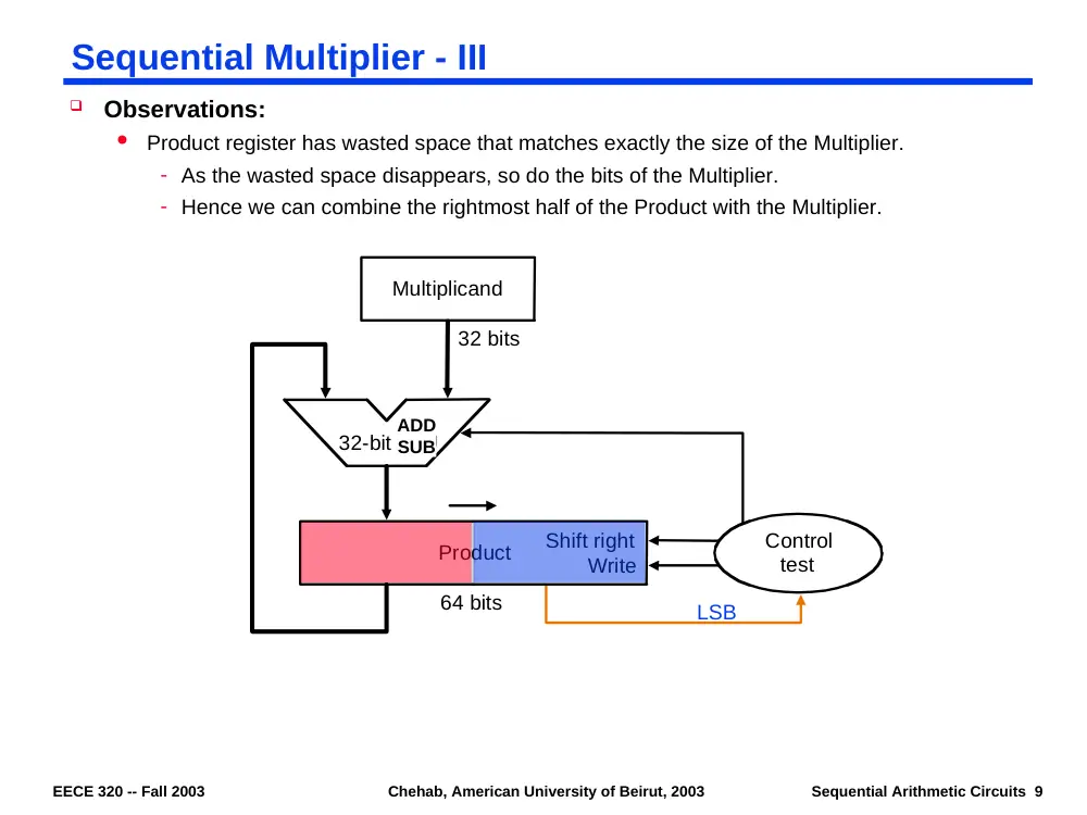
Sequential Multiplier - III
Observations:
Product register has wasted space that matches exactly the size of the Multiplier.
- As the wasted space disappears, so do the bits of the Multiplier.
- Hence we can combine the rightmost half of the Product with the Multiplier.
Control
test
Write
32 bits
64 bits
Shift right
Product
Multiplicand
32-bit ALU
LSB
ADD
SUB
EECE 320 -- Fall 2003
Chehab, American University of Beirut, 2003
Sequential Arithmetic Circuits 10
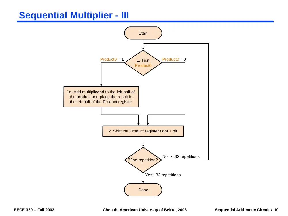
Sequential Multiplier - III
Done
1. Test
Product0
1a. Add multiplicand to the left half of
the product and place the result in
the left half of the Product register
2. Shift the Product register right 1 bit
32nd repetition?
Start
Product0 = 0
Product0 = 1
No: < 32 repetitions
Yes: 32 repetitions
EECE 320 -- Fall 2003
Chehab, American University of Beirut, 2003
Sequential Arithmetic Circuits 11
Example 3
Multiply 0010 x 0011 using version 3 of the multiplier.
Iteration
Step
Multiplicand
Product
0
Initial Values
0010
0000 0011
1
1a: 1 Prod = Prod + Mcand
0010
0010 0011
2: Shift Right Product
0010
0001 0001
2
1a: 1 Prod = Prod + Mcand
0010
0011 0001
2: Shift Right Product
0010
0001 1000
3
1: 0 No Operation
0010
0001 1000
2: Shift Right Product
0010
0000 1100
4
1: 0 No Operation
0010
0000 1100
2: Shift Right Product
0010
0000 0110
EECE 320 -- Fall 2003
Chehab, American University of Beirut, 2003
Sequential Arithmetic Circuits 12
What about Signed Multiplication?
Basic approach:
Store the signs of the operands
Convert signed numbers to unsigned numbers (most significant bit (MSB) = 0)
Perform multiplication
If sign bits of operands are equal then sign of product bit = 0, else sign bit is 1.
Improved method: Booth's Algorithm
Assumption: Adder and Subtractor are available
Another motivation is to reduce the number of partial products by
examining 2 or more bits of the multiplier.
Example: Multiply 2 x 6 = 0010 x 0110
We can get the same result in another way:
For example, since 6 = -2 + 8 (0110 = -00010 + 01000, 0110 = 11110 + 01000)
We can replace a string of 1s in the multiplier with an initial subtract when we first see a 1, and
then later add when we first see the bit after the last 1 in the string of 1s.
0 0 1 0ten
x 0 1 1 0ten
0 0 0 0
0 0 1 0
0 0 1 0
0 0 0 0
0 0 0 1 1 0 0ten
EECE 320 -- Fall 2003
Chehab, American University of Beirut, 2003
Sequential Arithmetic Circuits 13
Booth’s Algorithm
Algorithm: Scan the Multiplier from right to left and observe 2 bits at a time, the
current bit and the previous bit. Depending on their value, do one of the following:
00: Middle of a string of zeros, so no arithmetic operation.
01: End of a string of 1s, so add the Multiplicand to the left half of the Product.
10: Beginning of a string of 1s, so subtract Multiplicand from left half of the Product.
11: Middle of a string of 1s, so no arithmetic operation.
Then shift the Product register right 1 bit.
0 0 1 0ten
x 0 1 1 0ten
+ 0 0 0 0
- 0 0 1 0
+ 0 0 0 0
+ 0 0 1 0
0 0 0 1 1 0 0ten
EECE 320 -- Fall 2003
Chehab, American University of Beirut, 2003
Sequential Arithmetic Circuits 14
Comparison Between Original and Booth’s Algorithms
Assumptions:
Assume previous bit at startup to be 0.
When shifting the Product, do sign extension (arithmetic shift operation)
Arithmetic right shift: 1001010 --> 1100101
Logical right shift: 1001010 --> 0100101
Itera
tion
Multip
licand
Original Algorithm
Booth’s Algorithm
Step
Product
Step
Product
0
0010
Initial Values
0000 0110
Initial Values
0000 0110 0
1
0010
1:0 No Operation
0000 0110
1a: 00 No Operation
0000 0110 0
0010
2: Shift Right Product
0000 0011
2: Shift Right Product
0000 0011 0
2
0010
1a: 1 P = P + Mcand
0010 0011
1c: 10 P = P - Mcand
1110 0011 0
0010
2: Shift Right Product
0001 0001
2: Shift Right Product
1111 0001 1
3
0010
1a: 1 P = P + Mcand
0011 0001
1d: 11 No Operation
1111 0001 1
0010
2: Shift Right Product
0001 1000
2: Shift Right Product
1111 1000 1
4
0010
1:0 No Operation
0001 1000
1b: 01 P = P + Mcand
0001 1000 1
0010
2: Shift Right Product
0000 1100
2: Shift Right Product
0000 1100 0
EECE 320 -- Fall 2003
Chehab, American University of Beirut, 2003
Sequential Arithmetic Circuits 15
Another Example
Try Booth’s algorithm with negative numbers: Multiply 2 by -3 = -6, or
0010 x 1101 = 1111 1010.
Iteration
Step
Multiplicand
Product
0
Initial Values
0010
0000 1101 0
1
1c: 10 Prod = Prod - Mcand
0010
1110 1101 0
2: Shift Right Product
0010
1111 0110 1
2
1b: 01 Prod = Prod + Mcand
0010
0001 0110 1
2: Shift Right Product
0010
0000 1011 0
3
1c: 10 Prod = Prod - Mcand
0010
1110 1011 0
2: Shift Right Product
0010
1111 0101 1
4
1d: 11 No Operation
0010
1111 0101 1
2: Shift Right Product
0010
1111 1010 1
EECE 320 -- Fall 2003
Chehab, American University of Beirut, 2003
Sequential Arithmetic Circuits 16
Why Does Booth’s Alg. Work for 2s Complement Numbers
Let a=an-1an-2…a0 be the Multiplier, and b be the Multiplicand.
Booth’s algorithm says that if
(ai-1 - ai) = 0, do nothing
(ai-1 - ai) = 1, add b
(ai-1 - ai) = -1, subtract b
Shifting the Multiplicand left with respect to the Product is equivalent to
multiplying by a power of 2:
Sum can be simplified by noting that:
Recalling that a-1 = 0 and factoring out b, the sum reduces to:
EECE 320 -- Fall 2003
Chehab, American University of Beirut, 2003
Sequential Arithmetic Circuits 17
Modified Booth’s: Can we examine more than 2 bits at a time?
What if we examine 3 bits of the multiplier at a time?
Requires only 6 steps to complete as opposed to 12 in original algorithm.
Can list all possible 8 values of the 3 bits considered and the action taken:
Bits
Operation
000
NO Operation
001
Add Multiplicand
010
Add Multiplicand
011
Add 2xMultiplicand
100
Sub 2xMultiplicand
101
Sub Multiplicand
110
Sub Multiplicand
111
NO Operation
0 1 0 1 1 1 0 1 1 0 0 1 0
-Mcand+2Mcand = Mcand
0 1 0 1 1 1 0 1 1 0 0 1 0
-2Mcand
0 1 0 1 1 1 0 1 1 0 0 1 0
0+2Mcand = 2Mcand
0 1 0 1 1 1 0 1 1 0 0 1 0
-Mcand + 0
0 1 0 1 1 1 0 1 1 0 0 1 0
0+2Mcand = 2Mcand
0 1 0 1 1 1 0 1 1 0 0 1 0
-Mcand+2Mcand = Mcand
EECE 320 -- Fall 2003
Chehab, American University of Beirut, 2003
Sequential Arithmetic Circuits 18
Binary Division
Division is most complex of the four basic arithmetic operations.
Division of 2 operands, called Dividend (X) and Divisor (D), generates 2 results, Quotient
(Q) and Remainder (R) that satisfy:
where
1001010
1000
Quotient
Divisor
1
1000
-
0010
0
0101
0
1010
1000
-
0010
Dividend
Remainder
1
Example:
EECE 320 -- Fall 2003
Chehab, American University of Beirut, 2003
Sequential Arithmetic Circuits 19
Binary Division
Basic division algorithm tries to see how big a number can be subtracted from
Dividend, creating a bit of the quotient at each step.
For binary, it is easy to find out how many times the Divisor goes into the portion of the
Dividend.
It is either 0 x Divisor, or 1 x Divisor.
In typical arithmetic units, where operands are represented using n-bits (single-length
registers), a double length product (2n bits) is available after a multiply operation.
We wish to allow the use of this result in a subsequent Divide operation.
Hence Dividend (X) is represented using 2n bits, while D,Q, and R are represented using n bits.
To make sure that Q fits in n bits (i.e., Q<2n assuming unsigned numbers),
We must have X < 2n D, otherwise, we have an overflow condition.
EX: if Divisor=1, get an overflow if X >= 2n.
Also need to check that Divisor 0
Generate a Divide-by-zero signal when D=0.
First we assume all numbers are unsigned, and perform division.
Later generalize for signed numbers:
sign(Quotient) = -1 iff sign(Dividend) sign(Divisor)
sign(Remainder) = sign(Dividend)
EECE 320 -- Fall 2003
Chehab, American University of Beirut, 2003
Sequential Arithmetic Circuits 20
Divider - I
Assume Dividend is a 64-bit number and Divisor a 32-bit number (such that X < 232 D).
Registers used to store operands and results:
64-bit Divisor register with Divisor stored in left half (to allow for aligning divisor with Dividend),
32-bit Quotient register
64-bit Remainder register initialized with the Dividend
Divider uses a 64-bit adder/subtractor to perform division.
64-bit ALU
Control
test
Quotient
Shift left
Remainder
Write
Divisor
Shift right
64 bits
64 bits
32 bits
ADD/SUB
64-bit
EECE 320 -- Fall 2003
Chehab, American University of Beirut, 2003
Sequential Arithmetic Circuits 21
Divider - I
For n-bit Quotient and
Remainder, algorithm
requires n+1 steps to
complete.
First step of algorithm
cannot generate a
Quotient bit of 1 because
the condition X < 232 D
must be satisfied.
Note that placing the
divisor in the left half of the
64-bit Divisor register is
equivalent to multiplying D
by 232.
Since Remainder register
is initialized with X
(Dividend), then the first
time we compare R to
Divisor register we get
leave
restore
Hence result of first step
is useless.
Done
Test Remainder
2a. Shift the Quotient register to the left,
setting the new rightmost bit to 1
3. Shift the Divisor register right 1 bit
33rd repetition?
Start
Remainder < 0
No: < 33 repetitions
Yes: 33 repetitions
2b. Restore the original value by adding
the Divisor register to the Remainder
register and place the sum in the
Remainder register. Also shift the
Quotient register to the left, setting the
new least significant bit to 0
1. Subtract the Divisor register from the
Remainder register and place the
result in the Remainder register
Remainder 0
EECE 320 -- Fall 2003
Chehab, American University of Beirut, 2003
Sequential Arithmetic Circuits 22
Example - Divider 1
Divide 7 by 2: 0000 0111 : 0010
Shift left logical
EECE 320 -- Fall 2003
Chehab, American University of Beirut, 2003
Sequential Arithmetic Circuits 23
Divider - II
Since at most half of Divisor register has useful info, both Divisor and
Adder/Subtractor sizes can be cut in half.
Shifting the Remainder to the left instead of shifting Divisor to the right achieves the
required alignment and simplifies the hardware.
Remainder is still initialized with Dividend.
The useless first step of the previous algorithm can be eliminated by switching the
order of the operations to shift the Remainder register left first and then subtract
Divisor from left half of the Remainder register.
When the algorithm terminates, the remainder will be in the left half of the Remainder
register.
Control
test
Quotient
Shift left
Write
32 bits
64 bits
32 bits
Shift left
Divisor
32-bit ALU
Remainder
ADD
SUB
EECE 320 -- Fall 2003
Chehab, American University of Beirut, 2003
Sequential Arithmetic Circuits 24
Divider - III
Similar to the third version of the multiplication algorithm, the Quotient register can
be eliminated by shifting the bits of the quotient into the Remainder register instead
of shifting 0s as in preceding algorithm.
Start by shifting the Remainder left as before
Therefore the loop contains only 2 steps because the shifting of the Remainder register shifts both
the remainder in the left half and quotient in the right half.
The consequence of combining the 2 registers together and the new order of the operations in the
loop is that the remainder will be shifted left one time too many to make room for the last quotient
bit on the right.
Thus the final correction step must shift back only the remainder in the left half of the register.
ADD/SUB
32-bit
EECE 320 -- Fall 2003
Chehab, American University of Beirut, 2003
Sequential Arithmetic Circuits 25
Divider - III
Requires same hardware
as shift-and-add multiplier.
Done. Shift left half of Remainder right 1 bit
Test Remainder
3a. Shift the Remainder register to the
left, setting the new rightmost bit to 1
32nd repetition?
Start
Remainder < 0
No: < 32 repetitions
Yes: 32 repetitions
3b. Restore the original value by adding
the Divisor register to the left half of the
Remainder register and place the sum
in the left half of the Remainder register.
Also shift the Remainder register to the
left, setting the new rightmost bit to 0
2. Subtract the Divisor register from the
left half of the Remainder register and
place the result in the left half of the
Remainder register
Remainder 0
1. Shift the Remainder register left 1 bit
EECE 320 -- Fall 2003
Chehab, American University of Beirut, 2003
Sequential Arithmetic Circuits 26
Example
Divide 7 by 2: 0000 0111 by 0010
Iteration
Step
Divisor
Remainder
0
Initial Values
0010
0000 0111
Shift Rem Left 1
0010
0000 1110
1
2: Rem = Rem - Div
0010
1110 1110
3b: Rem < 0 +Div, SLL R, R0 = 0
0010
0001 1100
2
2: Rem = Rem – Div
0010
1111 1100
3b: Rem < 0 +Div, SLL R, R0 = 0
0010
0011 1000
3
2: Rem = Rem – Div
0010
0001 1000
3a: Rem ≥ 0 SLL R, R0 = 1
0010
0011 0001
4
2: Rem = Rem - Div
0010
0001 0001
3a: Rem ≥ 0 SLL R, R0 = 1
0010
0010 0011
Shift Left Half of Rem Right 1
0010
0001 0011
EECE 320 -- Fall 2003
Chehab, American University of Beirut, 2003
Sequential Arithmetic Circuits 27
Signed Division
Simplest way is to remember signs, make operands positive, divide, and at the end
complementation of Quotient and Remainder may be necessary.
Set sign of Quotient to -1 if Sign(Dividend) Sign(Divisor)
Sign(Remainder) = Sign(Dividend)
Example: +7 ÷ -2: Quotient = -3, Remainder = +1
-7 ÷ -2: Quotient = +3, Remainder = -1