
EECE 320 Lecture 5, Fall 2011
American University of Beirut · Digital Systems Design · 9 pages · Prof. Ali Chehab
More EECE 320 files
Show the text of this lab
EECE 320 L5: Combinational Logic design Principles 1
Chehab, AUB, 2003
EECE 320
Digital Systems Design
Lecture 5:
Combinational Logic Design
Principles
Ali Chehab
EECE 320 L5: Combinational Logic design Principles 2
Chehab, AUB, 2003
Combinational Circuit Analysis
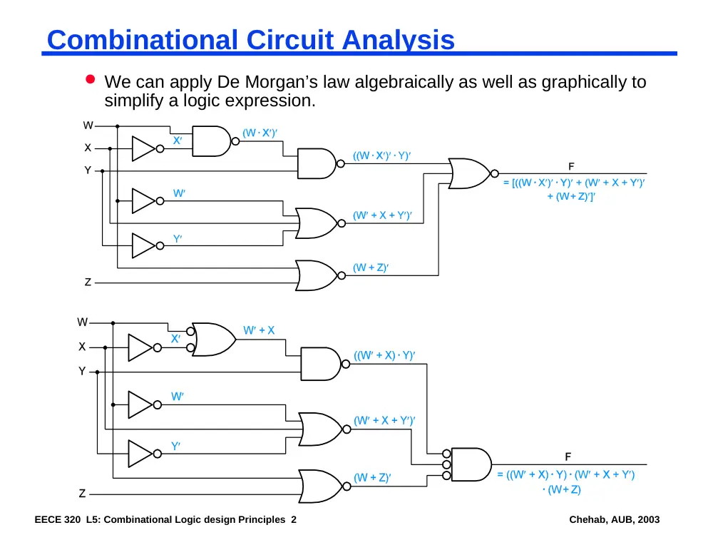
We can apply De Morgan’s law algebraically as well as graphically to
simplify a logic expression.
EECE 320 L5: Combinational Logic design Principles 3
Chehab, AUB, 2003
Combinational Circuit Analysis
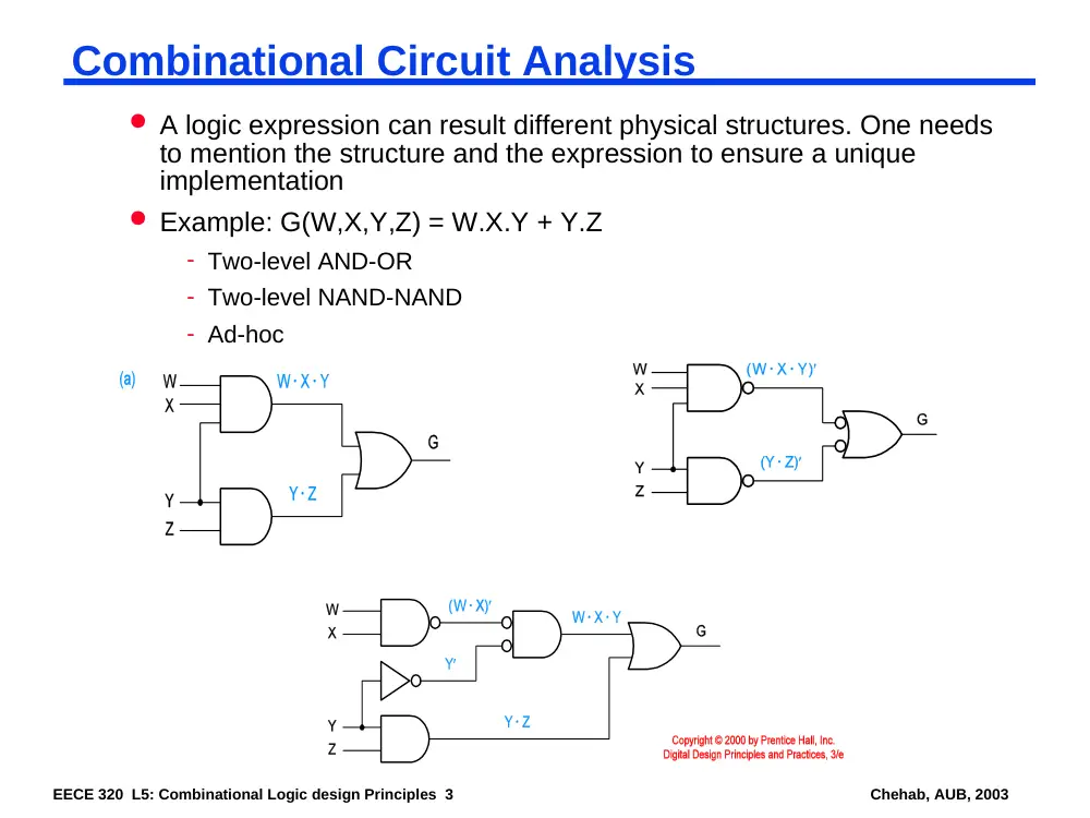
A logic expression can result different physical structures. One needs
to mention the structure and the expression to ensure a unique
implementation
Example: G(W,X,Y,Z) = W.X.Y + Y.Z
- Two-level AND-OR
- Two-level NAND-NAND
- Ad-hoc
EECE 320 L5: Combinational Logic design Principles 4
Chehab, AUB, 2003
Combinational Circuit Synthesis
A logic function is usually described verbally, by a list of combinations that
make it ON or OFF, or using or notation.
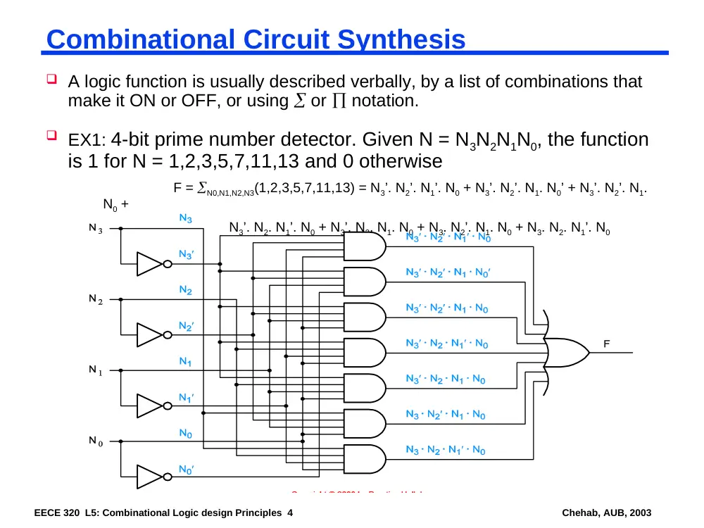
EX1: 4-bit prime number detector. Given N = N3N2N1N0, the function
is 1 for N = 1,2,3,5,7,11,13 and 0 otherwise
F = N0,N1,N2,N3(1,2,3,5,7,11,13) = N3’. N2’. N1’. N0 + N3’. N2’. N1. N0’ + N3’. N2’. N1.
N0 +
N3’. N2. N1’. N0 + N3’. N2. N1. N0 + N3. N2’. N1. N0 + N3. N2. N1’. N0
EECE 320 L5: Combinational Logic design Principles 5
Chehab, AUB, 2003
Combinational Circuit Synthesis
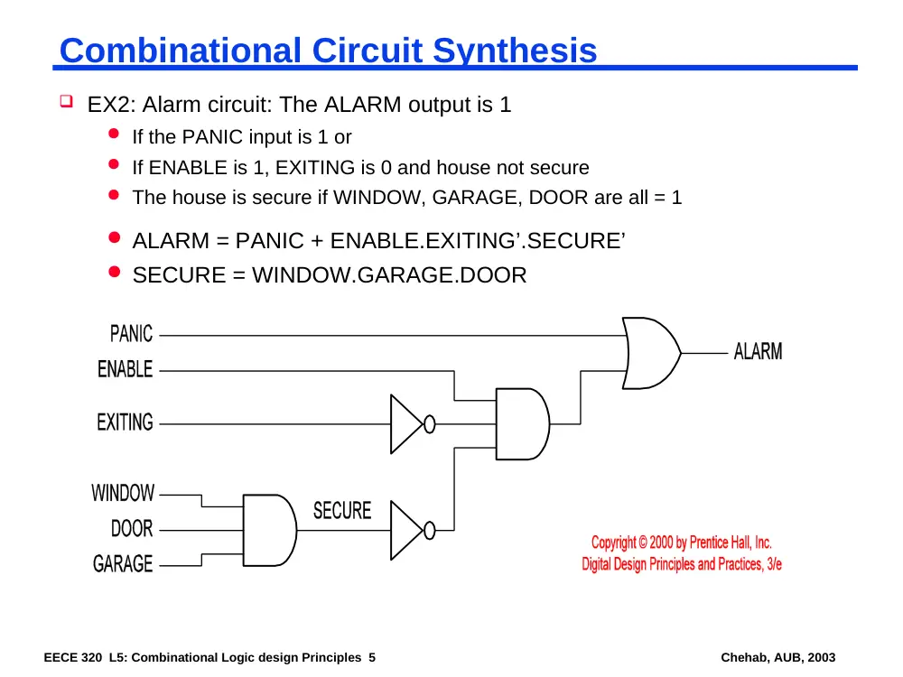
EX2: Alarm circuit: The ALARM output is 1
If the PANIC input is 1 or
If ENABLE is 1, EXITING is 0 and house not secure
The house is secure if WINDOW, GARAGE, DOOR are all = 1
ALARM = PANIC + ENABLE.EXITING’.SECURE’
SECURE = WINDOW.GARAGE.DOOR
EECE 320 L5: Combinational Logic design Principles 6
Chehab, AUB, 2003
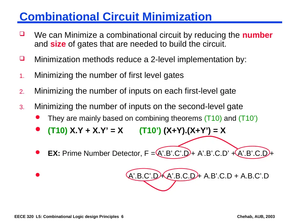
Combinational Circuit Minimization
We can Minimize a combinational circuit by reducing the number
and size of gates that are needed to build the circuit.
Minimization methods reduce a 2-level implementation by:
1.
Minimizing the number of first level gates
2.
Minimizing the number of inputs on each first-level gate
3.
Minimizing the number of inputs on the second-level gate
They are mainly based on combining theorems (T10) and (T10’)
(T10) X.Y + X.Y’ = X
(T10’) (X+Y).(X+Y’) = X
EX: Prime Number Detector, F = A’.B’.C’.D + A’.B’.C.D’ + A’.B’.C.D +
A’.B.C’.D + A’.B.C.D + A.B’.C.D + A.B.C’.D
EECE 320 L5: Combinational Logic design Principles 7
Chehab, AUB, 2003
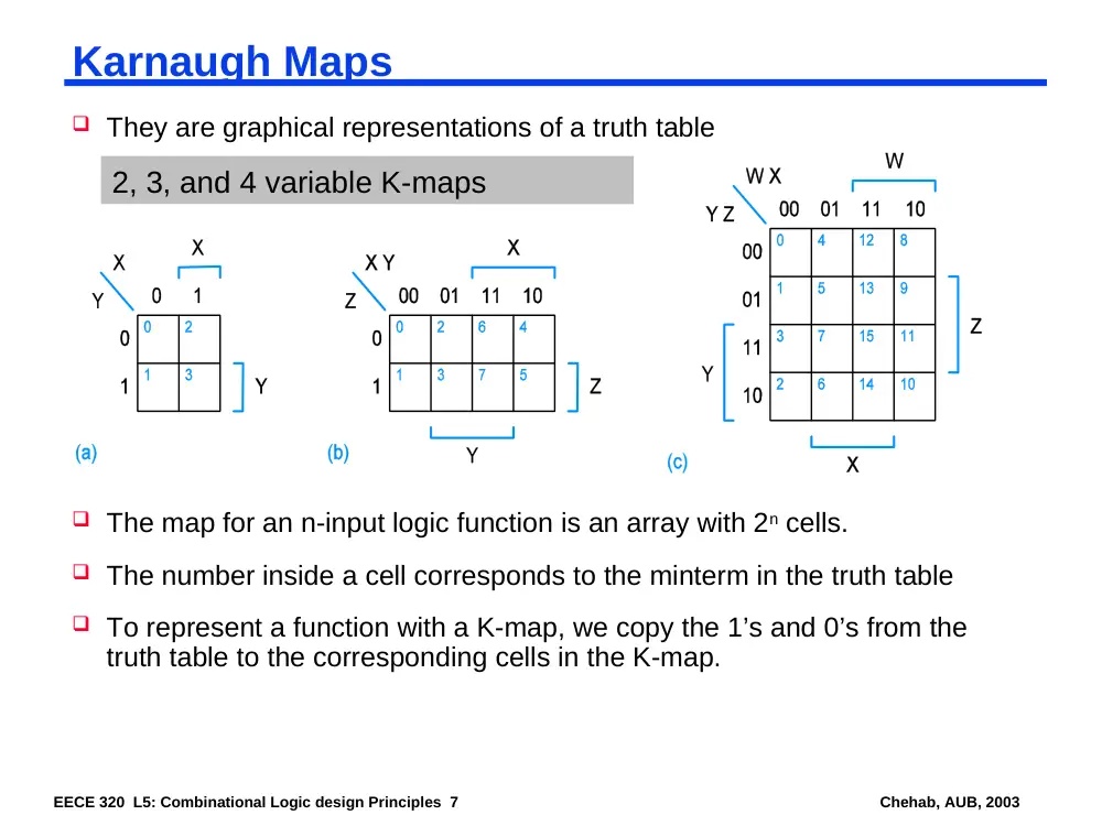
Karnaugh Maps
They are graphical representations of a truth table
2, 3, and 4 variable K-maps
The map for an n-input logic function is an array with 2n cells.
The number inside a cell corresponds to the minterm in the truth table
To represent a function with a K-map, we copy the 1’s and 0’s from the
truth table to the corresponding cells in the K-map.
EECE 320 L5: Combinational Logic design Principles 8
Chehab, AUB, 2003
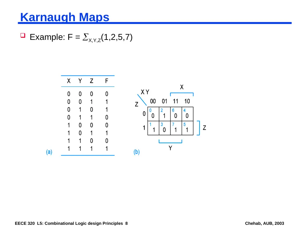
Karnaugh Maps
Example: F = X,Y,Z(1,2,5,7)
EECE 320 L5: Combinational Logic design Principles 9
Chehab, AUB, 2003
Next Lecture and Reminders
Next lecture
Reminders