
EECE 380 Problems Solution Manual, Fall 2011
American University of Beirut · Engineering Electromagnetics · 33 pages · with solution


Showing the first 10 of 33 pages. Download the PDF to see all of it.
More EECE 380 files
- Problems Solution Manual · Fall 2011Problems · with solutionView
- Problems Solution Manual · Fall 2011Problems · with solutionView
- Problems Solution Manual · Fall 2011Problems · with solutionView
- Problems Solution Manual · Fall 2011Problems · with solutionView
- Problems Solution Manual · Fall 2011Problems · with solutionView
- Problems Solution Manual · Fall 2011Problems · with solutionView
- Problems Solution Manual · Fall 2011Problems · with solutionView
- Problems · Spring 2008ProblemsView
Show the text of this problems
317
Chapter 7: Plane-Wave Propagation
Lesson #43
Chapter — Section: 7-1
Topics: Time-harmonic fields
Highlights:
• Phasors
• Complex permittivity
• Wave equations
Special Illustrations:
318
Lesson #44
Chapter — Section: 7-2
Topics: Waves in lossless media
Highlights:
• Uniform plane waves
• Intrinsic impedance
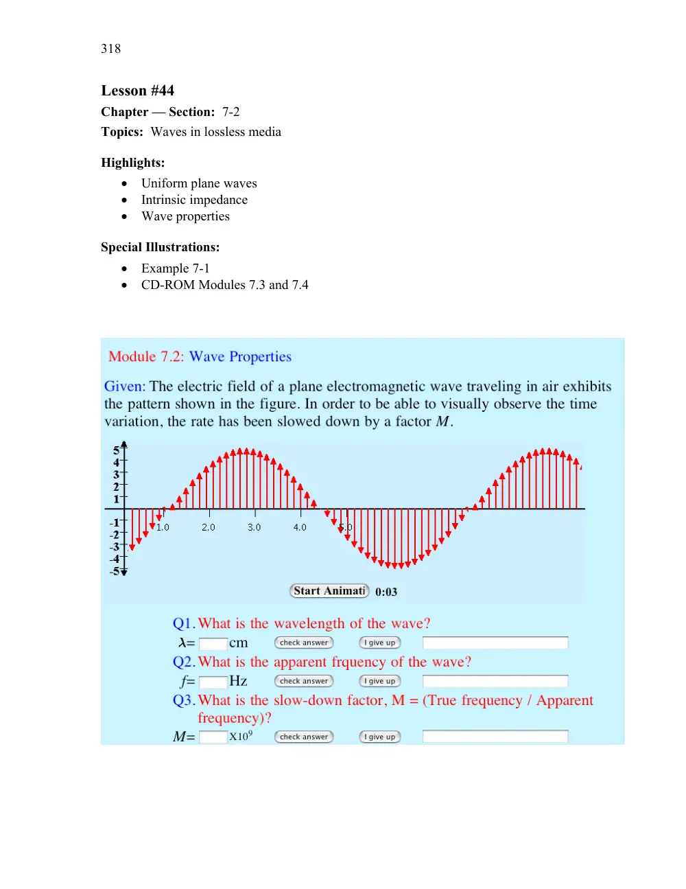
• Wave properties
Special Illustrations:
• Example 7-1
• CD-ROM Modules 7.3 and 7.4
319
Lesson #45 and 46
Chapter — Section: 7-3
Topics: Wave polarization
Highlights:
• Definition of polarization
• Linear, circular, elliptical
Special Illustrations:
• CD-ROM Demos 7.1-7.5
• Liquid Crystal Display
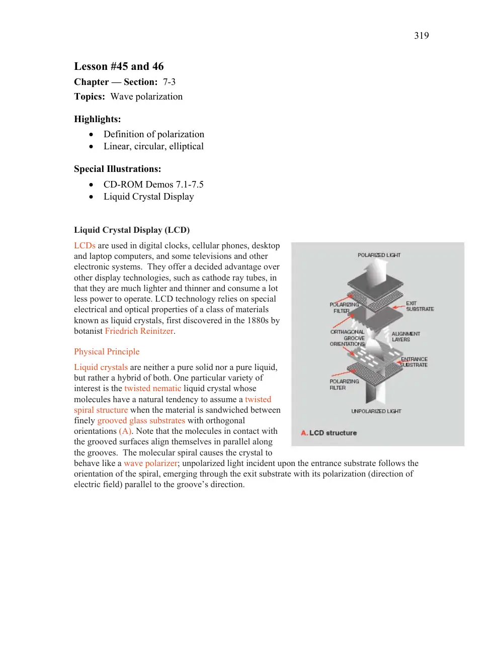
Liquid Crystal Display (LCD)
LCDs are used in digital clocks, cellular phones, desktop
and laptop computers, and some televisions and other
electronic systems. They offer a decided advantage over
other display technologies, such as cathode ray tubes, in
that they are much lighter and thinner and consume a lot
less power to operate. LCD technology relies on special
electrical and optical properties of a class of materials
known as liquid crystals, first discovered in the 1880s by
botanist Friedrich Reinitzer.
Physical Principle
Liquid crystals are neither a pure solid nor a pure liquid,
but rather a hybrid of both. One particular variety of
interest is the twisted nematic liquid crystal whose
molecules have a natural tendency to assume a twisted
spiral structure when the material is sandwiched between
finely grooved glass substrates with orthogonal
orientations (A). Note that the molecules in contact with
the grooved surfaces align themselves in parallel along
the grooves. The molecular spiral causes the crystal to
behave like a wave polarizer; unpolarized light incident upon the entrance substrate follows the
orientation of the spiral, emerging through the exit substrate with its polarization (direction of
electric field) parallel to the groove’s direction.
320
Lesson #47
Chapter — Section: 7-4
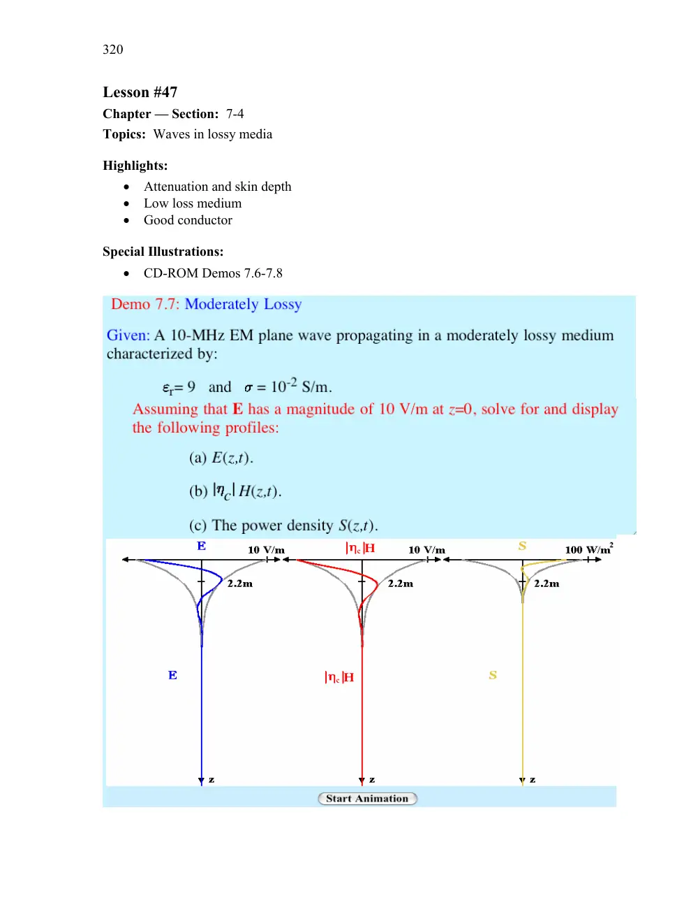
Topics: Waves in lossy media
Highlights:
• Attenuation and skin depth
• Low loss medium
• Good conductor
Special Illustrations:
• CD-ROM Demos 7.6-7.8
321
Lesson #48
Chapter — Section: 7-5
Topics: Current flow in conductors
Highlights:
• Skin depth dependence on frequency
• Surface impedance
Special Illustrations:
322
Lesson #49
Chapter — Section: 7-6
Topics: EM power density
Highlights:
• Power density in a lossless medium
• Power density in a lossy medium
• Time-average power
Special Illustrations:
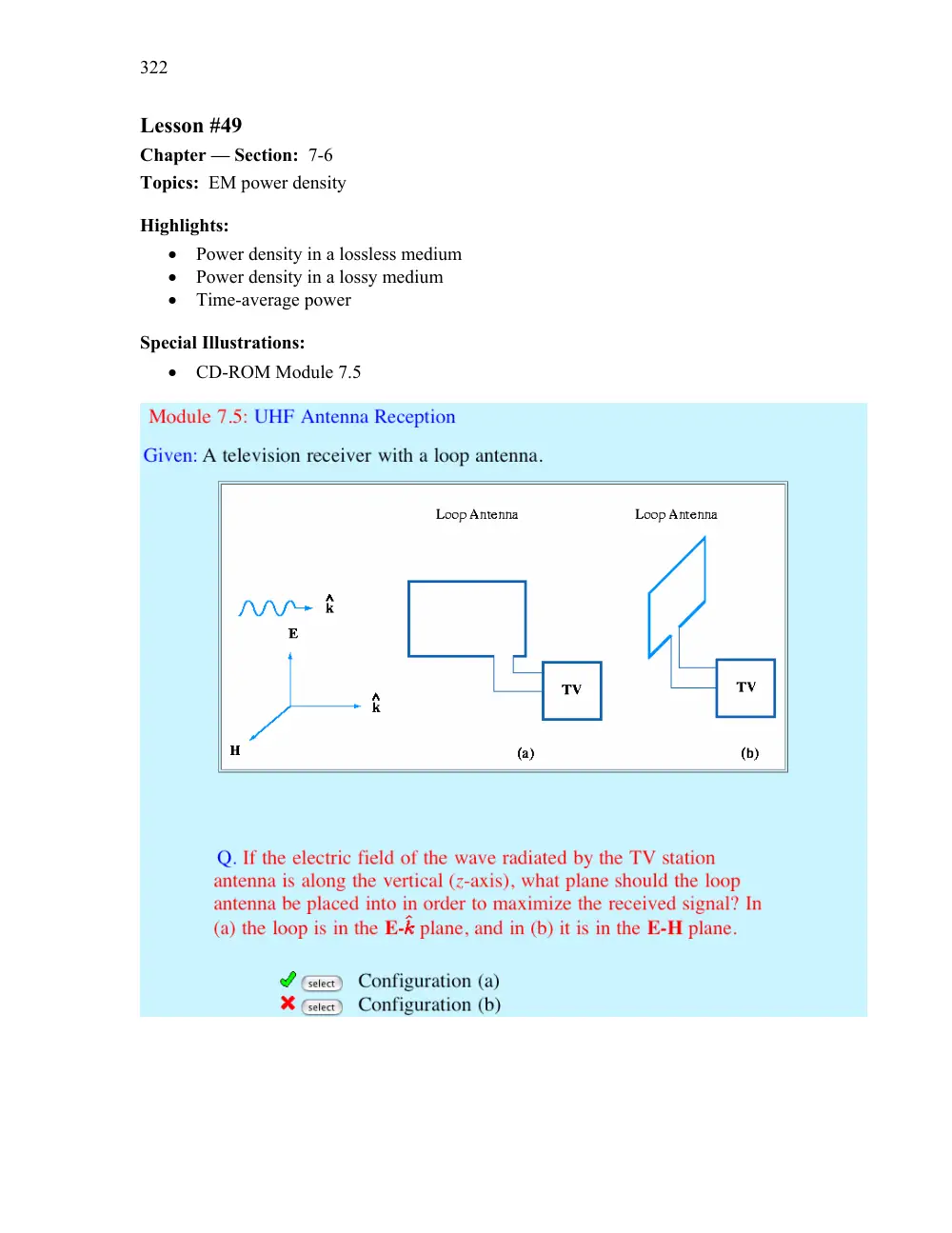
• CD-ROM Module 7.5
CHAPTER 7
323
Chapter 7
Section 7-2: Propagation in Lossless Media
Problem 7.1
The magnetic field of a wave propagating through a certain
nonmagnetic material is given by
H
�
ˆz30cos
� 108t
�
0
5y
�
(mA/m)
Find (a) the direction of wave propagation, (b) the phase velocity, (c) the wavelength
in the material, (d) the relative permittivity of the material, and (e) the electric field
phasor.
Solution:
(a) Positive y-direction.
(b) ω
�
108 rad/s, k
�
0
5 rad/m.
up
�
ω
k
�
108
0
5
�
2
108 m/s
(c) λ
�
2π
k
�
2π
0
5
�
12
6 m.
(d) εr
�
�
c
up
2
�
� 3
108
2
108
2
�
2
25.
(e) From Eq. (7.39b),
�
E
�
� ηˆk
�
H
�
η
�
�
µ
ε
�
120π
� εr
�
120π
1
5
�
251
33
(Ω)
�
ˆk
�
ˆy
�
and
�
H
�
ˆz30e
j0
� 5y
10
3
(A/m)
Hence,
�
E
�
� 251
33ˆy
ˆz30e
j0
� 5y
10
3
�
� ˆx7
54e
j0
� 5y
(V/m)
�
and
E
� y
� t
��
��
�
�
Eejωt
��
� ˆx7
54cos
� 108t
�
0
5y
�
(V/m)
Problem 7.2
Write general expressions for the electric and magnetic fields of a
1-GHz sinusoidal plane wave traveling in the
� y-direction in a lossless nonmagnetic
medium with relative permittivity εr
�
9. The electric field is polarized along the
x-direction, its peak value is 6 V/m and its intensity is 4 V/m at t
�
0 and y
�
2 cm.
324
CHAPTER 7
Solution: For f
�
1 GHz, µr
�
1, and εr
�
9,
ω
�
2π f
�
2π
109 rad/s
�
k
�
2π
λ
�
2π
λ0
� εr
�
2π f
c
� εr
�
2π
109
3
108
� 9
�
20π rad/m
�
E
� y
� t
��
ˆx6cos
� 2π
109t
�
20πy
�
φ0
�
(V/m)
At t
�
0 and y
�
2 cm, E
�
4 V/m:
4
�
6cos
�
� 20π
2
10
2
�
φ0
��
6cos
�
� 0
4π
�
φ0
�
Hence,
φ0
�
0
4π
�
cos
1
� 4
6
�
0
84 rad
�
which gives
φ0
�
2
1 rad
�
120
19
�
and
E
� y
� t
��
ˆx6cos
� 2π
109t
�
20πy
�
120
19
�
�
(V/m)
Problem 7.3
The electric field phasor of a uniform plane wave is given by
�
E
�
ˆy10ej0
� 2z (V/m). If the phase velocity of the wave is 1
5
108 m/s and the relative
permeability of the medium is µr
�
2
4, find (a) the wavelength, (b) the frequency f
of the wave, (c) the relative permittivity of the medium, and (d) the magnetic field
H
� z
� t
� .
Solution:
(a) From
�
E
�
ˆy10ej0
� 2z (V/m), we deduce that k
�
0
2 rad/m. Hence,
λ
�
2π
k
�
2π
0
2
�
10π
�
31
42 m
(b)
f
�
up
λ
�
1
5
108
31
42
�
4
77
106 Hz
�
4
77 MHz
(c) From
up
�
c
� µrεr
�
εr
�
1
µr
�
c
up
2
�
1
2
4
�
3
1
5
2
�
1
67
CHAPTER 7
325
(d)
η
�
�
µ
ε
�
120π
�
µr
εr
�
120π
�
2
4
1
67
�
451
94
(Ω)
�
�
H
�
1
η
�
� ˆz
��
�
E
�
1
η
�
� ˆz
��
ˆy10ej0
� 2z
�
ˆx22
13e j0
� 2z
(mA/m)
�
H
� z
� t
��
ˆx22
13cos
� ωt
�
0
2z
�
(mA/m)
�
with ω
�
2π f
�
9
54π
106 rad/s.
Problem 7.4
The electric field of a plane wave propagating in a nonmagnetic
material is given by
E
�
� ˆy3sin
� π
107t
�
0
2πx
�
�
ˆz4cos
� π
107t
�
0
2πx
��
(V/m)
Determine (a) the wavelength, (b) εr, and (c) H.
Solution:
(a) Since k
�
0
2π,
λ
�
2π
k
�
2π
0
2π
�
10 m
(b)
up
�
ω
k
�
π
107
0
2π
�
5
107 m/s
But
up
�
c
� εr
Hence,
εr
�
�
c
up
2
�
� 3
108
5
107
2
�
36
(c)
H
�
1
η
ˆk
E
�
1
η ˆx
�
ˆy3sin
� π
107t
�
0
2πx
�
�
ˆz4cos
� π
107t
�
0
2πx
�
�
�
ˆz 3
η sin
� π
107t
�
0
2πx
�
�
ˆy 4
η cos
� π
107t
�
0
2πx
�
(A/m)
�
326
CHAPTER 7
with
η
�
η0
� εr
�
120π
6
�
20π
�
62
83
(Ω)
Problem 7.5
A wave radiated by a source in air is incident upon a soil surface,
whereupon a part of the wave is transmitted into the soil medium. If the wavelength
of the wave is 60 cm in air and 20 cm in the soil medium, what is the soil’s relative
permittivity? Assume the soil to be a very low loss medium.
Solution: From λ
�
λ0
� εr,
εr
�
� λ0
λ
2
�
� 60
20
2
�
9
Problem 7.6
The electric field of a plane wave propagating in a lossless,
nonmagnetic, dielectric material with εr
�
2
56 is given by
E
�
ˆy20cos
� 6π
109t
�
kz
�
(V/m)
Determine:
(a) f, up, λ, k, and η, and
(b) the magnetic field H.
Solution:
(a)
ω
�
2π f
�
6π
109 rad/s
�
f
�
3
109 Hz
�
3 GHz
�
up
�
c
� εr
�
3
108
� 2
56
�
1
875
108 m/s
�
λ
�
up
f
�
1
875
108
6
109
�
3
12 cm
�
k
�
2π
λ
�
2π
3
12
10
2
�
201
4 rad/m
�
η
�
η0
� εr
�
377
� 2
56
�
377
1
6
�
235
62 Ω
CHAPTER 7
327
(b)
H
�
� ˆx 20
η cos
� 6π
109t
�
kz
�
�
� ˆx
20
235
62 cos
� 6π
109t
�
201
4z
�
�
� ˆx8
49
10
2 cos
� 6π
109t
�
201
4z
�
(A/m)
Section 7-3: Wave Polarization
Problem 7.7
An RHC-polarized wave with a modulus of 2 (V/m) is traveling in free
space in the negative z-direction. Write down the expression for the wave’s electric
field vector, given that the wavelength is 6 cm.
y
x
z
ωt=0
ωt=π/2
Figure P7.7: Locus of E versus time.
Solution: For an RHC wave traveling in
� ˆz, let us try the following:
E
�
ˆxacos
� ωt
�
kz
�
�
ˆyasin
� ωt
�
kz
�
Modulus
� E
�
�
� a2
�
a2
�
a
� 2
�
2 (V/m). Hence,
a
�
2
� 2
�
� 2
328
CHAPTER 7
Next, we need to check the sign of the ˆy-component relative to that of the
ˆx-component. We do this by examining the locus of E versus t at z
�
0: Since
the wave is traveling along
� ˆz, when the thumb of the right hand is along
�
ˆz (into
the page), the other four fingers point in the direction shown (clockwise as seen from
above). Hence, we should reverse the sign of the ˆy-component:
E
�
ˆx
� 2cos
� ωt
�
kz
�
�
ˆy
� 2sin
� ωt
�
kz
�
(V/m)
with
k
�
2π
λ
�
2π
6
10
2
�
104
72
(rad/m)
�
and
ω
�
kc
�
2π
λ
3
108
�
π
1010
(rad/s)
Problem 7.8
For a wave characterized by the electric field
E
� z
� t
��
ˆxax cos
� ωt
�
kz
�
�
ˆyay cos
� ωt
�
kz
�
δ
�
�
identify the polarization state, determine the polarization angles
� γ
� χ
� , and sketch the
locus of E
� 0
� t
� for each of the following cases:
(a) ax
�
3 V/m, ay
�
4 V/m, and δ
�
0,
(b) ax
�
3 V/m, ay
�
4 V/m, and δ
�
180
� ,
(c) ax
�
3 V/m, ay
�
3 V/m, and δ
�
45
� ,
(d) ax
�
3 V/m, ay
�
4 V/m, and δ
�
� 135
� .
Solution:
ψ0
�
tan
1
� ay
ax
�
�
[Eq. (7.60)]
�
tan2γ
�
� tan2ψ0
� cosδ
[Eq. (7.59a)]
�
sin2χ
�
� sin2ψ0
� sinδ
[Eq. (7.59b)]
Case
ax
ay
δ
ψ0
γ
χ
Polarization State
(a)
3
4
0
53
13
�
53
13
�
0
Linear
(b)
3
4
180
�
53
13
�
� 53
13
�
0
Linear
(c)
3
3
45
�
45
�
45
�
22
5
�
Left elliptical
(d)
3
4
� 135
�
53
13
�
� 56
2
�
� 21
37
�
Right elliptical
(a) E
� z
� t
��
ˆx3cos
� ωt
�
kz
�
�
ˆy4cos
� ωt
�
kz
� .
(b) E
� z
� t
��
ˆx3cos
� ωt
�
kz
�
�
ˆy4cos
� ωt
�
kz
� .
(c) E
� z
� t
��
ˆx3cos
� ωt
�
kz
�
�
ˆy3cos
� ωt
�
kz
�
45
�
� .
(d) E
� z
� t
��
ˆx3cos
� ωt
�
kz
�
�
ˆy4cos
� ωt
�
kz
�
135
�
� .
CHAPTER 7
329
-3
-2
-1
1
2
3
-4
4
-4
-2
4
2
-4
4
-3
-2
-1
1
2
3
-4
-2
2
4
-4
4
-3
-2
-1
1
2
3
-4 -3
-2 -1
2
1
3
4
-3
-2
-1
1
2
3
-4
4
-4
-2
4
2
-3
-1
1
3
(a)
(b)
(c)
(d)
y
x
y
x
y
x
y
x
Figure P7.8: Plots of the locus of E
� 0
� t
� .
Problem 7.9
The electric field of a uniform plane wave propagating in free space
is given by
�
E
�
� ˆx
�
jˆy
� 20e
jπz
� 6 (V/m). Specify the modulus and direction of the
electric field intensity at the z
�
0 plane at t
�
0, 5 and 10 ns.
330
CHAPTER 7
Solution:
E
� z
� t
��
��
�
�
Eejωt
�
�
��
�
� ˆx
�
jˆy
� 20e
jπz
� 6ejωt
�
�
��
�
� ˆx
�
ˆyejπ
� 2
� 20e
jπz
� 6ejωt
�
�
ˆx20cos
� ωt
�
πz
6
�
�
ˆy20cos
� ωt
�
πz
6
�
π
2
�
�
ˆx20cos
� ωt
�
πz
6
�
�
ˆy20sin
� ωt
�
πz
6
�
(V/m)
�
� E
�
�
�
E2
x
�
E2
y
�
1
� 2
�
20
(V/m)
�
ψ
�
tan
1
� Ey
Ex
�
�
� ωt
�
πz
6
�
From
f
�
c
λ
�
kc
2π
�
π
6
3
108
2π
�
2
5
107 Hz
�
ω
�
2π f
�
5π
107 rad/s
At z
�
0,
ψ
�
� ωt
�
� 5π
107t
��
�� 0
at t
�
0
�
� 0
25π
�
� 45
�
at t
�
5ns
�
� 0
5π
�
� 90
�
at t
�
10ns
Therefore, the wave is LHC polarized.
Problem 7.10
A linearly polarized plane wave of the form
�
E
�
ˆxaxe
jkz can be
expressed as the sum of an RHC polarized wave with magnitude aR and an LHC
polarized wave with magnitude aL. Prove this statement by finding expressions for
aR and aL in terms of ax.
Solution:
�
E
�
ˆxaxe
jkz
�
RHC wave:
�
ER
�
aR
� ˆx
�
ˆye
jπ
� 2
� e
jkz
�
aR
� ˆx
�
jˆy
� e
jkz
�
LHC wave:
�
EL
�
aL
� ˆx
�
ˆyejπ
� 2
� e
jkz
�
aL
� ˆx
�
jˆy
� e
jkz
�
�
E
�
�
ER
�
�
EL
�
ˆxax
�
aR
� ˆx
�
jˆy
�
�
aL
� ˆx
�
jˆy
�
By equating real and imaginary parts, ax
�
aR
�
aL, 0
�
� aR
�
aL, or aL
�
ax
2,
aR
�
ax
2.
CHAPTER 7
331
Problem 7.11
The electric field of an elliptically polarized plane wave is given by
E
� z
� t
��
�
� ˆx10sin
� ωt
�
kz
�
60
�
�
�
ˆy30cos
� ωt
�
kz
��
(V/m)
Determine (a) the polarization angles
� γ
� χ
� and (b) the direction of rotation.
Solution:
(a)
E
� z
� t
��
�
�
ˆx10sin
� ωt
�
kz
�
60
�
�
�
ˆy30cos
� ωt
�
kz
��
�
� ˆx10cos
� ωt
�
kz
�
30
�
�
�
ˆy30cos
� ωt
�
kz
��
(V/m)
Phasor form:
�
E
�
� ˆx10ej30
�
�
ˆy30
� e
jkz
Since δ is defined as the phase of Ey relative to that of Ex,
δ
�
� 30
�
�
ψ0
�
tan
1
� 30
10
�
71
56
�
�
tan2γ
�
� tan2ψ0
� cosδ
�
� 0
65
or γ
�
73
5
�
�
sin2χ
�
� sin2ψ0
� sinδ
�
� 0
40
or χ
�
� 8
73
�
(b) Since χ
�
0, the wave is right-hand elliptically polarized.
Problem 7.12
Compare the polarization states of each of the following pairs of
plane waves:
(a) wave 1: E1
�
ˆx2cos
� ωt
�
kz
�
�
ˆy2sin
� ωt
�
kz
� ,
wave 2: E2
�
ˆx2cos
� ωt
�
kz
�
�
ˆy2sin
� ωt
�
kz
� ,
(b) wave 1: E1
�
ˆx2cos
� ωt
�
kz
�
�
ˆy2sin
� ωt
�
kz
� ,
wave 2: E2
�
ˆx2cos
� ωt
�
kz
�
�
ˆy2sin
� ωt
�
kz
� .
Solution:
(a)
E1
�
ˆx2cos
� ωt
�
kz
�
�
ˆy2sin
� ωt
�
kz
�
�
ˆx2cos
� ωt
�
kz
�
�
ˆy2cos
� ωt
�
kz
�
π
2
�
�
�
E1
�
ˆx2e
jkz
�
ˆy2e
jkze
jπ
� 2
�
332
CHAPTER 7
ψ0
�
tan
1
ay
ax
�
tan
1 1
�
45
�
�
δ
�
� π
2
Hence, wave 1 is RHC.
Similarly,
�
E2
�
ˆx2ejkz
�
ˆy2ejkze
jπ
� 2
Wave 2 has the same magnitude and phases as wave 1 except that its direction is
along
� ˆz instead of
� ˆz. Hence, the locus of rotation of E will match the left hand
instead of the right hand. Thus, wave 2 is LHC.
(b)
E1
�
ˆx2cos
� ωt
�
kz
�
�
ˆy2sin
� ωt
�
kz
�
�
�
E1
�
ˆx2e
jkz
�
ˆy2e
jkzejπ
� 2
Wave 1 is LHC.
�
E2
�
ˆx2ejkz
�
ˆy2ejkzejπ
� 2
Reversal of direction of propagation (relative to wave 1) makes wave 2 RHC.
Problem 7.13
Plot the locus of E
� 0
� t
� for a plane wave with
E
� z
� t
��
ˆxsin
� ωt
�
kz
�
�
ˆy2cos
� ωt
�
kz
�
Determine the polarization state from your plot.
Solution:
E
�
ˆx sin
� ωt
�
kz
�
�
ˆy2cos
� ωt
�
kz
�
Wave direction is
� ˆz. At z
�
0,
E
�
ˆx sinωt
�
ˆy2cosωt
Tip of E rotates in accordance with right hand (with thumb pointing along
�
ˆz).
Hence, wave state is RHE.
CHAPTER 7
333
y
x
z
ωt=π/2
ωt=0
2
1
−2
−1
Figure P7.13: Locus of E versus time.
Sections 7-4: Propagation in a Lossy Medium
Problem 7.14
For each of the following combination of parameters, determine if
the material is a low-loss dielectric, a quasi-conductor, or a good conductor, and then
calculate α, β, λ, up, and ηc:
(a) glass with µr
�
1, εr
�
5, and σ
�
10
12 S/m at 10 GHz,
(b) animal tissue with µr
�
1, εr
�
12, and σ
�
0
3 S/m at 100 MHz,
(c) wood with µr
�
1, εr
�
3, and σ
�
10
4 S/m at 1 kHz.
Solution: Using equations given in Table 7-1:
Case (a)
Case (b)
Case (c)
σ
ωε
3
6
10
13
4.5
600
Type
low-loss dielectric
quasi-conductor
good conductor
α
8
42
10
11 Np/m
9.75 Np/m
6
3
10
4 Np/m
β
468
3 rad/m
12.16 rad/m
6
3
10
4 rad/m
λ
1.34 cm
51.69 cm
10 km
up
1
34
108 m/s
0
52
108 m/s
0
1
108 m/s
ηc
�
168
5 Ω
39
54
�
j31
72Ω
6
28
� 1
�
j
� Ω
334
CHAPTER 7
Problem 7.15
Dry soil is characterized by εr
�
2
5, µr
�
1, and σ
�
10
4 (S/m).
At each of the following frequencies, determine if dry soil may be considered a good
conductor, a quasi-conductor, or a low-loss dielectric, and then calculate α, β, λ, µp,
and ηc:
(a) 60 Hz,
(b) 1 kHz,
(c) 1 MHz,
(d) 1 GHz.
Solution: εr
�
2
5, µr
�
1, σ
�
10
4 S/m.
f
�
60 Hz
1 kHz
1 MHz
1 GHz
ε
�
�
ε
��
σ
ωε
�
σ
2πfεrε0
1
� 2
� 104
720
0.72
7
� 2
� 10
� 4
Type of medium
Good conductor
Good conductor
Quasi-conductor
Low-loss dielectric
α (Np/m)
1
� 54
� 10
� 4
6
� 28
� 10
� 4
1
� 13
� 10
� 2
1
� 19
� 10
� 2
β (rad/m)
1
� 54
� 10
� 4
6
� 28
� 10
� 4
3
� 49
� 10
� 2
33.14
λ (m)
4
� 08
� 104
104
180
0.19
up (m/s)
2
� 45
� 106
107
1
� 8
� 108
1
� 9
� 108
ηc (Ω)
1
� 54
� 1
�
j
�
6
� 28
� 1
�
j
�
204
� 28
�
j65
� 89
238.27
Problem 7.16
In a medium characterized by εr
�
9, µr
�
1, and σ
�
0
1 S/m,
determine the phase angle by which the magnetic field leads the electric field at
100 MHz.
Solution: The phase angle by which the magnetic field leads the electric field is
� θη
where θη is the phase angle of ηc.
σ
ωε
�
0
1
36π
2π
108
10
9
9
�
2
Hence, quasi-conductor.
ηc
�
�
µ
ε
�
�
1
�
jε
�
�
ε
�
1
� 2
�
120π
� εr
�
1
�
j
σ
ωε0εr
1
� 2
�
125
67
� 1
�
j2
�
1
� 2
�
71
49
�
j44
18
�
84
04
� 31
� 72
�
CHAPTER 7
335
Therefore θη
�
31
72
� .
Since H
�
� 1
ηc
� ˆk
E, H leads E by
� θη, or by
� 31
72
� . In other words, H lags
E by 31
72
� .
Problem 7.17
Generate a plot for the skin depth δs versus frequency for seawater
for the range from 1 kHz to 10 GHz (use log-log scales). The constitutive parameters
of seawater are µr
�
1, εr
�
80 and σ
�
4 S/m.
Solution:
δs
�
1
α
�
1
ω
��
µε
�
2
�
�
1
�
� ε
�
�
ε
�
2
�
1�
�
�
�
1
� 2
�
ω
�
2π f
�
µε
�
�
µ0ε0εr
�
εr
c2
�
80
c2
�
80
� 3
108
� 2
�
ε
�
�
ε
�
�
σ
ωε
�
σ
ωε0εr
�
4
36π
2π f
10
9
80
�
72
80f
109
See Fig. P7.17 for plot of δs versus frequency.
10
−3
10
−2
10
−1
10
0
10
1
10
2
10
3
10
4
10
−2
10
−1
10
0
10
1
Skin depth vs. frequency for seawater
Frequency (MHz)
Skin depth (m)
Figure P7.17: Skin depth versus frequency for seawater.
336
CHAPTER 7
Problem 7.18
Ignoring reflection at the air-soil boundary, if the amplitude of a
3-GHz incident wave is 10 V/m at the surface of a wet soil medium, at what depth will
it be down to 1 mV/m? Wet soil is characterized by µr
�
1, εr
�
9, and σ
�
5
10
4
S/m.
Solution:
E
� z
��
E0e
αz
�
10e
αz
�
σ
ωε
�
5
10
4
36π
2π
3
109
10
9
9
�
3
32
10
4
Hence, medium is a low-loss dielectric.
α
�
σ
2
�
µ
ε
�
σ
2
� 120π
� εr
�
5
10
4
120π
2
� 9
�
0
032
(Np/m)
�
10
3
�
10e
0
� 032z
�
ln10
4
�
� 0
032z
�
z
�
287
82 m
Problem 7.19
The skin depth of a certain nonmagnetic conducting material is 3 µm
at 5 GHz. Determine the phase velocity in the material.
Solution: For a good conductor, α
�
β, and for any material δs
�
1
α. Hence,
up
�
ω
β
�
2π f
β
�
2π fδs
�
2π
5
109
3
10
6
�
9
42
104
(m/s)
Problem 7.20
Based on wave attenuation and reflection measurements conducted
at 1 MHz, it was determined that the intrinsic impedance of a certain medium is
28
1
� 45
�
� Ω
� and the skin depth is 2 m.
Determine (a) the conductivity of the
material, (b) the wavelength in the medium, and (c) the phase velocity.
Solution:
(a) Since the phase angle of ηc is 45
� , the material is a good conductor. Hence,
ηc
�
� 1
�
j
� α
σ
�
28
1ej45
�
�
28
1cos45
�
�
j28
1sin45
�
�
or
α
σ
�
28
1cos45
�
�
19
87
CHAPTER 7
337
Since α
�
1
δs
�
1
2
�
0
5 Np/m,
σ
�
α
19
87
�
0
5
19
87
�
2
52
10
2 S/m
(b) Since α
�
β for a good conductor, and α
�
0
5, it follows that β
�
0
5.
Therefore,
λ
�
2π
β
�
2π
0
5
�
4π
�
12
57 m
(c) up
�
fλ
�
106
12
57
�
1
26
107 m/s.
Problem 7.21
The electric field of a plane wave propagating in a nonmagnetic
medium is given by
E
�
ˆz25e
30x cos
� 2π
109t
�
40x
�
(V/m)
Obtain the corresponding expression for H.
Solution: From the given expression for E,
ω
�
2π
109
(rad/s)
�
α
�
30
(Np/m)
�
β
�
40
(rad/m)
From (7.65a) and (7.65b),
α2
�
β2
�
� ω2µε
�
�
� ω2µ0ε0ε
�r
�
�
ω2
c2 ε
�r
�
2αβ
�
ω2µε
�
�
�
ω2
c2 ε
�
�r
Using the above values for ω, α, and β, we obtain the following:
ε
�r
�
1
6
�
ε
�
�r
�
5
47
ηc
�
�
µ
ε
�
�
1
�
j ε
�
�
ε
�
1
� 2
�
η0
�
ε
�r
�
1
�
j ε
�
�r
ε
�r
1
� 2
�
377
� 1
6
�
1
�
j 5
47
1
6
1
� 2
�
157
9e j36
� 85
�
(Ω)
338
CHAPTER 7
�
E
�
ˆz25e
30xe
j40x
�
�
H
�
1
ηc
ˆk
�
E
�
1
157
9e j36
� 85
� ˆx
ˆz25e
30xe
j40x
�
� ˆy0
16e
30xe
40xe
j36
� 85
�
�
H
�
��
�
�
Hejωt
�
� ˆy0
16e
30x cos
� 2π
109t
�
40x
�
36
85
�
�
(A/m)
Section 7-5: Current Flow in Conductors
Problem 7.22
In a nonmagnetic, lossy, dielectric medium, a 300-MHz plane wave
is characterized by the magnetic field phasor
˜H
�
� ˆx
�
j4ˆz
� e
2ye
j9y
(A/m)
Obtain time-domain expressions for the electric and magnetic field vectors.
Solution:
�
E
�
� ηcˆk
�
H
To find ηc, we need ε
� and ε
�
� . From the given expression for
�
H,
α
�
2
(Np/m)
�
β
�
9
(rad/m)
Also, we are given than f
�
300 MHz
�
3
108 Hz. From (7.65a),
α2
�
β2
�
� ω2µε
�
�
4
�
81
�
�
� 2π
3
108
� 2
4π
10
7
ε
�r
10
9
36π
�
whose solution gives
ε
�r
�
1
95
Similarly, from (7.65b),
2αβ
�
ω2µε
�
�
�
2
2
9
�
� 2π
3
108
� 2
4π
10
7
ε
�
�r
10
9
36π
�
which gives
ε
�
�r
�
0
91
CHAPTER 7
339
ηc
�
�
µ
ε
�
�
1
�
j ε
�
�
ε
�
1
� 2
�
η0
�
ε
�r
�
1
�
j 0
91
1
95
1
� 2
�
377
� 1
95
� 0
93
�
j0
21
�
�
256
9e j12
� 6
�
Hence,
�
E
�
� 256
9e j12
� 6
� ˆy
� ˆx
�
j4ˆz
� e
2ye
j9y
�
� ˆx j4
�
ˆz
� 256
9e
2ye
j9yej12
� 6
�
�
� ˆx4ejπ
� 2
�
ˆz
� 256
9e
2ye
j9yej12
� 6
�
�
E
�
��
�
�
Eejωt
�
ˆx1
03
103e
2y cos
� ωt
�
9y
�
102
6
�
�
�
ˆz256
9e
2y cos
� ωt
�
9y
�
12
6
�
�
(V/m)
�
H
�
��
�
�
Hejωt
�
��
�
� ˆx
�
j4ˆz
� e
2ye
j9yejωt
�
ˆxe
2y cos
� ωt
�
9y
�
�
ˆz4e
2y sin
� ωt
�
9y
�
(A/m)
Problem 7.23
A rectangular copper block is 30 cm in height (along z). In response
to a wave incident upon the block from above, a current is induced in the block in the
positive x-direction. Determine the ratio of the a-c resistance of the block to its d-c
resistance at 1 kHz. The relevant properties of copper are given in Appendix B.
w
l
J
30 cm
Figure P7.23: Copper block of Problem 7.23.
340
CHAPTER 7
Solution:
d-c resistance Rdc
�
l
σA
�
l
0
3σw
�
a-c resistance Rac
�
l
σwδs
Rac
Rdc
�
0
3
δs
�
0
3
�
π fµσ
�
0
3
� π
103
4π
10
7
5
8
107
� 1
� 2
�
143
55
Problem 7.24
The inner and outer conductors of a coaxial cable have radii of
0.5 cm and 1 cm, respectively. The conductors are made of copper with εr
�
1,
µr
�
1 and σ
�
5
8
107 S/m, and the outer conductor is 0.5 mm thick. At 10 MHz:
(a) Are the conductors thick enough to be considered infinitely thick so far as the
flow of current through them is concerned?
(b) Determine the surface resistance Rs.
(c) Determine the a-c resistance per unit length of the cable.
Solution:
(a) From Eqs. (7.72) and (7.77b),
δs
�
� π fµσ
�
1
� 2
�
� π
107
4π
10
7
5
8
107
�
1
� 2
�
0
021 mm
Hence,
d
δs
�
0
5 mm
0
021 mm
�
25
Hence, conductor is plenty thick.
(b) From Eq. (7.92a),
Rs
�
1
σδs
�
1
5
8
107
2
1
10
5
�
8
2
10
4 Ω
(c) From Eq. (7.96),
R
�
�
Rs
2π
� 1
a
�
1
b
�
8
2
10
4
2π
�
1
5
10
3
�
1
10
2
�
0
039
(Ω/m)
CHAPTER 7
341
Section 7-6: EM Power Density
Problem 7.25
The magnetic field of a plane wave traveling in air is given by
H
�
ˆx50sin
� 2π
107t
�
ky
� (mA/m). Determine the average power density carried
by the wave.
Solution:
H
�
ˆx50sin
� 2π
107t
�
ky
�
(mA/m)
�
E
�
� η0ˆy
H
�
ˆzη050sin
� 2π
107t
�
ky
�
(mV/m)
�
Sav
�
� ˆz
ˆx
� η0
� 50
� 2
2
10
6
�
ˆy120π
2
� 50
� 2
10
6
�
ˆy0
48
(W/m2)
Problem 7.26
A wave traveling in a nonmagnetic medium with εr
�
9 is
characterized by an electric field given by
E
�
� ˆy3cos
� π
107t
�
kx
�
�
ˆz2cos
� π
107t
�
kx
��
(V/m)
Determine the direction of wave travel and the average power density carried by the
wave.
Solution:
η
�
η0
� εr
�
120π
� 9
�
40π
(Ω)
The wave is traveling in the negative x-direction.
Sav
�
� ˆx
� 32
�
22
�
2η
�
� ˆx
13
2
40π
�
� ˆx0
05
(W/m2)
Problem 7.27
The electric-field phasor of a uniform plane wave traveling
downward in water is given by
�
E
�
ˆx5e
0
� 2ze
j0
� 2z
(V/m)
�
where ˆz is the downward direction and z
�
0 is the water surface. If σ
�
4 S/m,
(a) obtain an expression for the average power density,
(b) determine the attenuation rate, and
(c) determine the depth at which the power density has been reduced by 40 dB.
342
CHAPTER 7
Solution:
(a) Since α
�
β
�
0
2, the medium is a good conductor.
ηc
�
� 1
�
j
� α
σ
�
� 1
�
j
� 0
2
4
�
� 1
�
j
� 0
05
�
0
0707e j45
�
(Ω)
From Eq. (7.109),
Sav
�
ˆz
� E0
� 2
2
� ηc
� e
2αz cosθη
�
ˆz
25
2
0
0707e
0
� 4z cos45
�
�
ˆz125e
0
� 4z
(W/m2)
(b) A
�
� 8
68αz
�
� 8
68
0
2z
�
� 1
74z (dB).
(c) 40 dB is equivalent to 10
4. Hence,
10
4
�
e
2αz
�
e
0
� 4z
�
ln
� 10
4
��
� 0
4z
�
or z
�
23
03 m.
Problem 7.28
The amplitudes of an elliptically polarized plane wave traveling in a
lossless, nonmagnetic medium with εr
�
4 are Hy0
�
3 (mA/m) and Hz0
�
4 (mA/m).
Determine the average power flowing through an aperture in the y-z plane if its area
is 20 m2.
Solution:
η
�
η0
� εr
�
120π
� 4
�
60π
�
188
5 Ω
�
Sav
�
ˆxη
2
� H2
y0
�
H2
x0
�
�
ˆx188
5
2
� 9
�
16 �
10
6
�
2
36
(mW/m2)
�
P
�
SavA
�
2
36
10
3
20
�
47
13
(mW)
Problem 7.29
A wave traveling in a lossless, nonmagnetic medium has an electric
field amplitude of 24.56 V/m and an average power density of 2.4 W/m2. Determine
the phase velocity of the wave.
Solution:
Sav
�
� E0
� 2
2η
�
η
�
� E0
� 2
2Sav
�
or
η
�
� 24
56
� 2
2
2
4
�
125
67 Ω
CHAPTER 7
343
But
η
�
η0
� εr
�
377
� εr
�
εr
�
�
377
125
67
2
�
9
Hence,
up
�
c
� εr
�
3
108
3
�
1
108 m/s
Problem 7.30
At microwave frequencies, the power density considered safe for
human exposure is 1 (mW/cm2).
A radar radiates a wave with an electric field
amplitude E that decays with distance as E
� R
�
�
� 3
� 000
R
� (V/m), where R is the
distance in meters. What is the radius of the unsafe region?
Solution:
Sav
�
� E
� R
�
� 2
2η0
�
1 (mW/cm2)
�
10
3 W/cm2
�
10 W/m2
�
10
�
� 3
103
R
2
1
2
120π
�
1
2
104
R2
�
R
�
� 1
2
104
10
1
� 2
�
34
64 m
Problem 7.31
Consider the imaginary rectangular box shown in Fig. 7-19 (P7.31).
(a) Determine the net power flux P
� t
� entering the box due to a plane wave in air
given by
E
�
ˆxE0 cos
� ωt
�
ky
�
(V/m)
(b) Determine the net time-average power entering the box.
Solution:
(a)
E
�
ˆxE0 cos
� ωt
�
ky
�
�
H
�
� ˆz E0
η0
cos
� ωt
�
ky
�
S
� t
��
E
H
�
ˆy E2
0
η0
cos2
� ωt
�
ky
�
�
P
� t
��
S
� t
� A
� y
� 0
�
S
� t
� A
� y
� b
�
E2
0
η0
ac
� cos2 ωt
�
cos2
� ωt
�
kb
��
344
CHAPTER 7
a
b
c
x
y
z
Figure P7.31: Imaginary rectangular box of Problems 7.31 and 7.32.
(b)
Pav
�
1
T
�
T
0 P
� t
� dt
where T
�
2π
ω.
Pav
�
E2
0ac
η0
�
ω
2π
�
2π
� ω
0
� cos2 ωt
�
cos2
� ωt
�
kb
�� dt
�
�
0
Net average energy entering the box is zero, which is as expected since the box is in
a lossless medium (air).
Problem 7.32
Repeat Problem 7.31 for a wave traveling in a lossy medium in which
E
�
ˆx100e
20y cos
� 2π
109t
�
40y
�
(V/m)
�
H
�
� ˆz0
64e
20y cos
� 2π
109t
�
40y
�
36
85
�
�
(A/m)
The box has dimensions A
�
1 cm, b
�
2 cm, and c
�
0
5 cm.
Solution:
(a)
S
� t
��
E
H
�
ˆx100e
20y cos
� 2π
109t
�
40y
�
�
� ˆz0
64
� e
20y cos
� 2π
109t
�
40y
�
36
85
�
�
�
ˆy64e
40y cos
� 2π
109t
�
40y
� cos
� 2π
109t
�
40y
�
36
85
�
�
CHAPTER 7
345
Using the identity cosθcosφ
�
1
2
� cos
� θ
�
φ
�
�
cos
� θ
�
φ
�� ,
S
� t
��
64
2 e
40y
� cos
� 4π
109t
�
80y
�
36
85
�
�
�
cos36
85
�
�
�
P
� t
��
S
� t
� A
� y
� 0
�
S
� t
� A
� y
� b
�
32ac
�
� cos
� 4π
109t
�
36
85
�
�
�
cos36
85
�
�
�
e
40b
� cos
� 4π
109t
�
80y
�
36
85
�
�
�
cos36
85
�
�
(b)
Pav
�
1
T
�
T
0 P
� t
� dt
�
ω
2π
�
2π
� ω
0
P
� t
� dt
The average of cos
� ωt
�
θ
� over a period T is equal to zero, regardless of the value
of θ. Hence,
Pav
�
32ac
� 1
�
e
40b
� cos36
85
�
With a
�
1 cm, b
�
2 cm, and c
�
0
5 cm,
Pav
�
7
05
10
4
(W)
This is the average power absorbed by the lossy material in the box.
Problem 7.33
Given a wave with
E
�
ˆxE0 cos
� ωt
�
kz
�
�
calculate:
(a) the time-average electric energy density
� we
� av
�
1
T
�
T
0 we dt
�
1
2T
�
T
0 εE2 dt
�
(b) the time-average magnetic energy density
� wm
� av
�
1
T
�
T
0 wm dt
�
1
2T
�
T
0 µH2 dt
�
and
(c) show that
� we
� av
�
� wm
� av.
Solution:
(a)
� we
� av
�
1
2T
�
T
0 εE2
0 cos2
� ωt
�
kz
� dt
346
CHAPTER 7
With T
�
2π
ω ,
� we
� av
�
ωεE2
0
4π
�
2π
� ω
0
cos2
� ωt
�
kz
� dt
�
εE2
0
4π
�
2π
0
cos2
� ωt
�
kz
� d
� ωt
�
�
εE2
0
4
(b)
H
�
ˆy E0
η cos
� ωt
�
kz
�
� wm
� av
�
1
2T
�
T
0 µH2 dt
�
1
2T
�
T
0 µ E2
0
η2 cos2
� ωt
�
kz
� dt
�
µE2
0
4η2
(c)
� wm
� av
�
µE2
0
4η2
�
µE2
0
4
� µ
ε
�
�
εE2
0
4
�
� we
� av
Problem 7.34
A 60-MHz plane wave traveling in the
� x-direction in dry soil
with relative permittivity εr
�
4 has an electric field polarized along the z-direction.
Assuming dry soil to be approximately lossless, and given that the magnetic field has
a peak value of 10 (mA/m) and that its value was measured to be 7 (mA/m) at t
�
0
and x
�
� 0
75 m, develop complete expressions for the wave’s electric and magnetic
fields.
Solution: For f
�
60 MHz
�
6
107 Hz, εr
�
4, µr
�
1,
k
�
ω
c
� εr
�
2π
6
107
3
108
� 4
�
0
8π
(rad/m)
Given that E points along ˆz and wave travel is along
�
ˆx, we can write
E
� x
� t
��
ˆzE0 cos
� 2π
60
106t
�
0
8πx
�
φ0
�
(V/m)
where E0 and φ0 are unknown constants at this time. The intrinsic impedance of the
medium is
η
�
η0
� εr
�
120π
2
�
60π
(Ω)
CHAPTER 7
347
With E along ˆz and ˆk along
�
ˆx, (7.39) gives
H
�
1
η
ˆk
E
or
H
� x
� t
��
ˆy E0
η cos
� 1
2π
108t
�
0
8πx
�
φ0
�
(A/m)
Hence,
E0
η
�
10
(mA/m)
E0
�
10
60π
10
3
�
0
6π
(V/m)
Also,
H
�
� 0
75 m
� 0
��
7
10
3
�
10cos
�
� 0
8π
0
75
�
φ0
��
10
3
which leads to φ0
�
153
6
� .
Hence,
E
� x
� t
��
ˆz0
6πcos
� 1
2π
108t
�
0
8πx
�
153
6
�
�
(V/m)
H
� x
� t
��
ˆy10cos
� 1
2π
108t
�
0
8πx
�
153
6
�
�
(mA/m)
Problem 7.35
At 2 GHz, the conductivity of meat is on the order of 1 (S/m). When
a material is placed inside a microwave oven and the field is activated, the presence
of the electromagnetic fields in the conducting material causes energy dissipation in
the material in the form of heat.
(a) Develop an expression for the time-average power per mm3 dissipated in a
material of conductivity σ if the peak electric field in the material is E0.
(b) Evaluate the result for meat with E0
�
4
104 (V/m).
Solution:
(a) Let us consider a small volume of the material in the shape of a box of length d
and cross sectional area A.
Let us assume the microwave oven creates a wave
traveling along the z direction with E along y, as shown.
348
CHAPTER 7
E
A
d
x
y
z
E
k^k^
Along y, the E field will create a voltage difference across the length of the box V,
where
V
�
Ed
Conduction current through the cross sectional area A is
I
�
JA
�
σEA
Hence, the instantaneous power is
P
�
IV
�
σE2
� Ad
�
�
σE2V
where V
�
Ad is the small volume under consideration.
The power per mm3 is
obtained by setting V
�
� 10
3
� 3,
P
�
�
P
10
9
�
σE2
10
9
(W/mm3)
As a time harmonic signal, E
�
E0 cosωt. The time average dissipated power is
P
�av
�
� 1
T
�
T
0 σE2
0 cos2 ωt dt
�
10
9
�
1
2σE2
0
10
9
(W/mm3)
CHAPTER 7
349
(b)
P
�av
�
1
2
1
� 4
104
� 2
10
9
�
0
8
(W/mm3)
Problem 7.36
A team of scientists is designing a radar as a probe for measuring the
depth of the ice layer over the antarctic land mass. In order to measure a detectable
echo due to the reflection by the ice-rock boundary, the thickness of the ice sheet
should not exceed three skin depths. If ε
�r
�
3 and ε
�
�r
�
10
2 for ice and if the
maximum anticipated ice thickness in the area under exploration is 1.2 km, what
frequency range is useable with the radar?
Solution:
3δs
�
1
2 km
�
1200 m
δs
�
400 m
Hence,
α
�
1
δs
�
1
400
�
2
5
10
3
(Np/m)
Since ε
�
�
ε
�
�
1, we can use (7.75a) for α:
α
�
ωε
�
�
2
�
µ
ε
�
�
2π fε
�
�r ε0
2
�
ε
�r
� ε0
� µ0
�
π fε
�
�r
c
� εr
�
π f
10
2
3
108
� 3
�
6f
10
11Np/m
For α
�
2
5
10
3
�
6f
10
11,
f
�
41
6 MHz
Since α increases with increasing frequency, the useable frequency range is
f
�
41
6 MHz