
EECE 380 Problems Solution Manual, Fall 2011
American University of Beirut · Engineering Electromagnetics · 31 pages · with solution

Showing the first 10 of 31 pages. Download the PDF to see all of it.
More EECE 380 files
- Problems Solution Manual · Fall 2011Problems · with solutionView
- Problems Solution Manual · Fall 2011Problems · with solutionView
- Problems Solution Manual · Fall 2011Problems · with solutionView
- Problems Solution Manual · Fall 2011Problems · with solutionView
- Problems Solution Manual · Fall 2011Problems · with solutionView
- Problems Solution Manual · Fall 2011Problems · with solutionView
- Problems Solution Manual · Fall 2011Problems · with solutionView
- Problems · Spring 2008ProblemsView
Show the text of this problems
286
Chapter 6: Maxwell’s Equations for Time-Varying Fields
Lesson #37
Chapter — Section: 6-1, 6-2
Topics: Faraday’s law, stationary loop in changing magnetic field
Highlights:
• Faraday’s law
• EMF
Special Illustrations:
• Example 6-1
• Example 6-2
• CD-ROM Demo 6.1
• CD-ROM Modules 6.1 and 6.2
287
Lesson #38
Chapter — Section: 6-3, 6-4
Topics: Ideal transformer, moving conductor
Highlights:
• Transformer voltage and current relations
• EMF for moving conductor
Special Illustrations:
• CD-ROM Modules 6.3 and 6.4
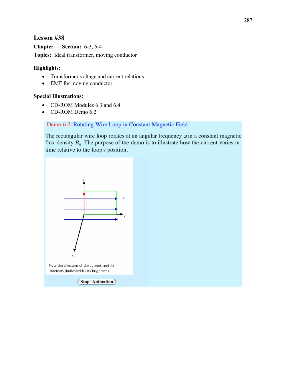
• CD-ROM Demo 6.2
288
Lesson #39
Chapter — Section: 6-5, 6-6
Topics: EM Generator, moving conductor in changing field
Highlights:
• Motor and generator reciprocity
• EMF for combination of motional and transformer
Special Illustrations:
• Technology Brief on “EMF Sensors” (CD-ROM)
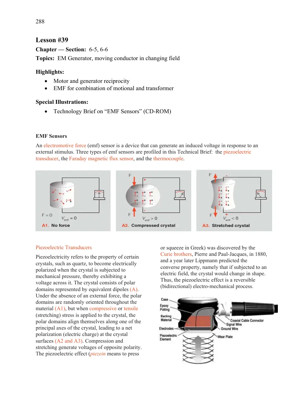
EMF Sensors
An electromotive force (emf) sensor is a device that can generate an induced voltage in response to an
external stimulus. Three types of emf sensors are profiled in this Technical Brief: the piezoelectric
transducer, the Faraday magnetic flux sensor, and the thermocouple.
Piezoelectric Transducers
Piezoelectricity refers to the property of certain
crystals, such as quartz, to become electrically
polarized when the crystal is subjected to
mechanical pressure, thereby exhibiting a
voltage across it. The crystal consists of polar
domains represented by equivalent dipoles (A).
Under the absence of an external force, the polar
domains are randomly oriented throughout the
material (A1), but when compressive or tensile
(stretching) stress is applied to the crystal, the
polar domains align themselves along one of the
principal axes of the crystal, leading to a net
polarization (electric charge) at the crystal
surfaces (A2 and A3). Compression and
stretching generate voltages of opposite polarity.
The piezoelectric effect (piezein means to press
or squeeze in Greek) was discovered by the
Curie brothers, Pierre and Paul-Jacques, in 1880,
and a year later Lippmann predicted the
converse property, namely that if subjected to an
electric field, the crystal would change in shape.
Thus, the piezoelectric effect is a reversible
(bidirectional) electro-mechanical process.
289
Lesson #40
Chapter — Section: 6-7, 6-8
Topics: Displacement current, boundary conditions
Highlights:
• Concept of “displacement current”
• Boundary conditions for the dynamic case
Special Illustrations:
• Example 6-7
290
Lesson #41
Chapter — Section: 6-9, 6-10
Topics: Charge-current continuity, charge dissipation
Highlights:
• Continuity equation
• Relaxation time constant
Special Illustrations:
291
Lesson #42
Chapter — Section: 6-11
Topics: EM potentials
Highlights:
• Retarded potential
• Relation of potentials to fields in the dynamic case
Special Illustrations:
Example 6-8
292
CHAPTER 6
Chapter 6
Sections 6-1 to 6-6: Faraday’s Law and its Applications
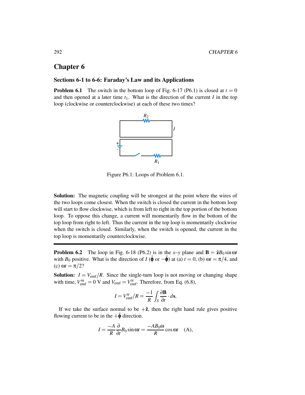
Problem 6.1
The switch in the bottom loop of Fig. 6-17 (P6.1) is closed at t
�
0
and then opened at a later time t1. What is the direction of the current I in the top
loop (clockwise or counterclockwise) at each of these two times?
R2
R1
I
+
-
Figure P6.1: Loops of Problem 6.1.
Solution: The magnetic coupling will be strongest at the point where the wires of
the two loops come closest. When the switch is closed the current in the bottom loop
will start to flow clockwise, which is from left to right in the top portion of the bottom
loop. To oppose this change, a current will momentarily flow in the bottom of the
top loop from right to left. Thus the current in the top loop is momentarily clockwise
when the switch is closed. Similarly, when the switch is opened, the current in the
top loop is momentarily counterclockwise.
Problem 6.2
The loop in Fig. 6-18 (P6.2) is in the x–y plane and B
�
ˆzB0 sinωt
with B0 positive. What is the direction of I (ˆφφφ or
�
ˆφφφ) at (a) t
�
0, (b) ωt
�
π
4, and
(c) ωt
�
π
2?
Solution: I
�
Vemf
R. Since the single-turn loop is not moving or changing shape
with time, V m
emf
�
0 V and Vemf
�
V tr
emf. Therefore, from Eq. (6.8),
I
�
V tr
emf
R
�
� 1
R
�
S
∂B
∂t
� ds
If we take the surface normal to be
�
ˆz, then the right hand rule gives positive
flowing current to be in the
�
ˆφφφ direction.
I
�
� A
R
∂
∂t B0 sinωt
�
� AB0ω
R
cosωt
(A)
�
CHAPTER 6
293
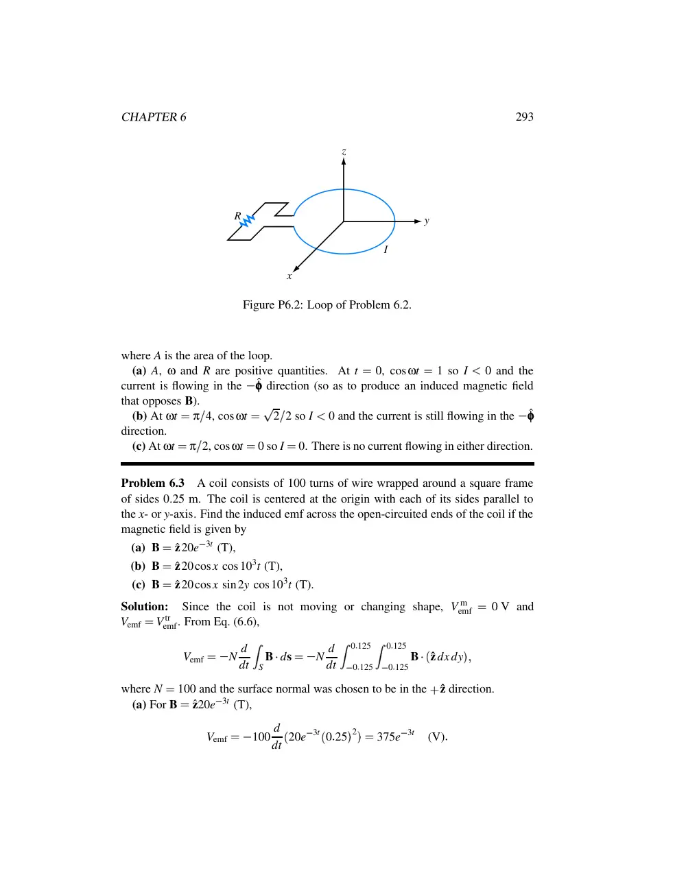
R
z
y
x
I
Figure P6.2: Loop of Problem 6.2.
where A is the area of the loop.
(a) A, ω and R are positive quantities. At t
�
0, cosωt
�
1 so I
�
0 and the
current is flowing in the
�
ˆφφφ direction (so as to produce an induced magnetic field
that opposes B).
(b) At ωt
�
π
4, cosωt
�
� 2
2 so I
�
0 and the current is still flowing in the
�
ˆφφφ
direction.
(c) At ωt
�
π
2, cosωt
�
0 so I
�
0. There is no current flowing in either direction.
Problem 6.3
A coil consists of 100 turns of wire wrapped around a square frame
of sides 0.25 m. The coil is centered at the origin with each of its sides parallel to
the x- or y-axis. Find the induced emf across the open-circuited ends of the coil if the
magnetic field is given by
(a) B
�
ˆz20e
3t (T),
(b) B
�
ˆz20cosx cos103t (T),
(c) B
�
ˆz20cosx sin2y cos103t (T).
Solution:
Since the coil is not moving or changing shape, V m
emf
�
0 V and
Vemf
�
V tr
emf. From Eq. (6.6),
Vemf
�
� N d
dt
�
S B
� ds
�
� N d
dt
�
0
� 125
0
� 125
�
0
� 125
0
� 125 B
�
� ˆzdxdy
�
�
where N
�
100 and the surface normal was chosen to be in the
�
ˆz direction.
(a) For B
�
ˆz20e
3t (T),
Vemf
�
� 100 d
dt
� 20e
3t
� 0
25
� 2
��
375e
3t
(V)
294
CHAPTER 6
(b) For B
�
ˆz20cosxcos103t (T),
Vemf
�
� 100 d
dt
�
20cos103t
�
0
� 125
x
�
0
� 125
�
0
� 125
y
�
0
� 125 cosxdxdy
�
124
6sin103t
(kV)
(c) For B
�
ˆz20cosxsin2ycos103t (T),
Vemf
�
� 100 d
dt
�
20cos103t
�
0
� 125
x
�
0
� 125
�
0
� 125
y
�
0
� 125 cosxsin2ydxdy
�
0
Problem 6.4
A stationary conducting loop with internal resistance of 0.5 Ω is
placed in a time-varying magnetic field. When the loop is closed, a current of 5 A
flows through it. What will the current be if the loop is opened to create a small gap
and a 2-Ω resistor is connected across its open ends?
Solution: Vemf is independent of the resistance which is in the loop. Therefore, when
the loop is intact and the internal resistance is only 0
5 Ω,
Vemf
�
5 A
0
5 Ω
�
2
5 V
When the small gap is created, the total resistance in the loop is infinite and the
current flow is zero. With a 2-Ω resistor in the gap,
I
�
Vemf
� 2 Ω
�
0
5 Ω
��
2
5 V
2
5 Ω
�
1
(A)
Problem 6.5
A circular-loop TV antenna with 0.02 m2 area is in the presence of a
uniform-amplitude 300-MHz signal. When oriented for maximum response, the loop
develops an emf with a peak value of 30 (mV). What is the peak magnitude of B of
the incident wave?
Solution: TV loop antennas have one turn. At maximum orientation, Eq. (6.5)
evaluates to Φ
�
� B
� ds
�
� BA for a loop of area A and a uniform magnetic field
with magnitude B
�
� B
� . Since we know the frequency of the field is f
�
300 MHz,
we can express B as B
�
B0 cos
� ωt
�
α0
� with ω
�
2π
300
106 rad/s and α0 an
arbitrary reference phase. From Eq. (6.6),
Vemf
�
� N dΦ
dt
�
� A d
dt
� B0 cos
� ωt
�
α0
��
�
AB0ωsin
� ωt
�
α0
�
Vemf is maximum when sin
� ωt
�
α0
��
1. Hence,
30
10
3
�
AB0ω
�
0
02
B0
6π
108
�
CHAPTER 6
295
which yields B0
�
0
8 (nA/m).
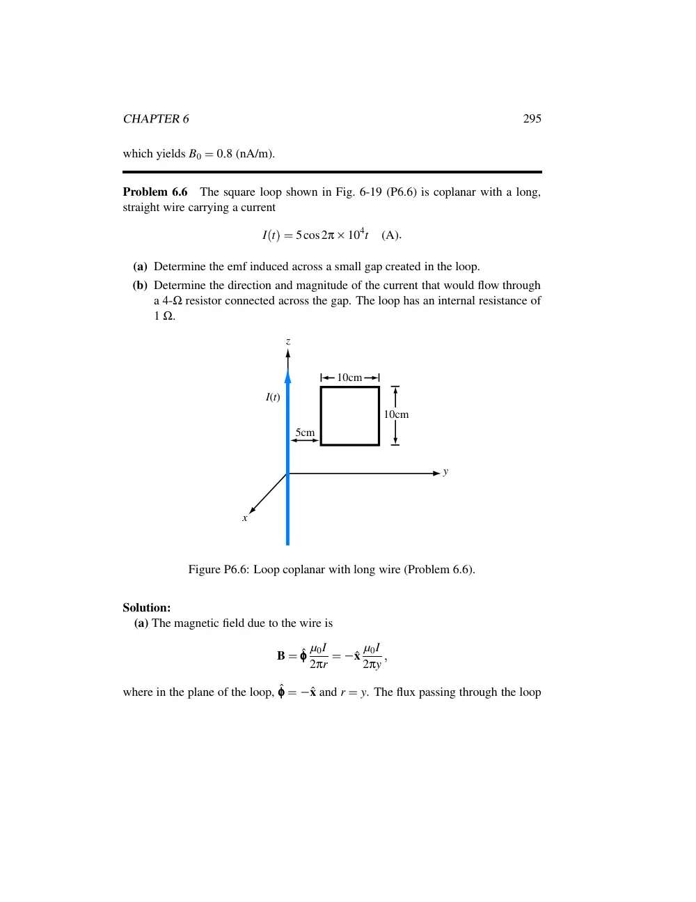
Problem 6.6
The square loop shown in Fig. 6-19 (P6.6) is coplanar with a long,
straight wire carrying a current
I
� t
��
5cos2π
104t
(A)
(a) Determine the emf induced across a small gap created in the loop.
(b) Determine the direction and magnitude of the current that would flow through
a 4-Ω resistor connected across the gap. The loop has an internal resistance of
1 Ω.
y
x
z
5cm
I(t)
10cm
10cm
Figure P6.6: Loop coplanar with long wire (Problem 6.6).
Solution:
(a) The magnetic field due to the wire is
B
�
ˆφφφ µ0I
2πr
�
� ˆx µ0I
2πy
�
where in the plane of the loop, ˆφφφ
�
� ˆx and r
�
y. The flux passing through the loop
296
CHAPTER 6
is
Φ
�
�
S B
� ds
�
�
15 cm
5 cm
�
� ˆx µ0I
2πy
�
�
� ˆx10 (cm)
� dy
�
µ0I
10
1
2π
ln 15
5
�
4π
10
7
5cos
� 2π
104t
��
10
1
2π
1
1
�
1
1
10
7 cos
� 2π
104t
�
(Wb)
Vemf
�
�
dΦ
dt
�
1
1
2π
104 sin
� 2π
104t
��
10
7
�
6
9
10
3 sin
� 2π
104t
�
(V)
(b)
Iind
�
Vemf
4
�
1
�
6
9
10
3
5
sin
� 2π
104t
��
1
38sin
� 2π
104t
�
(mA)
At t
�
0, B is a maximum, it points in
�
ˆx-direction, and since it varies as
cos
� 2π
104t
� , it is decreasing. Hence, the induced current has to be CCW when
looking down on the loop, as shown in the figure.
Problem 6.7
The rectangular conducting loop shown in Fig. 6-20 (P6.7) rotates at
6,000 revolutions per minute in a uniform magnetic flux density given by
B
�
ˆy50
(mT)
Determine the current induced in the loop if its internal resistance is 0
5 Ω.
Solution:
Φ
�
�
S B
� dS
�
ˆy50
10
3
� ˆy
� 2
3
10
4
� cosφ
� t
��
3
10
5 cosφ
� t
�
�
φ
� t
��
ωt
�
2π
6
103
60
t
�
200πt
(rad/s)
�
Φ
�
3
10
5 cos
� 200πt
�
(Wb)
�
Vemf
�
�
dΦ
dt
�
3
10
5
200πsin
� 200πt
��
18
85
10
3 sin
� 200πt
�
(V)
�
Iind
�
Vemf
0
5
�
37
7sin
� 200πt
�
(mA)
CHAPTER 6
297
y
x
z
B
B
ω
φ(t)
3cm
2cm
Figure P6.7: Rotating loop in a magnetic field (Problem 6.7).
The direction of the current is CW (if looking at it along
�
ˆx-direction) when the loop
is in the first quadrant (0
�
φ
�
π
2). The current reverses direction in the second
quadrant, and reverses again every quadrant.
Problem 6.8
A rectangular conducting loop 5 cm
10 cm with a small air gap in
one of its sides is spinning at 7200 revolutions per minute. If the field B is normal to
the loop axis and its magnitude is 6
10
6 T, what is the peak voltage induced across
the air gap?
Solution:
ω
�
2π rad/cycle
7200 cycles/min
60 s/min
�
240π rad/s
�
A
�
5 cm
10 cm
� 100 cm/m
� 2
�
5
0
10
3 m2
From Eqs. (6.36) or (6.38), Vemf
�
AωB0sinωt; it can be seen that the peak voltage is
V peak
emf
�
AωB0
�
5
0
10
3
240π
6
10
6
�
22
62
� µV
�
Problem 6.9
A 50-cm-long metal rod rotates about the z-axis at 90 revolutions per
minute, with end 1 fixed at the origin as shown in Fig. 6-21 (P6.9). Determine the
induced emf V12 if B
�
ˆz2
10
4 T.
Solution: Since B is constant, Vemf
�
V m
emf. The velocity u for any point on the bar
is given by u
�
ˆφφφrω, where
ω
�
2π rad/cycle
� 90 cycles/min
�
� 60 s/min
�
�
3π rad/s
298
CHAPTER 6
ω
1
2
x
y
z
B
Figure P6.9: Rotating rod of Problem 6.9.
From Eq. (6.24),
V12
�
V m
emf
�
�
1
2
� u
B
�
� dl
�
�
0
r
� 0
� 5
� ˆφφφ3πr
ˆz2
10
4
�
� ˆrdr
�
6π
10
4
�
0
r
� 0
� 5 r dr
�
3π
10
4r2
�
�
�
0
0
� 5
�
� 3π
10
4
0
25
�
� 236
� µV
�
Problem 6.10
The loop shown in Fig. 6-22 (P6.10) moves away from a wire
carrying a current I1
�
10 (A) at a constant velocity u
�
ˆy7
5 (m/s). If R
�
10 Ω
and the direction of I2 is as defined in the figure, find I2 as a function of y0, the
distance between the wire and the loop. Ignore the internal resistance of the loop.
Solution: Assume that the wire carrying current I1 is in the same plane as the loop.
The two identical resistors are in series, so I2
�
Vemf
2R, where the induced voltage
is due to motion of the loop and is given by Eq. (6.26):
Vemf
�
V m
emf
�
�
�
C
� u
B
�
� dl
The magnetic field B is created by the wire carrying I1. Choosing ˆz to coincide with
the direction of I1, Eq. (5.30) gives the external magnetic field of a long wire to be
B
�
ˆφφφµ0I1
2πr
CHAPTER 6
299
u
u
I1 = 10 A
I2
20 cm
R
z
R
y0
10 cm
Figure P6.10: Moving loop of Problem 6.10.
For positive values of y0 in the y-z plane, ˆy
�
ˆr, so
u
B
�
ˆy
� u
�
B
�
ˆr
� u
�
ˆφφφµ0I1
2πr
�
ˆzµ0I1u
2πr
Integrating around the four sides of the loop with dl
�
ˆz dz and the limits of
integration chosen in accordance with the assumed direction of I2, and recognizing
that only the two sides without the resistors contribute to V m
emf, we have
V m
emf
�
�
0
� 2
0
�
ˆzµ0I1u
2πr
�
�
�
�
r
� y0
�
� ˆzdz
�
�
�
0
0
� 2
�
ˆzµ0I1u
2πr
�
�
�
�
r
� y0
� 0
� 1
�
� ˆzdz
�
�
4π
10
7
10
7
5
0
2
2π
�
1
y0
�
1
y0
�
0
1
�
3
10
6
�
1
y0
�
1
y0
�
0
1
(V)
�
and therefore
I2
�
V m
emf
2R
�
150
�
1
y0
�
1
y0
�
0
1
(nA)
Problem 6.11
The conducting cylinder shown in Fig. 6-23 (P6.11) rotates about its
axis at 1,200 revolutions per minute in a radial field given by
B
�
ˆr6
(T)
300
CHAPTER 6
z
10cm
+
-
V
5cm
ω
Sliding contact
Figure P6.11: Rotating cylinder in a magnetic field (Problem 6.11).
The cylinder, whose radius is 5 cm and height 10 cm, has sliding contacts at its top
and bottom connected to a voltmeter. Determine the induced voltage.
Solution: The surface of the cylinder has velocity u given by
u
�
ˆφφφωr
�
ˆφφφ2π
1
� 200
60
5
10
2
�
ˆφφφ2π
(m/s)
�
V12
�
�
L
0
� u
B
�
� dl
�
�
0
� 1
0
� ˆφφφ2π
ˆr6
�
� ˆz dz
�
� 3
77
(V)
Problem 6.12
The electromagnetic generator shown in Fig. 6-12 is connected to an
electric bulb with a resistance of 150 Ω. If the loop area is 0.1 m2 and it rotates
at 3,600 revolutions per minute in a uniform magnetic flux density B0
�
0
4 T,
determine the amplitude of the current generated in the light bulb.
Solution: From Eq. (6.38), the sinusoidal voltage generated by the a-c generator is
Vemf
�
AωB0 sin
� ωt
�
C0
��
V0 sin
� ωt
�
C0
� . Hence,
V0
�
AωB0
�
0
1
2π
3
� 600
60
0
4
�
15
08
(V)
�
I
�
V0
R
�
15
08
150
�
0
1
(A)
Problem 6.13
The circular disk shown in Fig. 6-24 (P6.13) lies in the x–y plane
and rotates with uniform angular velocity ω about the z-axis. The disk is of radius a
and is present in a uniform magnetic flux density B
�
ˆzB0. Obtain an expression for
the emf induced at the rim relative to the center of the disk.
CHAPTER 6
301
z
y
x
a
+
- V
ω
Figure P6.13: Rotating circular disk in a magnetic field (Problem 6.13).
y
x
φ
u
r
Figure P6.13: (a) Velocity vector u.
Solution: At a radial distance r, the velocity is
u
�
ˆφφφωr
where φ is the angle in the x–y plane shown in the figure. The induced voltage is
V
�
�
a
0
� u
B
�
� dl
�
�
a
0
�
� ˆφφφωr
�
ˆzB0
�
� ˆr dr
ˆφφφ
ˆz is along ˆr. Hence,
V
�
ωB0
�
a
0 r dr
�
ωB0a2
2
Section 6-7: Displacement Current
Problem 6.14
The plates of a parallel-plate capacitor have areas 10 cm2 each
and are separated by 2 cm. The capacitor is filled with a dielectric material with
302
CHAPTER 6
ε
�
4ε0, and the voltage across it is given by V
� t
�
�
30cos2π
106t (V). Find the
displacement current.
Solution: Since the voltage is of the form given by Eq. (6.46) with V0
�
30 V and
ω
�
2π
106 rad/s, the displacement current is given by Eq. (6.49):
Id
�
�
εA
d V0ωsinωt
�
�
4
8
854
10
12
10
10
4
2
10
2
30
2π
106 sin
� 2π
106t
�
�
� 0
33sin
� 2π
106t
�
(mA)
Problem 6.15
A coaxial capacitor of length l
�
6 cm uses an insulating dielectric
material with εr
�
9. The radii of the cylindrical conductors are 0.5 cm and 1 cm. If
the voltage applied across the capacitor is
V
� t
��
50sin
� 120πt
�
(V)
�
what is the displacement current?
l
r
Id
+
-
V(t)
2a
2b
Figure P6.15:
Solution: To find the displacement current, we need to know E in the dielectric space
between the cylindrical conductors. From Eqs. (4.114) and (4.115),
E
�
� ˆr
Q
2πεrl
�
V
�
Q
2πεl ln
� b
a
Hence,
E
�
� ˆr
V
rln
� b
a
�
�
� ˆr 50sin
� 120πt
�
rln2
�
� ˆr 72
1
r
sin
� 120πt
�
(V/m)
�
CHAPTER 6
303
D
�
εE
�
εrε0E
�
� ˆr9
8
85
10
12
72
1
r
sin
� 120πt
�
�
� ˆr 5
75
10
9
r
sin
� 120πt
�
(C/m2)
The displacement current flows between the conductors through an imaginary
cylindrical surface of length l and radius r.
The current flowing from the outer
conductor to the inner conductor along
� ˆr crosses surface S where
S
�
� ˆr2πrl
Hence,
Id
�
∂D
∂t
� S
�
� ˆr ∂
∂t
� 5
75
10
9
r
sin
� 120πt
�
�
�
� ˆr2πrl
�
�
5
75
10
9
120π
2πl cos
� 120πt
�
�
0
82cos
� 120πt
�
(µA)
Alternatively, since the coaxial capacitor is lossless, its displacement current has to
be equal to the conduction current flowing through the wires connected to the voltage
sources. The capacitance of a coaxial capacitor is given by (4.116) as
C
�
2πεl
ln
� b
a
�
The current is
I
�
C dV
dt
�
2πεl
ln
� b
a
�
� 120π
50cos
� 120πt
��
�
0
82cos
� 120πt
�
(µA)
�
which is the same answer we obtained before.
Problem 6.16
The parallel-plate capacitor shown in Fig. 6-25 (P6.16) is filled
with a lossy dielectric material of relative permittivity εr and conductivity σ. The
separation between the plates is d and each plate is of area A. The capacitor is
connected to a time-varying voltage source V
� t
� .
(a) Obtain an expression for Ic, the conduction current flowing between the plates
inside the capacitor, in terms of the given quantities.
304
CHAPTER 6
+
-
V(t)
I
A
d
ε, σ
Figure P6.16: Parallel-plate capacitor containing a lossy dielectric material (Problem
6.16).
(b) Obtain an expression for Id, the displacement current flowing inside the
capacitor.
(c) Based on your expression for parts (a) and (b), give an equivalent-circuit
representation for the capacitor.
(d) Evaluate the values of the circuit elements for A
�
4 cm2, d
�
0
5 cm, εr
�
4,
σ
�
2
5 (S/m), and V
� t
��
10cos
� 3π
103t
� (V).
Solution:
(a)
R
�
d
σA
�
Ic
�
V
R
�
VσA
d
(b)
E
�
V
d
�
Id
�
∂D
∂t
� A
�
εA ∂E
∂t
�
εA
d
∂V
∂t
(c) The conduction current is directly proportional to V, as characteristic of a
resistor, whereas the displacement current varies as ∂V
∂t, which is characteristic
of a capacitor. Hence,
R
�
d
σA
and
C
�
εA
d
(d)
R
�
0
5
10
2
2
5
4
10
4
�
5 Ω
�
CHAPTER 6
305
+
-
V(t)
I
Id
C
Ic
R
V(t)
+
-
ε, σ
Actual Circuit
Equivalent Circuit
Figure P6.16: (a) Equivalent circuit.
C
�
4
8
85
10
12
4
10
4
0
5
10
2
�
2
84
10
12 F
Problem 6.17
An electromagnetic wave propagating in seawater has an electric
field with a time variation given by E
�
ˆzE0 cosωt. If the permittivity of water is
81ε0 and its conductivity is 4 (S/m), find the ratio of the magnitudes of the conduction
current density to displacement current density at each of the following frequencies:
(a) 1 kHz, (b) 1 MHz, (c) 1 GHz, (d) 100 GHz.
Solution: From Eq. (6.44), the displacement current density is given by
Jd
�
∂
∂t D
�
ε ∂
∂t E
and, from Eq. (4.67), the conduction current is J
�
σE. Converting to phasors and
taking the ratio of the magnitudes,
�
�
�
�
�
�
J
�
Jd
�
�
�
�
�
�
�
�
�
�
�
σ
�
E
jωεrε0
�
E
�
�
�
�
�
�
σ
ωεrε0
(a) At f
�
1 kHz, ω
�
2π
103 rad/s, and
�
�
�
�
�
�
J
�
Jd
�
�
�
�
�
�
4
2π
103
81
8
854
10
12
�
888
103
The displacement current is negligible.
(b) At f
�
1 MHz, ω
�
2π
106 rad/s, and
�
�
�
�
�
�
J
�
Jd
�
�
�
�
�
�
4
2π
106
81
8
854
10
12
�
888
306
CHAPTER 6
The displacement current is practically negligible.
(c) At f
�
1 GHz, ω
�
2π
109 rad/s, and
�
�
�
�
�
�
J
�
Jd
�
�
�
�
�
�
4
2π
109
81
8
854
10
12
�
0
888
Neither the displacement current nor the conduction current are negligible.
(d) At f
�
100 GHz, ω
�
2π
1011 rad/s, and
�
�
�
�
�
�
J
�
Jd
�
�
�
�
�
�
4
2π
1011
81
8
854
10
12
�
8
88
10
3
The conduction current is practically negligible.
Sections 6-9 and 6-10: Continuity Equation and Charge Dissipation
Problem 6.18
At t
�
0, charge density ρv0 was introduced into the interior of a
material with a relative permittivity εr
�
9. If at t
�
1 µs the charge density has
dissipated down to 10
3ρv0, what is the conductivity of the material?
Solution: We start by using Eq. (6.61) to find τr:
ρv
� t
��
ρv0e
t
� τr
�
or
10
3ρv0
�
ρv0e
10
� 6
� τr
�
which gives
ln10
3
�
�
10
6
τr
�
or
τr
�
�
10
6
ln10
3
�
1
45
10
7
(s)
But τr
�
ε
σ
�
9ε0
σ. Hence
σ
�
9ε0
τr
�
9
8
854
10
12
1
45
10
7
�
5
5
10
4
(S/m)
CHAPTER 6
307
Problem 6.19
If the current density in a conducting medium is given by
J
� x
� y
� z;t
�
�
� ˆxz2
�
ˆy4y2
�
ˆz2x
� cosωt
�
determine the corresponding charge distribution ρv
� x
� y
� z;t
� .
Solution: Eq. (6.58) is given by
∇
� J
�
�
∂ρv
∂t
(24)
The divergence of J is
∇
� J
�
�
ˆx ∂
∂x
�
ˆy ∂
∂y
�
ˆz ∂
∂z
�
� ˆxz2
�
ˆy4y2
�
ˆz2x
� cosωt
�
� 4 ∂
∂y
� y2 cosωt
��
� 8ycosωt
Using this result in Eq. (24) and then integrating both sides with respect to t gives
ρv
�
�
�
� ∇
� J
� dt
�
�
�
�
8ycosωt dt
�
8y
ω sinωt
�
C0
�
where C0 is a constant of integration.
Problem 6.20
In a certain medium, the direction of current density J points in the
radial direction in cylindrical coordinates and its magnitude is independent of both φ
and z. Determine J, given that the charge density in the medium is
ρv
�
ρ0rcosωt
� C/m3
�
Solution: Based on the given information,
J
�
ˆrJr
� r
�
With Jφ
�
Jz
�
0, in cylindrical coordinates the divergence is given by
∇
� J
�
1
r
∂
∂r
� rJr
�
From Eq. (6.54),
∇
� J
�
�
∂ρv
∂t
�
�
∂
∂t
� ρ0rcosωt
��
ρ0rωsinωt
308
CHAPTER 6
Hence
1
r
∂
∂r
� rJr
��
ρ0rωsinωt
�
∂
∂r
� rJr
��
ρ0r2ωsinωt
�
�
r
0
∂
∂r
� rJr
� dr
�
ρ0ωsinωt
�
r
0 r2 dr
�
rJr
� r
0
�
� ρ0ωsinωt
� r3
3
�
�
�
�
r
0
�
Jr
�
ρ0ωr2
3
sinωt
�
and
J
�
ˆrJr
�
ˆr ρ0ωr2
3
sinωt
(A/m2)
Problem 6.21
If we were to characterize how good a material is as an insulator by
its resistance to dissipating charge, which of the following two materials is the better
insulator?
Dry Soil:
εr
�
2
5,
σ
�
10
4 (S/m)
Fresh Water:
εr
�
80,
σ
�
10
3 (S/m)
Solution: Relaxation time constant τr
�
ε
σ .
For dry soil,
τr
�
2
5
10
4
�
2
5
104 s.
For fresh water,
τr
�
80
10
3
�
8
104 s.
Since it takes longer for charge to dissipate in fresh water, it is a better insulator than
dry soil.
Sections 6-11: Electromagnetic Potentials
Problem 6.22
The electric field of an electromagnetic wave propagating in air is
given by
E
� z
� t
��
ˆx4cos
� 6
108t
�
2z
�
�
ˆy3sin
� 6
108t
�
2z
�
(V/m)
CHAPTER 6
309
Find the associated magnetic field H
� z
� t
� .
Solution: Converting to phasor form, the electric field is given by
�
E
� z
��
ˆx4e
j2z
�
jˆy3e
j2z
(V/m)
�
which can be used with Eq. (6.87) to find the magnetic field:
�
H
� z
��
1
�
jωµ∇
�
E
�
1
�
jωµ
�
�
�
�
�
�
ˆx
ˆy
ˆz
∂
∂x
∂
∂y
∂
∂z
4e
j2z
�
j3e
j2z
0
�
�
�
�
�
�
�
1
�
jωµ
� ˆx6e
j2z
�
ˆyj8e
j2z
�
�
j
6
108
4π
10
7
� ˆx6
�
ˆyj8
� e
j2z
�
jˆx8
0e
j2z
�
ˆy10
6e
j2z
(mA/m)
Converting back to instantaneous values, this is
H
� t
� z
��
� ˆx8
0sin
� 6
108t
�
2z
�
�
ˆy10
6cos
� 6
108t
�
2z
�
(mA/m)
Problem 6.23
The magnetic field in a dielectric material with ε
�
4ε0, µ
�
µ0, and
σ
�
0 is given by
H
� y
� t
��
ˆx5cos
� 2π
107t
�
ky
�
(A/m)
Find k and the associated electric field E.
Solution: In phasor form, the magnetic field is given by
�
H
�
ˆx5ejky (A/m). From
Eq. (6.86),
�
E
�
1
jωε∇
�
H
�
�
jk
jωε ˆz5ejky
and, from Eq. (6.87),
�
H
�
1
�
jωµ∇
�
E
�
�
jk2
�
jω2εµ ˆx5ejky
�
which, together with the original phasor expression for
�
H, implies that
k
�
ω
� εµ
�
ω
� εr
c
�
2π
107
� 4
3
108
�
4π
30
(rad/m)
310
CHAPTER 6
Inserting this value in the expression for
�
E above,
�
E
�
� ˆz
4π
30
2π
107
4
8
854
10
12 5ej4πy
� 30
�
� ˆz941e j4πy
� 30
(V/m)
Problem 6.24
Given an electric field
E
�
ˆxE0 sinaycos
� ωt
�
kz
�
�
where E0, a, ω, and k are constants, find H.
Solution:
E
�
ˆxE0 sinaycos
� ωt
�
kz
�
�
�
E
�
ˆxE0 sinaye
jkz
�
�
H
�
�
1
jωµ ∇
�
E
�
�
1
jωµ
�
ˆy ∂
∂z
� E0 sinaye
jkz
�
�
ˆz ∂
∂y
� E0 sinaye
jkz
�
�
�
E0
ωµ
� ˆyksinay
�
ˆz jacosay � e
jkz
�
H
�
��
�
�
Hejωt
�
�
��
�
E0
ωµ
� ˆyksinay
�
ˆzacosaye
jπ
� 2
� e
jkzejωt
�
�
E0
ωµ
� ˆyksinaycos
� ωt
�
kz
�
�
ˆzacosaycos
ωt
�
kz
�
π
2
�
�
E0
ωµ
� ˆyksinaycos
� ωt
�
kz
�
�
ˆzacosaysin
� ωt
�
kz
��
Problem 6.25
The electric field radiated by a short dipole antenna is given in
spherical coordinates by
E
� R
� θ;t
��
ˆθθθ2
10
2
R
sinθ cos
� 6π
108t
�
2πR
�
(V/m)
Find H
� R
� θ;t
� .
Solution: Converting to phasor form, the electric field is given by
�
E
� R
� θ
��
ˆθθθEθ
�
ˆθθθ2
10
2
R
sinθe
j2πR
(V/m)
�
CHAPTER 6
311
which can be used with Eq. (6.87) to find the magnetic field:
�
H
� R
� θ
��
1
�
jωµ∇
�
E
�
1
�
jωµ
�
ˆR
1
Rsinθ
∂Eθ
∂φ
�
ˆφφφ1
R
∂
∂R
� REθ
�
�
�
1
�
jωµ
ˆφφφ 2
10
2
R
sinθ ∂
∂R
� e
j2πR
�
�
ˆφφφ
2π
6π
108
4π
10
7
2
10
2
R
sinθe
j2πR
�
ˆφφφ 53
R sinθe
j2πR
(µA/m)
Converting back to instantaneous value, this is
H
� R
� θ;t
��
ˆφφφ 53
R sinθcos
� 6π
108t
�
2πR
�
(µA/m)
Problem 6.26
A Hertzian dipole is a short conducting wire carrying an
approximately constant current over its length l. If such a dipole is placed along
the z-axis with its midpoint at the origin and if the current flowing through it is
i
� t
��
I0 cosωt, find
(a) the retarded vector potential
�
A
� R
� θ
� φ
� at an observation point Q
� R
� θ
� φ
� in a
spherical coordinate system, and
(b) the magnetic field phasor
�
H
� R
� θ
� φ
� .
Assume l to be sufficiently small so that the observation point is approximately
equidistant to all points on the dipole; that is, assume that R
�
�
R.
Solution:
(a) In phasor form, the current is given by
�
I
�
I0. Explicitly writing the volume
integral in Eq. (6.84) as a double integral over the wire cross section and a single
integral over its length,
�
A
�
µ
4π
�
l
� 2
l
� 2
�
�
s
�
J
� Ri
� e
jkR
�
R
�
dsdz
�
where s is the wire cross section. The wire is infinitesimally thin, so that R
� is not a
function of x or y and the integration over the cross section of the wire applies only to
the current density. Recognizing that
�
J
�
ˆzI0
s, and employing the relation R
�
�
R,
�
A
�
ˆzµI0
4π
�
l
� 2
l
� 2
e
jkR
�
R
�
dz
�
ˆzµI0
4π
�
l
� 2
l
� 2
e
jkR
R
dz
�
ˆz µI0l
4πRe
jkR
312
CHAPTER 6
In spherical coordinates, ˆz
�
ˆRcosθ
�
ˆθθθsinθ, and therefore
�
A
�
� ˆRcosθ
�
ˆθθθsinθ
� µI0l
4πRe
jkR
(b) From Eq. (6.85),
�
H
�
1
µ∇
�
A
�
I0l
4π∇
�
� ˆRcosθ
�
ˆθθθsinθ
� e
jkR
R
�
�
I0l
4π
ˆφφφ 1
R
�
∂
∂R
�
sinθe
jkR
�
∂
∂θ
�
cosθe
jkR
R
�
ˆφφφ I0l sinθe
jkR
4πR
�
jk
�
1
R
Problem 6.27
The magnetic field in a given dielectric medium is given by
H
�
ˆy6cos2zsin
� 2
107t
�
0
1x
�
(A/m)
�
where x and z are in meters. Determine:
(a) E,
(b) the displacement current density Jd, and
(c) the charge density ρv.
Solution:
(a)
H
�
ˆy6cos2zsin
� 2
107t
�
0
1x
��
ˆy6cos2zcos
� 2
107t
�
0
1x
�
π
2
�
�
�
H
�
ˆy6cos2ze
j0
� 1xe
jπ
� 2
�
� ˆy j6cos2ze
j0
� 1x
�
�
E
�
1
jωε ∇
�
H
�
1
jωε
�
�
�
�
�
�
ˆx
ˆy
ˆz
∂
∂x
∂
∂y
∂
∂z
0
�
j6cos2ze
j0
� 1x
0
�
�
�
�
�
�
�
1
jωε
�
ˆx
�
�
∂
∂z
�
�
j6cos2ze
j0
� 1x
�
�
�
ˆz
� ∂
∂x
�
�
j6cos2ze
j0
� 1x
�
�
�
�
ˆx
�
�
12
ωε sin2ze
j0
� 1x
�
ˆz
�
j0
6
ωε cos2ze
j0
� 1x
From the given expression for H,
ω
�
2
107
(rad/s)
�
CHAPTER 6
313
β
�
0
1
(rad/m)
Hence,
up
�
ω
β
�
2
108
(m/s)
�
and
εr
�
�
c
up
2
�
� 3
108
2
108
2
�
2
25
Using the values for ω and ε, we have
�
E
�
�
� ˆx30sin2z
�
ˆz j1
5cos2z
��
103e
j0
� 1x
(V/m)
�
E
�
�
� ˆx30sin2zcos
� 2
107t
�
0
1x
�
�
ˆz1
5cos2zsin
� 2
107t
�
0
1x
�
�
(kV/m)
(b)
�
D
�
ε
�
E
�
εrε0
�
E
�
�
�
ˆx0
6sin2z
�
ˆz j0
03cos2z
��
10
6e
j0
� 1x
(C/m2)
�
Jd
�
∂D
∂t
�
or
�
Jd
�
jω
�
D
�
�
� ˆx j12sin2z
�
ˆz0
6cos2z
� e
j0
� 1x
�
Jd
�
��
�
�
Jdejωt
�
�
�
ˆx12sin2zsin
� 2
107t
�
0
1x
�
�
ˆz0
6cos2zcos
� 2
107t
�
0
1x
�
�
(A/m2)
(c) We can find ρv from
∇
� D
�
ρv
or from
∇
� J
�
�
∂ρv
∂t
Applying Maxwell’s equation,
ρv
�
∇
� D
�
ε∇
� E
�
εrε0
� ∂Ex
∂x
�
∂Ez
∂z
yields
ρv
�
εrε0
�
∂
∂x
�
� 30sin2zcos
� 2
107t
�
0
1x
��
�
∂
∂z
�
� 1
5cos2zsin
� 2
107t
�
0
1x
�
�
�
�
εrε0
�
� 3sin2zsin
� 2
107t
�
0
1x
�
�
3sin2zsin
� 2
107t
�
0
1x
�
�
�
0
314
CHAPTER 6
Problem 6.28
The transformer shown in the figure consists of a long wire
coincident with the z-axis carrying a current I
�
I0 cosωt, coupling magnetic energy
to a toroidal coil situated in the x–y plane and centered at the origin. The toroidal core
uses iron material with relative permeability µr, around which 100 turns of a tightly
wound coil serves to induce a voltage Vemf, as shown in the figure.
a
b
x
y
z
I
Vemf
c
N
+
-
Iron core with µr
(a) Develop an expression for Vemf.
(b) Calculate Vemf for f
�
60 Hz, µr
�
4000, a
�
5 cm, b
�
6 cm, c
�
2 cm, and
I0
�
50 A.
Solution:
(a) We start by calculating the magnetic flux through the coil, noting that r, the
distance from the wire varies from a to b
Φ
�
�
S B
� ds
�
�
b
a
ˆx µI
2πr
� ˆxc dr
�
µcI
2π ln
� b
a
Vemf
�
� N dΦ
dt
�
�
µcN
2π ln
� b
a
dI
dt
�
µcNωI0
2π
ln
� b
a
sinωt
(V)
CHAPTER 6
315
(b)
Vemf
�
4000
4π
10
7
2
10
2
100
2π
60
50ln
� 6
5
�
2π
sin377t
�
5
5sin377t
(V)
Problem 6.29
In wet soil, characterized by σ
�
10
2 (S/m), µr
�
1, and εr
�
36,
at what frequency is the conduction current density equal in magnitude to the
displacement current density?
Solution: For sinusoidal wave variation, the phasor electric field is
E
�
E0ejωt
Jc
�
σE
�
σE0ejωt
Jd
�
∂D
∂t
�
ε∂E
∂t
�
jωεE0ejωt
�
�
�
�
Jc
Jd
�
�
�
�
�
1
�
σ
ωε
�
σ
2πε f
or
f
�
σ
2πε
�
10
2
2π
36
8
85
10
12
�
5
106
�
5 MHz
Problem 6.30
In free space, the magnetic field is given by
H
�
ˆφφφ 36
r cos
� 6
109t
�
kz
�
(mA/m)
(a) Determine k.
(b) Determine E.
(c) Determine Jd.
Solution:
(a) From the given expression, ω
�
6
109 (rad/s), and since the medium is free
space,
k
�
ω
c
�
6
109
3
108
�
20
(rad/m)
316
CHAPTER 6
(b) Convert H to phasor:
�
H
�
ˆφφφ 36
r e
jkz
(mA/m)
�
E
�
1
jωε0
∇
�
H
�
1
jωε0
�
� ˆr ∂Hφ
∂z
�
ˆz 1
r
∂
∂r
� rHφ
�
�
�
1
jωε0
�
� ˆr ∂
∂z
� 36
r e
jkz
�
ˆz
r
∂
∂r
� 36e
jkz
�
�
�
1
jωε0
�
ˆr j36k
r
e
jkz
�
�
ˆr 36k
ωε0r e
jkz
�
ˆr 36
377
r
e
jkz
10
3
�
ˆr 13
6
r
e
j20z
(V/m)
E
�
��
�
�
Eejωt
�
�
ˆr 13
6
r
cos
� 6
109t
�
20z
�
(V/m)
(c)
Jd
�
ε0
∂E
∂t
�
ˆr 13
6
r
ε0
∂
∂t
� cos
� 6
109t
�
20z
�
�
�
� ˆr 13
6ε0
6
109
r
sin
� 6
109t
�
20z
�
(A/m2)
�
� ˆr 0
72
r
sin
� 6
109t
�
20z
�
(A/m2)