
EECE 380 Problems Solution Manual, Fall 2011
American University of Beirut · Engineering Electromagnetics · 82 pages · with solution
Showing the first 10 of 82 pages. Download the PDF to see all of it.
More EECE 380 files
- Problems Solution Manual · Fall 2011Problems · with solutionView
- Problems Solution Manual · Fall 2011Problems · with solutionView
- Problems Solution Manual · Fall 2011Problems · with solutionView
- Problems Solution Manual · Fall 2011Problems · with solutionView
- Problems Solution Manual · Fall 2011Problems · with solutionView
- Problems Solution Manual · Fall 2011Problems · with solutionView
- Problems Solution Manual · Fall 2011Problems · with solutionView
- Problems · Spring 2008ProblemsView
Show the text of this problems
25
Chapter 2: Transmission Lines
Lesson #4
Chapter — Section: 2-1, 2-2
Topics: Lumped-element model
Highlights:
• TEM lines
• General properties of transmission lines
• L, C, R, G
26
Lesson #5
Chapter — Section: 2-3, 2-4
Topics: Transmission-line equations, wave propagation
Highlights:
• Wave equation
• Characteristic impedance
• General solution
Special Illustrations:
• Example 2-1
27
Lesson #6
Chapter — Section: 2-5
Topics: Lossless line
Highlights:
• General wave propagation properties
• Reflection coefficient
• Standing waves
• Maxima and minima
Special Illustrations:
• Example 2-2
• Example 2-5
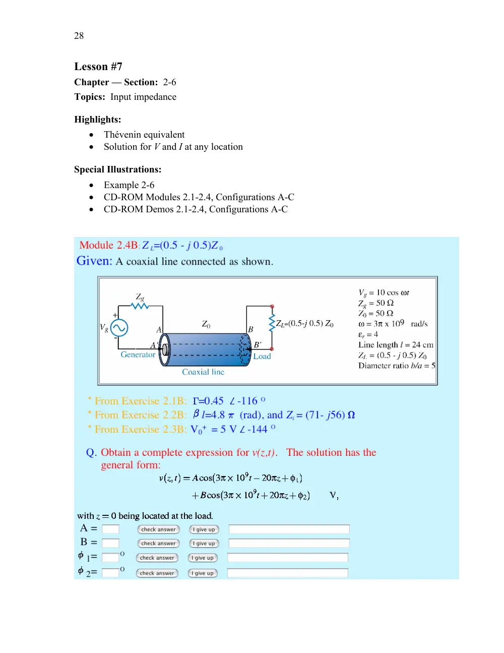
28
Lesson #7
Chapter — Section: 2-6
Topics: Input impedance
Highlights:
• Thévenin equivalent
• Solution for V and I at any location
Special Illustrations:
• Example 2-6
• CD-ROM Modules 2.1-2.4, Configurations A-C
• CD-ROM Demos 2.1-2.4, Configurations A-C
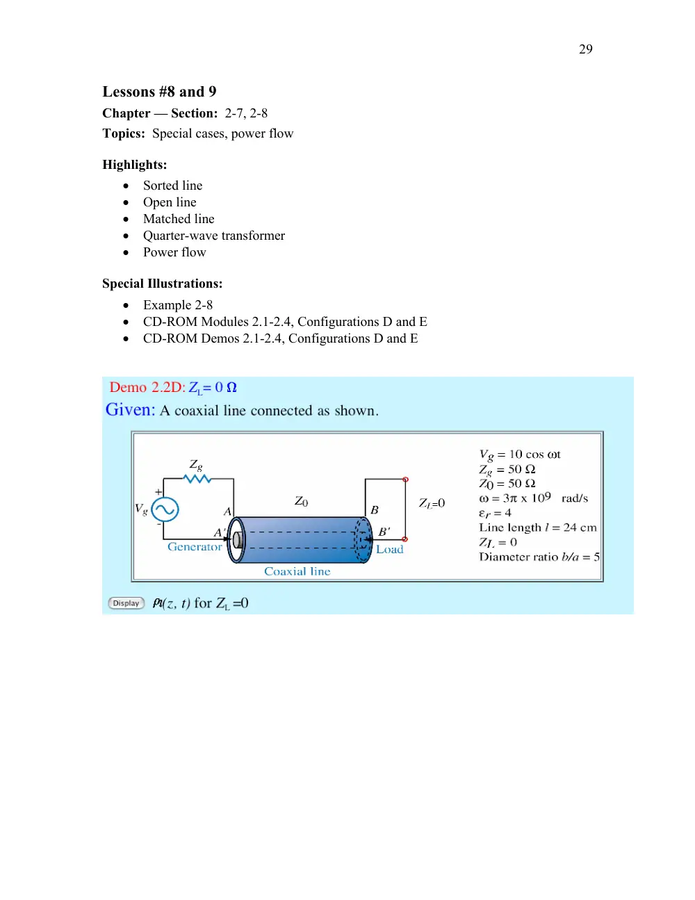
29
Lessons #8 and 9
Chapter — Section: 2-7, 2-8
Topics: Special cases, power flow
Highlights:
• Sorted line
• Open line
• Matched line
• Quarter-wave transformer
• Power flow
Special Illustrations:
• Example 2-8
• CD-ROM Modules 2.1-2.4, Configurations D and E
• CD-ROM Demos 2.1-2.4, Configurations D and E
30
Lessons #10 and 11
Chapter — Section: 2-9
Topics: Smith chart
Highlights:
• Structure of Smith chart
• Calculating impedances, admittances, transformations
• Locations of maxima and minima
Special Illustrations:
• Example 2-10
• Example 2-11
31
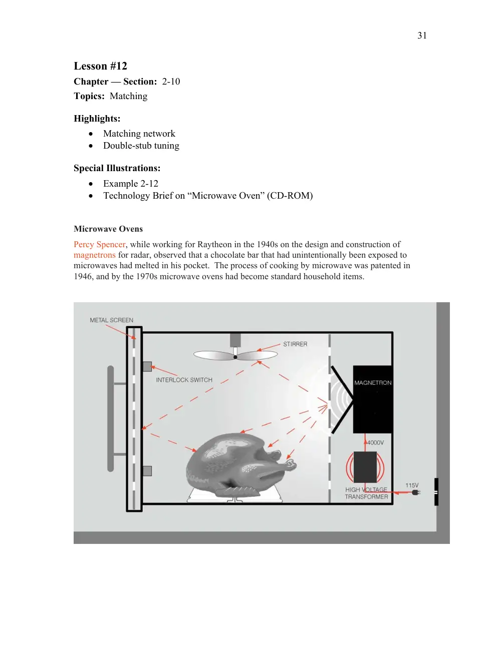
Lesson #12
Chapter — Section: 2-10
Topics: Matching
Highlights:
• Matching network
• Double-stub tuning
Special Illustrations:
• Example 2-12
• Technology Brief on “Microwave Oven” (CD-ROM)
Microwave Ovens
Percy Spencer, while working for Raytheon in the 1940s on the design and construction of
magnetrons for radar, observed that a chocolate bar that had unintentionally been exposed to
microwaves had melted in his pocket. The process of cooking by microwave was patented in
1946, and by the 1970s microwave ovens had become standard household items.
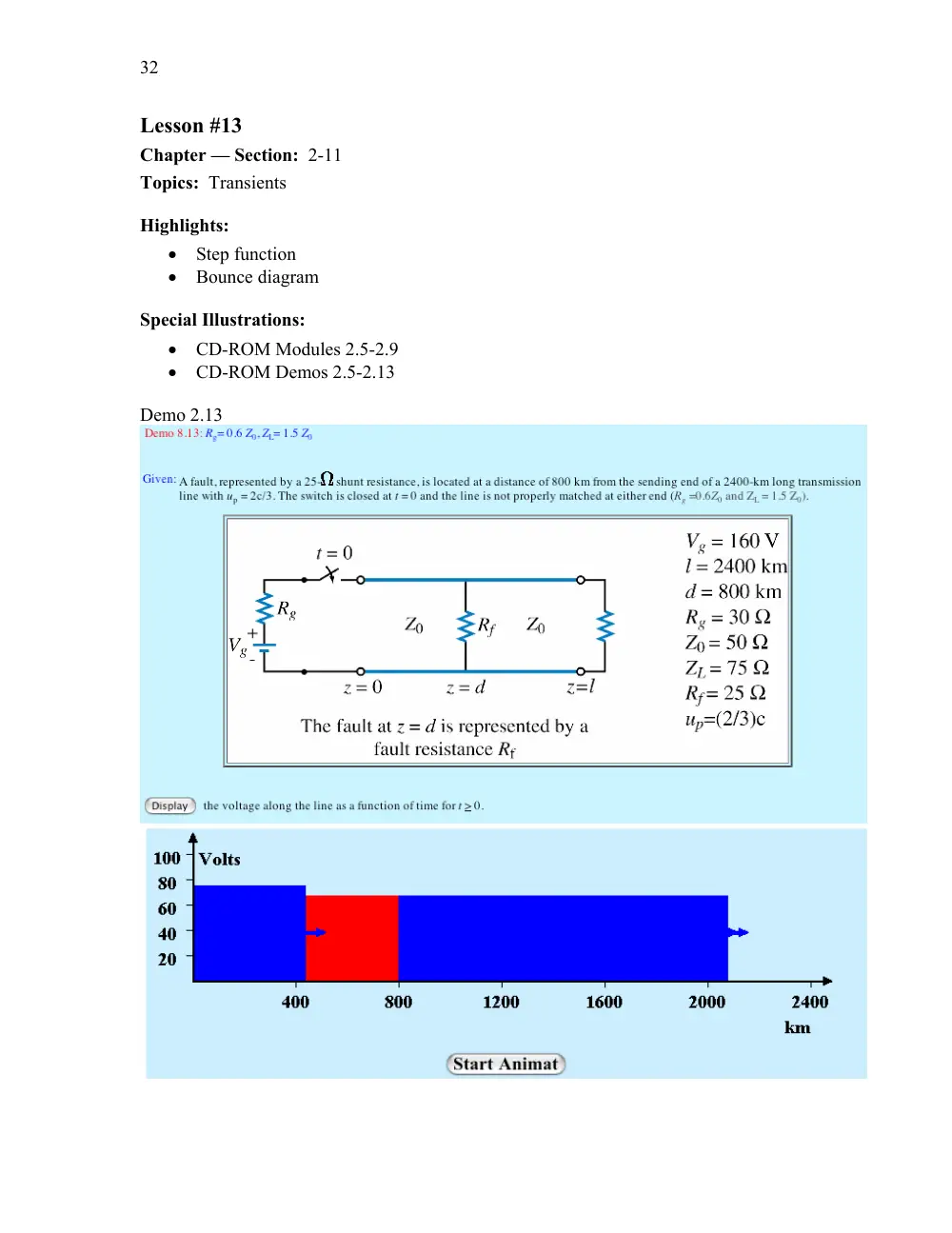
32
Lesson #13
Chapter — Section: 2-11
Topics: Transients
Highlights:
• Step function
• Bounce diagram
Special Illustrations:
• CD-ROM Modules 2.5-2.9
• CD-ROM Demos 2.5-2.13
Demo 2.13
CHAPTER 2
33
Chapter 2
Sections 2-1 to 2-4: Transmission-Line Model
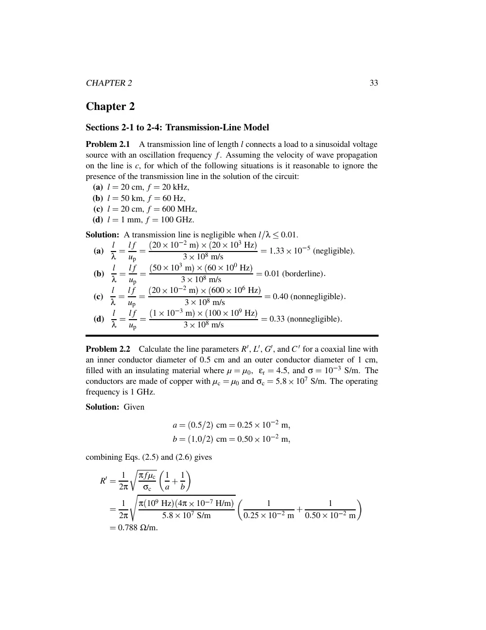
Problem 2.1
A transmission line of length l connects a load to a sinusoidal voltage
source with an oscillation frequency f. Assuming the velocity of wave propagation
on the line is c, for which of the following situations is it reasonable to ignore the
presence of the transmission line in the solution of the circuit:
(a) l
�
20 cm, f
�
20 kHz,
(b) l
�
50 km, f
�
60 Hz,
(c) l
�
20 cm, f
�
600 MHz,
(d) l
�
1 mm, f
�
100 GHz.
Solution: A transmission line is negligible when l
λ
�
0
01.
(a)
l
λ
�
l f
up
�
� 20
10
2 m
��
� 20
103 Hz
�
3
108 m/s
�
1
33
10
5 (negligible).
(b)
l
λ
�
l f
up
�
� 50
103 m
��
� 60
100 Hz
�
3
108 m/s
�
0
01 (borderline)
(c)
l
λ
�
l f
up
�
� 20
10
2 m
��
� 600
106 Hz
�
3
108 m/s
�
0
40 (nonnegligible)
(d)
l
λ
�
l f
up
�
� 1
10
3 m
��
� 100
109 Hz
�
3
108 m/s
�
0
33 (nonnegligible)
Problem 2.2
Calculate the line parameters R
� , L
� , G
� , and C
� for a coaxial line with
an inner conductor diameter of 0
5 cm and an outer conductor diameter of 1 cm,
filled with an insulating material where µ
�
µ0, εr
�
4
5, and σ
�
10
3 S/m. The
conductors are made of copper with µc
�
µ0 and σc
�
5
8
107 S/m. The operating
frequency is 1 GHz.
Solution: Given
a
�
� 0
5
2
� cm
�
0
25
10
2 m
�
b
�
� 1
0
2
� cm
�
0
50
10
2 m
�
combining Eqs. (2.5) and (2.6) gives
R
�
�
1
2π
�
π fµc
σc
� 1
a
�
1
b
�
1
2π
π
� 109 Hz
�
� 4π
10
7 H/m
�
5
8
107 S/m
�
1
0
25
10
2 m
�
1
0
50
10
2 m
�
0
788 Ω/m
34
CHAPTER 2
From Eq. (2.7),
L
�
�
µ
2π ln
� b
a
�
4π
10
7 H/m
2π
ln2
�
139 nH/m
From Eq. (2.8),
G
�
�
2πσ
ln
� b
a
�
�
2π
10
3 S/m
ln2
�
9
1 mS/m
From Eq. (2.9),
C
�
�
2πε
ln
� b
a
�
�
2πεrε0
ln
� b
a
�
�
2π
4
5
� 8
854
10
12 F/m
�
ln2
�
362 pF/m
Problem 2.3
A 1-GHz parallel-plate transmission line consists of 1.2-cm-wide
copper strips separated by a 0.15-cm-thick layer of polystyrene. Appendix B gives
µc
�
µ0
�
4π
10
7 (H/m) and σc
�
5
8
107 (S/m) for copper, and εr
�
2
6 for
polystyrene. Use Table 2-1 to determine the line parameters of the transmission line.
Assume µ
�
µ0 and σ
�
0 for polystyrene.
Solution:
R
�
�
2Rs
w
�
2
w
�
π fµc
σc
�
2
1
2
10
2
� π
109
4π
10
7
5
8
107
1
� 2
�
1
38
(Ω/m)
�
L
�
�
µd
w
�
4π
10
7
1
5
10
3
1
2
10
2
�
1
57
10
7
(H/m)
�
G
�
�
0
because σ
�
0
�
C
�
�
εw
d
�
ε0εr
w
d
�
10
9
36π
2
6
1
2
10
2
1
5
10
3
�
1
84
10
10
(F/m)
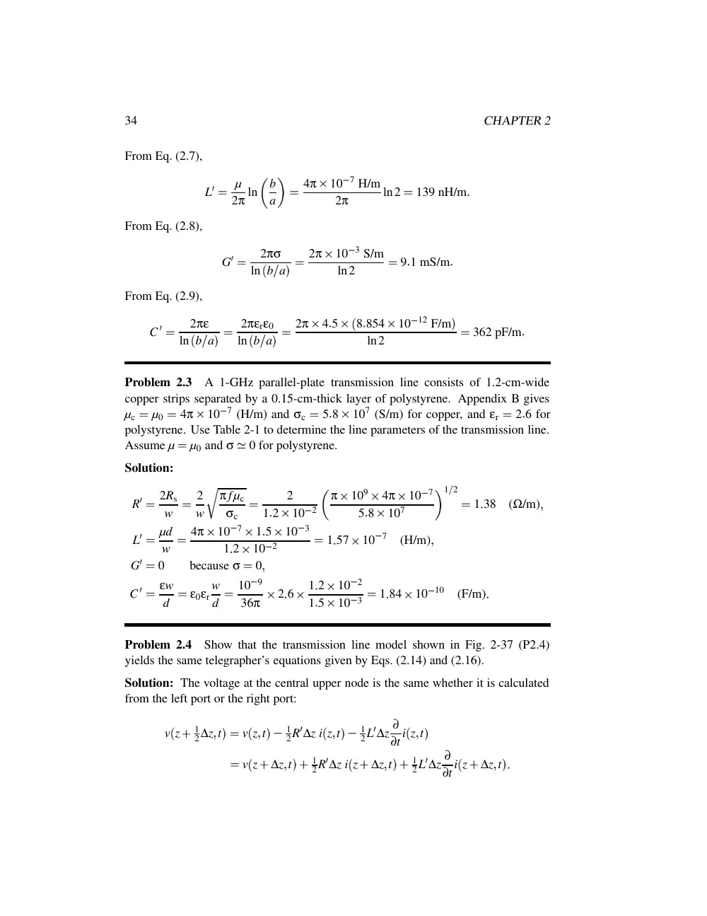
Problem 2.4
Show that the transmission line model shown in Fig. 2-37 (P2.4)
yields the same telegrapher’s equations given by Eqs. (2.14) and (2.16).
Solution: The voltage at the central upper node is the same whether it is calculated
from the left port or the right port:
v
� z
�
1
2∆z
� t
��
v
� z
� t
�
�
1
2R
� ∆z i
� z
� t
�
�
1
2L
� ∆z ∂
∂t i
� z
� t
�
�
v
� z
�
∆z
� t
�
�
1
2R
� ∆z i
� z
�
∆z
� t
�
�
1
2L
� ∆z ∂
∂t i
� z
�
∆z
� t
�
CHAPTER 2
35
G'∆z
C'∆z
∆z
R'∆z
2
L'∆z
2
R'∆z
2
L'∆z
2
i(z, t)
+
-
+
-
i(z+∆z, t)
v(z, t)
v(z+∆z, t)
Figure P2.4: Transmission line model.
Recognizing that the current through the G
�
� C
� branch is i
� z
� t
�
�
i
� z
�
∆z
� t
� (from
Kirchhoff’s current law), we can conclude that
i
� z
� t
�
�
i
� z
�
∆z
� t
��
G
� ∆z v
� z
�
1
2∆z
� t
�
�
C
� ∆z ∂
∂t v
� z
�
1
2∆z
� t
�
From both of these equations, the proof is completed by following the steps outlined
in the text, ie. rearranging terms, dividing by ∆z, and taking the limit as ∆z
�
0.
Problem 2.5
Find α
� β
� up, and Z0 for the coaxial line of Problem 2.2.
Solution: From Eq. (2.22),
γ
�
�
� R
�
�
jωL
�
�
� G
�
�
jωC
�
�
�
�
� 0
788 Ω/m
�
�
j
� 2π
109 s
1
�
� 139
10
9 H/m
�
�
� 9
1
10
3 S/m
�
�
j
� 2π
109 s
1
�
� 362
10
12 F/m
�
�
� 109
10
3
�
j44
5
� m
1
Thus, from Eqs. (2.25a) and (2.25b), α
�
0
109 Np/m and β
�
44
5 rad/m.
From Eq. (2.29),
Z0
�
R
�
�
jωL
�
G
�
�
jωC
�
�
� 0
788 Ω/m
�
�
j
� 2π
109 s
1
�
� 139
10
9 H/m
�
� 9
1
10
3 S/m
�
�
j
� 2π
109 s
1
�
� 362
10
12 F/m
�
�
� 19
6
�
j0
030
� Ω
From Eq. (2.33),
up
�
ω
β
�
2π
109
44
5
�
1
41
108 m/s
36
CHAPTER 2
Section 2-5: The Lossless Line
Problem 2.6
In addition to not dissipating power, a lossless line has two important
features:
(1) it is dispertionless (µp is independent of frequency) and (2) its
characteristic impedance Z0 is purely real. Sometimes, it is not possible to design
a transmission line such that R
��
ωL
� and G
��
ωC
� , but it is possible to choose the
dimensions of the line and its material properties so as to satisfy the condition
R
� C
�
�
L
� G
�
(distortionless line)
Such a line is called a distortionless line because despite the fact that it is not lossless,
it does nonetheless possess the previously mentioned features of the loss line. Show
that for a distortionless line,
α
�
R
�
�
C
�
L
�
�
� R
� G
�
�
β
�
ω
� L
� C
�
�
Z0
�
�
L
�
C
�
Solution: Using the distortionless condition in Eq. (2.22) gives
γ
�
α
�
jβ
�
�
� R
�
�
jωL
�
�
� G
�
�
jωC
�
�
�
� L
� C
�
� R
�
L
�
�
jω
� G
�
C
�
�
jω
�
� L
� C
�
� R
�
L
�
�
jω
� R
�
L
�
�
jω
�
� L
� C
�
� R
�
L
�
�
jω
�
R
�
�
C
�
L
�
�
jω
� L
� C
�
Hence,
α
�
��
� γ
��
R
�
�
C
�
L
�
�
β
�
��
� γ
��
ω
� L
� C
�
�
up
�
ω
β
�
1
� L
� C
�
Similarly, using the distortionless condition in Eq. (2.29) gives
Z0
�
R
�
�
jωL
�
G
�
�
jωC
�
�
�
L
�
C
�
R
�
L
�
�
jω
G
�
C
�
�
jω
�
�
L
�
C
�
Problem 2.7
For a distortionless line with Z0
�
50 Ω,
α
�
20 (mNp/m),
up
�
2
5
108 (m/s), find the line parameters and λ at 100 MHz.
CHAPTER 2
37
Solution: The product of the expressions for α and Z0 given in Problem 2.6 gives
R
�
�
αZ0
�
20
10
3
50
�
1
(Ω/m)
�
and taking the ratio of the expression for Z0 to that for up
�
ω
β
�
1
� L
� C
� gives
L
�
�
Z0
up
�
50
2
5
108
�
2
10
7 (H/m)
�
200
(nH/m)
With L
� known, we use the expression for Z0 to find C
� :
C
�
�
L
�
Z2
0
�
2
10
7
� 50
� 2
�
8
10
11 (F/m)
�
80
(pF/m)
The distortionless condition given in Problem 2.6 is then used to find G
� .
G
�
�
R
� C
�
L
�
�
1
80
10
12
2
10
7
�
4
10
4 (S/m)
�
400
(µS/m)
�
and the wavelength is obtained by applying the relation
λ
�
µp
f
�
2
5
108
100
106
�
2
5 m
Problem 2.8
Find α and Z0 of a distortionless line whose R
�
�
2 Ω/m and
G
�
�
2
10
4 S/m.
Solution: From the equations given in Problem 2.6,
α
�
� R
� G
�
�
� 2
2
10
4
� 1
� 2
�
2
10
2
(Np/m)
�
Z0
�
�
L
�
C
�
�
�
R
�
G
�
�
�
2
2
10
4
1
� 2
�
100 Ω
Problem 2.9
A transmission line operating at 125 MHz has Z0
�
40 Ω, α
�
0
02
(Np/m), and β
�
0
75 rad/m. Find the line parameters R
� , L
� , G
� , and C
� .
Solution:
Given an arbitrary transmission line, f
�
125 MHz,
Z0
�
40 Ω,
α
�
0
02 Np/m, and β
�
0
75 rad/m.
Since Z0 is real and α
� �
0, the line is
distortionless. From Problem 2.6, β
�
ω
� L
� C
� and Z0
�
�
L
�
C
� , therefore,
L
�
�
βZ0
ω
�
0
75
40
2π
125
106
�
38
2 nH/m
38
CHAPTER 2
Then, from Z0
�
�
L
�
C
� ,
C
�
�
L
�
Z2
0
�
38
2 nH/m
402
�
23
9 pF/m
From α
�
� R
� G
� and R
� C
�
�
L
� G
� ,
R
�
�
� R
� G
�
�
R
�
G
�
�
� R
� G
�
�
L
�
C
�
�
αZ0
�
0
02 Np/m
40 Ω
�
0
6 Ω/m
and
G
�
�
α2
R
�
�
� 0
02 Np/m
� 2
0
8 Ω/m
�
0
5 mS/m
Problem 2.10
Using a slotted line, the voltage on a lossless transmission line was
found to have a maximum magnitude of 1.5 V and a minimum magnitude of 0.6 V.
Find the magnitude of the load’s reflection coefficient.
Solution: From the definition of the Standing Wave Ratio given by Eq. (2.59),
S
�
�
�
V
� max
�
�
V
� min
�
1
5
0
6
�
2
5
Solving for the magnitude of the reflection coefficient in terms of S, as in
Example 2-4,
� Γ
�
�
S
�
1
S
�
1
�
2
5
�
1
2
5
�
1
�
0
43
Problem 2.11
Polyethylene with εr
�
2
25 is used as the insulating material in a
lossless coaxial line with characteristic impedance of 50 Ω. The radius of the inner
conductor is 1.2 mm.
(a) What is the radius of the outer conductor?
(b) What is the phase velocity of the line?
Solution: Given a lossless coaxial line, Z0
�
50 Ω, εr
�
2
25, a
�
1
2 mm:
(a) From Table 2-2, Z0
�
� 60
� εr
� ln
� b
a
� which can be rearranged to give
b
�
aeZ0
� εr
� 60
�
� 1
2 mm
� e50
� 2
� 25
� 60
�
4
2 mm
CHAPTER 2
39
(b) Also from Table 2-2,
up
�
c
� εr
�
3
108 m/s
� 2
25
�
2
0
108 m/s
Problem 2.12
A 50-Ω lossless transmission line is terminated in a load with
impedance ZL
�
� 30
�
j50
� Ω. The wavelength is 8 cm. Find:
(a) the reflection coefficient at the load,
(b) the standing-wave ratio on the line,
(c) the position of the voltage maximum nearest the load,
(d) the position of the current maximum nearest the load.
Solution:
(a) From Eq. (2.49a),
Γ
�
ZL
�
Z0
ZL
�
Z0
�
� 30
�
j50
�
�
50
� 30
�
j50
�
�
50
�
0
57e
j79
� 8
�
(b) From Eq. (2.59),
S
�
1
�
� Γ
�
1
�
� Γ
�
�
1
�
0
57
1
�
0
57
�
3
65
(c) From Eq. (2.56)
lmax
�
θrλ
4π
�
nλ
2
�
� 79
8
�
8 cm
4π
π rad
180
�
�
n
8 cm
2
�
� 0
89 cm
�
4
0 cm
�
3
11 cm
(d) A current maximum occurs at a voltage minimum, and from Eq. (2.58),
lmin
�
lmax
�
λ
4
�
3
11 cm
�
8 cm
4
�
1
11 cm
Problem 2.13
On a 150-Ω lossless transmission line, the following observations
were noted: distance of first voltage minimum from the load
�
3 cm; distance of first
voltage maximum from the load
�
9 cm; S
�
3. Find ZL.
Solution: Distance between a minimum and an adjacent maximum
�
λ
4. Hence,
9 cm
�
3 cm
�
6 cm
�
λ
4
�
40
CHAPTER 2
or λ
�
24 cm.
Accordingly, the first voltage minimum is at
� min
�
3 cm
�
λ
8.
Application of Eq. (2.57) with n
�
0 gives
θr
�
2
2π
λ
λ
8
�
� π
�
which gives θr
�
� π
2.
� Γ
�
�
S
�
1
S
�
1
�
3
�
1
3
�
1
�
2
4
�
0
5
Hence, Γ
�
0
5e
jπ
� 2
�
�
j0
5.
Finally,
ZL
�
Z0
� 1
�
Γ
1
�
Γ
�
�
150
� 1
�
j0
5
1
�
j0
5
�
�
� 90
�
j120
� Ω
Problem 2.14
Using a slotted line, the following results were obtained: distance of
first minimum from the load
�
4 cm; distance of second minimum from the load
�
14 cm, voltage standing-wave ratio
�
1
5. If the line is lossless and Z0
�
50 Ω, find
the load impedance.
Solution: Following Example 2.5: Given a lossless line with Z0
�
50 Ω, S
�
1
5,
lmin
� 0
�
�
4 cm, lmin
� 1
�
�
14 cm. Then
lmin
� 1
�
�
lmin
� 0
�
�
λ
2
or
λ
�
2
� lmin
� 1
�
�
lmin
� 0
�
��
20 cm
and
β
�
2π
λ
�
2π rad/cycle
20 cm/cycle
�
10π rad/m
From this we obtain
θr
�
2βlmin
� n
�
�
� 2n
�
1
� π rad
�
2
10π rad/m
0
04 m
�
π rad
�
� 0
2π rad
�
� 36
0
�
Also,
� Γ
�
�
S
�
1
S
�
1
�
1
5
�
1
1
5
�
1
�
0
2
CHAPTER 2
41
So
ZL
�
Z0
� 1
�
Γ
1
�
Γ
�
50
�
1
�
0
2e
j36
� 0
�
1
�
0
2e
j36
� 0
��
�
� 67
0
�
j16
4
� Ω
Problem 2.15
A load with impedance ZL
�
� 25
�
j50
� Ω is to be connected to a
lossless transmission line with characteristic impedance Z0, with Z0 chosen such that
the standing-wave ratio is the smallest possible. What should Z0 be?
Solution: Since S is monotonic with
� Γ
� (i.e., a plot of S vs.
� Γ
� is always increasing),
the value of Z0 which gives the minimum possible S also gives the minimum possible
� Γ
� , and, for that matter, the minimum possible
� Γ
� 2. A necessary condition for a
minimum is that its derivative be equal to zero:
0
�
∂
∂Z0
� Γ
� 2
�
∂
∂Z0
� RL
�
jXL
�
Z0
� 2
� RL
�
jXL
�
Z0
� 2
�
∂
∂Z0
� RL
�
Z0
� 2
�
X2
L
� RL
�
Z0
� 2
�
X2
L
�
4RL
� Z2
0
�
� R2
L
�
X2
L
�
�
�
� RL
�
Z0
� 2
�
X2
L
�
2
Therefore, Z2
0
�
R2
L
�
X2
L or
Z0
�
� ZL
�
�
�
� 252
�
�
� 50
� 2
��
55
9 Ω
A mathematically precise solution will also demonstrate that this point is a
minimum (by calculating the second derivative, for example). Since the endpoints
of the range may be local minima or maxima without the derivative being zero there,
the endpoints (namely Z0
�
0 Ω and Z0
�
∞ Ω) should be checked also.
Problem 2.16
A 50-Ω lossless line terminated in a purely resistive load has a
voltage standing wave ratio of 3. Find all possible values of ZL.
Solution:
� Γ
�
�
S
�
1
S
�
1
�
3
�
1
3
�
1
�
0
5
For a purely resistive load, θr
�
0 or π. For θr
�
0,
ZL
�
Z0
� 1
�
Γ
1
�
Γ
�
�
50
� 1
�
0
5
1
�
0
5
�
�
150 Ω
For θr
�
π, Γ
�
� 0
5 and
ZL
�
50
� 1
�
0
5
1
�
0
5
�
�
15 Ω
42
CHAPTER 2
Section 2-6: Input Impedance
Problem 2.17
At an operating frequency of 300 MHz, a lossless 50-Ω air-spaced
transmission line 2.5 m in length is terminated with an impedance ZL
�
� 40
�
j20
� Ω.
Find the input impedance.
Solution: Given a lossless transmission line, Z0
�
50 Ω, f
�
300 MHz, l
�
2
5 m,
and ZL
�
� 40
�
j20
� Ω. Since the line is air filled, up
�
c and therefore, from Eq.
(2.38),
β
�
ω
up
�
2π
300
106
3
108
�
2π rad/m
Since the line is lossless, Eq. (2.69) is valid:
Zin
�
Z0
� ZL
�
jZ0 tanβl
Z0
�
jZLtanβl
�
50
�
� 40
�
j20
�
�
j50tan
� 2π rad/m
2
5 m
�
50
�
j
� 40
�
j20
� tan
� 2π rad/m
2
5 m
�
�
50
�
� 40
�
j20
�
�
j50
0
50
�
j
� 40
�
j20
�
0
�
� 40
�
j20
� Ω
Problem 2.18
A lossless transmission line of electrical length l
�
0
35λ is
terminated in a load impedance as shown in Fig. 2-38 (P2.18). Find Γ, S, and Zin.
Zin
Z0 = 100 Ω
ZL = (60 + j30) Ω
l = 0.35λ
Figure P2.18: Loaded transmission line.
Solution: From Eq. (2.49a),
Γ
�
ZL
�
Z0
ZL
�
Z0
�
� 60
�
j30
�
�
100
� 60
�
j30
�
�
100
�
0
307e j132
� 5
�
From Eq. (2.59),
S
�
1
�
� Γ
�
1
�
� Γ
�
�
1
�
0
307
1
�
0
307
�
1
89
CHAPTER 2
43
From Eq. (2.63)
Zin
�
Z0
� ZL
�
jZ0tanβl
Z0
�
jZLtanβl
�
100
�
� 60
�
j30
�
�
j100tan
� 2π rad
λ
0
35λ
�
100
�
j
� 60
�
j30
� tan
� 2π rad
λ
0
35λ
�
�
�
� 64
8
�
j38
3
� Ω
Problem 2.19
Show that the input impedance of a quarter-wavelength long lossless
line terminated in a short circuit appears as an open circuit.
Solution:
Zin
�
Z0
� ZL
�
jZ0tanβl
Z0
�
jZLtanβl
For l
�
λ
4, βl
�
2π
λ
� λ
4
�
π
2. With ZL
�
0, we have
Zin
�
Z0
� jZ0 tanπ
2
Z0
�
j∞
(open circuit)
Problem 2.20
Show that at the position where the magnitude of the voltage on the
line is a maximum the input impedance is purely real.
Solution: From Eq. (2.56), lmax
�
� θr
�
2nπ
�
2β, so from Eq. (2.61), using polar
representation for Γ,
Zin
�
� lmax
��
Z0
�
1
�
� Γ
� ejθre
j2βlmax
1
�
� Γ
� ejθre
j2βlmax
�
�
Z0
�
1
�
� Γ
� ejθre
j
� θr
� 2nπ
�
1
�
� Γ
� ejθre
j
� θr
� 2nπ
�
�
�
Z0
� 1
�
� Γ
�
1
�
� Γ
�
�
which is real, provided Z0 is real.
Problem 2.21
A voltage generator with vg
� t
�
�
5cos
� 2π
109t
� V and internal
impedance Zg
�
50 Ω is connected to a 50-Ω lossless air-spaced transmission
line.
The line length is 5 cm and it is terminated in a load with impedance
ZL
�
� 100
�
j100
� Ω. Find
(a) Γ at the load.
(b) Zin at the input to the transmission line.
(c) the input voltage
�
Vi and input current ˜Ii.
44
CHAPTER 2
Solution:
(a) From Eq. (2.49a),
Γ
�
ZL
�
Z0
ZL
�
Z0
�
� 100
�
j100
�
�
50
� 100
�
j100
�
�
50
�
0
62e
j29
� 7
�
(b) All formulae for Zin require knowledge of β
�
ω
up. Since the line is an air line,
up
�
c, and from the expression for vg
� t
� we conclude ω
�
2π
109 rad/s. Therefore
β
�
2π
109 rad/s
3
108 m/s
�
20π
3
rad/m
Then, using Eq. (2.63),
Zin
�
Z0
� ZL
�
jZ0 tanβl
Z0
�
jZLtanβl
�
50
�
� 100
�
j100
�
�
j50tan
� 20π
3 rad/m
5 cm
�
50
�
j
� 100
�
j100
� tan
� 20π
3 rad/m
5 cm
�
�
�
50
�
� 100
�
j100
�
�
j50tan
� π
3 rad
�
50
�
j
� 100
�
j100
� tan
� π
3 rad
�
�
�
� 12
5
�
j12
7
� Ω
An alternative solution to this part involves the solution to part (a) and Eq. (2.61).
(c) In phasor domain,
�
Vg
�
5 V ej0
� . From Eq. (2.64),
�
Vi
�
�
VgZin
Zg
�
Zin
�
5
� 12
5
�
j12
7
�
50
�
� 12
5
�
j12
7
�
�
1
40e
j34
� 0
�
(V)
�
and also from Eq. (2.64),
�
Ii
�
�
Vi
Zin
�
1
4e
j34
� 0
�
� 12
5
�
j12
7
�
�
78
4ej11
� 5
�
(mA)
Problem 2.22
A 6-m section of 150-Ω lossless line is driven by a source with
vg
� t
��
5cos
� 8π
107t
�
30
�
�
(V)
and Zg
�
150 Ω. If the line, which has a relative permittivity εr
�
2
25, is terminated
in a load ZL
�
� 150
�
j50
� Ω
� find
(a) λ on the line,
(b) the reflection coefficient at the load,
(c) the input impedance,
CHAPTER 2
45
(d) the input voltage
�
Vi,
(e) the time-domain input voltage vi
� t
� .
Solution:
vg
� t
��
5cos
� 8π
107t
�
30
�
�
V
�
�
Vg
�
5e
j30
�
V
Vg
Ii
Zg
Zin
Z0
ZL
~
Vi~
~
+
+
-
+
-
-
VL
~
IL
~
+
-
Transmission line
Generator
Load
z = -l
z = 0
Vg
Ii
Zg
Zin
~
Vi~
~
+
-
⇓
150 Ω
(150-j50) Ω
l = 6 m
= 150 Ω
Figure P2.22: Circuit for Problem 2.22.
(a)
up
�
c
� εr
�
3
108
� 2
25
�
2
108
(m/s)
�
λ
�
up
f
�
2πup
ω
�
2π
2
108
8π
107
�
5 m
�
β
�
ω
up
�
8π
107
2
108
�
0
4π
(rad/m)
�
βl
�
0
4π
6
�
2
4π
(rad)
46
CHAPTER 2
Since this exceeds 2π (rad), we can subtract 2π, which leaves a remainder βl
�
0
4π
(rad).
(b) Γ
�
ZL
�
Z0
ZL
�
Z0
�
150
�
j50
�
150
150
�
j50
�
150
�
�
j50
300
�
j50
�
0
16e
j80
� 54
� .
(c)
Zin
�
Z0
� ZL
�
jZ0tanβl
Z0
�
jZLtanβl
�
�
150
�
� 150
�
j50
�
�
j150tan
� 0
4π
�
150
�
j
� 150
�
j50
� tan
� 0
4π
�
�
�
� 115
70
�
j27
42
� Ω
(d)
�
Vi
�
�
VgZin
Zg
�
Zin
�
5e
j30
�
� 115
7
�
j27
42
�
150
�
115
7
�
j27
42
�
5e
j30
�
� 115
7
�
j27
42
265
7
�
j27
42
�
5e
j30
�
0
44ej7
� 44
�
�
2
2e
j22
� 56
�
(V)
(e)
vi
� t
��
��
�
�
Viejωt
�
�
��
� 2
2e
j22
� 56
� ejωt
�
�
2
2cos
� 8π
107t
�
22
56
�
�
V
Problem 2.23
Two half-wave dipole antennas, each with impedance of 75 Ω, are
connected in parallel through a pair of transmission lines, and the combination is
connected to a feed transmission line, as shown in Fig. 2.39 (P2.23(a)). All lines are
50 Ω and lossless.
(a) Calculate Zin1, the input impedance of the antenna-terminated line, at the
parallel juncture.
(b) Combine Zin1 and Zin2 in parallel to obtain Z
�L, the effective load impedance of
the feedline.
(c) Calculate Zin of the feedline.
Solution:
(a)
Zin1
�
Z0
� ZL1
�
jZ0tanβl1
Z0
�
jZL1 tanβl1
�
�
50
� 75
�
j50tan
�
� 2π
λ
�
� 0
2λ
��
50
�
j75tan
�
� 2π
λ
�
� 0
2λ
���
�
� 35
20
�
j8
62
� Ω
CHAPTER 2
47
0.2λ
0.2λ
75 Ω
(Antenna)
75 Ω
(Antenna)
Zin
0.3λ
Zin
Zin
1
2
Figure P2.23: (a) Circuit for Problem 2.23.
(b)
Z
�L
�
Zin1Zin2
Zin1
�
Zin2
�
� 35
20
�
j8
62
� 2
2
� 35
20
�
j8
62
�
�
� 17
60
�
j4
31
� Ω
(c)
Zin
l = 0.3λ
ZL'
Figure P2.23: (b) Equivalent circuit.
Zin
�
50
�
� 17
60
�
j4
31
�
�
j50tan
�
� 2π
λ
�
� 0
3λ
��
50
�
j
� 17
60
�
j4
31
� tan
�
� 2π
λ
�
� 0
3λ
���
�
� 107
57
�
j56
7
� Ω
48
CHAPTER 2
Section 2-7: Special Cases
Problem 2.24
At an operating frequency of 300 MHz, it is desired to use a section
of a lossless 50-Ω transmission line terminated in a short circuit to construct an
equivalent load with reactance X
�
40 Ω. If the phase velocity of the line is 0
75c,
what is the shortest possible line length that would exhibit the desired reactance at its
input?
Solution:
β
�
ω
up
�
� 2π rad/cycle
��
� 300
106 cycle/s
�
0
75
� 3
108 m/s
�
�
8
38 rad/m
On a lossless short-circuited transmission line, the input impedance is always purely
imaginary; i.e., Zsc
in
�
jXsc
in . Solving Eq. (2.68) for the line length,
l
�
1
β tan
1
� Xsc
in
Z0
�
1
8
38 rad/m tan
1
� 40 Ω
50 Ω
�
� 0
675
�
nπ
� rad
8
38 rad/m
�
for which the smallest positive solution is 8
05 cm (with n
�
0).
Problem 2.25
A lossless transmission line is terminated in a short circuit. How
long (in wavelengths) should the line be in order for it to appear as an open circuit at
its input terminals?
Solution: From Eq. (2.68), Zsc
in
�
jZ0 tanβl. If βl
�
� π
2
�
nπ
� , then Zsc
in
�
j∞
� Ω
� .
Hence,
l
�
λ
2π
π
2
�
nπ
�
λ
4
�
nλ
2
This is evident from Figure 2.15(d).
Problem 2.26
The input impedance of a 31-cm-long lossless transmission line of
unknown characteristic impedance was measured at 1 MHz. With the line terminated
in a short circuit, the measurement yielded an input impedance equivalent to an
inductor with inductance of 0.064 µH, and when the line was open circuited, the
measurement yielded an input impedance equivalent to a capacitor with capacitance
of 40 pF. Find Z0 of the line, the phase velocity, and the relative permittivity of the
insulating material.
Solution: Now ω
�
2π f
�
6
28
106 rad/s, so
Zsc
in
�
jωL
�
j2π
106
0
064
10
6
�
j0
4 Ω
CHAPTER 2
49
and Zoc
in
�
1
jωC
�
1
� j2π
106
40
10
12
��
�
j4000 Ω.
From Eq. (2.74), Z0
�
�
Zsc
inZoc
in
�
�
� j0
4 Ω
�
�
�
j4000 Ω
�
�
40 Ω
Using
Eq. (2.75),
up
�
ω
β
�
ωl
tan
1
�
� Zsc
in
Zoc
in
�
6
28
106
0
31
tan
1
�
�
�
j0
4
�
�
j4000
�
�
1
95
106
�
� 0
01
�
nπ
� m/s
�
where n
�
0 for the plus sign and n
�
1 for the minus sign.
For n
�
0,
up
�
1
94
108 m/s
�
0
65c and εr
�
� c
up
� 2
�
1
0
652
�
2
4. For other values
of n, up is very slow and εr is unreasonably high.
Problem 2.27
A 75-Ω resistive load is preceded by a λ
4 section of a 50-Ω lossless
line, which itself is preceded by another λ
4 section of a 100-Ω line. What is the input
impedance?
Solution: The input impedance of the λ
4 section of line closest to the load is found
from Eq. (2.77):
Zin
�
Z2
0
ZL
�
502
75
�
33
33 Ω
The input impedance of the line section closest to the load can be considered as the
load impedance of the next section of the line. By reapplying Eq. (2.77), the next
section of λ
4 line is taken into account:
Zin
�
Z2
0
ZL
�
1002
33
33
�
300 Ω
Problem 2.28
A 100-MHz FM broadcast station uses a 300-Ω transmission line
between the transmitter and a tower-mounted half-wave dipole antenna. The antenna
impedance is 73 Ω. You are asked to design a quarter-wave transformer to match the
antenna to the line.
(a) Determine the electrical length and characteristic impedance of the quarter-
wave section.
(b) If the quarter-wave section is a two-wire line with d
�
2
5 cm, and the spacing
between the wires is made of polystyrene with εr
�
2
6, determine the physical
length of the quarter-wave section and the radius of the two wire conductors.
50
CHAPTER 2
Solution:
(a) For a match condition, the input impedance of a load must match that of the
transmission line attached to the generator. A line of electrical length λ
4 can be
used. From Eq. (2.77), the impedance of such a line should be
Z0
�
� ZinZL
�
� 300
73
�
148 Ω
(b)
λ
4
�
up
4f
�
c
4
� εr f
�
3
108
4
� 2
6
100
106
�
0
465 m
�
and, from Table 2-2,
Z0
�
120
� ε ln
�
�
d
2a
�
�
d
2a
2
�
1
�
Ω
Hence,
ln
�
�
d
2a
�
�
d
2a
2
�
1
�
�
148
� 2
6
120
�
1
99
�
which leads to
�
d
2a
�
�
d
2a
2
�
1
�
7
31
�
and whose solution is a
�
d
7
44
�
25 cm
7
44
�
3
36 mm.
Problem 2.29
A 50-MHz generator with Zg
�
50 Ω is connected to a load
ZL
�
� 50
�
j25
� Ω. The time-average power transferred from the generator into the
load is maximum when Zg
�
Z
L
� where Z
L is the complex conjugate of ZL. To achieve
this condition without changing Zg, the effective load impedance can be modified by
adding an open-circuited line in series with ZL, as shown in Fig. 2-40 (P2.29). If the
line’s Z0
�
100 Ω, determine the shortest length of line (in wavelengths) necessary
for satisfying the maximum-power-transfer condition.
Solution: Since the real part of ZL is equal to Zg, our task is to find l such that the
input impedance of the line is Zin
�
�
j25 Ω, thereby cancelling the imaginary part
of ZL (once ZL and the input impedance the line are added in series). Hence, using
Eq. (2.73),
�
j100cotβl
�
j25
�
CHAPTER 2
51
Vg
Z L
~ +
-
(50-j25) Ω
Z0 = 100 Ω
l
50 Ω
Figure P2.29: Transmission-line arrangement for Problem 2.29.
or
cotβl
�
�
25
100
�
� 0
25
�
which leads to
βl
�
� 1
326 or 1
816
Since l cannot be negative, the first solution is discarded. The second solution leads
to
l
�
1
816
β
�
1
816
� 2π
λ
�
�
0
29λ
Problem 2.30
A 50-Ω lossless line of length l
�
0
375λ connects a 300-MHz
generator with
�
Vg
�
300 V and Zg
�
50 Ω to a load ZL. Determine the time-domain
current through the load for:
(a) ZL
�
� 50
�
j50
� Ω
�
(b) ZL
�
50 Ω,
(c) ZL
�
0 (short circuit).
Solution:
(a) ZL
�
� 50
�
j50
� Ω, βl
�
2π
λ
0
375λ
�
2
36 (rad)
�
135
� .
Γ
�
ZL
�
Z0
ZL
�
Z0
�
50
�
j50
�
50
50
�
j50
�
50
�
�
j50
100
�
j50
�
0
45e
j63
� 43
�
Application of Eq. (2.63) gives:
Zin
�
Z0
� ZL
�
jZ0 tanβl
Z0
�
jZLtanβl
�
�
50
�
� 50
�
j50
�
�
j50tan135
�
50
�
j
� 50
�
j50
� tan135
�
�
�
� 100
�
j50
� Ω
52
CHAPTER 2
Vg
Zin
Z0
ZL
~
+
-
+
-
Transmission line
Generator
Load
z = -l
z = 0
Vg
Ii
Zin
~
Vi~
~
+
-
⇓�
(50-j50) Ω
l = 0.375 λ
= 50 Ω
50 Ω
Zg
Figure P2.30: Circuit for Problem 2.30(a).
Using Eq. (2.66) gives
V
�
0
�
�
�
VgZin
Zg
�
Zin
�
�
1
ejβl
�
Γe
jβl
�
300
� 100
�
j50
�
50
�
� 100
�
j50
�
�
1
ej135
�
�
0
45e
j63
� 43
� e
j135
�
�
150e
j135
�
(V)
�
�
IL
�
V
�
0
Z0
� 1
�
Γ
��
150e
j135
�
50
� 1
�
0
45e
j63
� 43
�
��
2
68e
j108
� 44
�
(A)
�
iL
� t
��
��
�
�
ILejωt
�
�
��
� 2
68e
j108
� 44
� ej6π
� 108t
�
�
2
68cos
� 6π
108t
�
108
44
�
�
(A)
CHAPTER 2
53
(b)
ZL
�
50 Ω
�
Γ
�
0
�
Zin
�
Z0
�
50 Ω
�
V
�
0
�
300
50
50
�
50
�
1
ej135
�
�
0
�
150e
j135
�
(V)
�
�
IL
�
V
�
0
Z0
�
150
50 e
j135
�
�
3e
j135
�
(A)
�
iL
� t
��
��
� 3e
j135
� ej6π
� 108t
�
�
3cos
� 6π
108t
�
135
�
�
(A)
(c)
ZL
�
0
�
Γ
�
� 1
�
Zin
�
Z0
� 0
�
jZ0 tan135
�
Z0
�
0
�
jZ0 tan135
�
�
�
j50
(Ω)
�
V
�
0
�
300
�
�
j50
�
50
�
j50
�
1
ej135
�
�
e
j135
�
�
150e
j135
�
(V)
�
�
IL
�
V
0�
Z0
� 1
�
Γ
�
�
150e
j135
�
50
� 1
�
1 �
�
6e
j135
�
(A)
�
iL
� t
��
6cos
� 6π
108t
�
135
�
�
(A)
Section 2-8: Power Flow on Lossless Line
Problem 2.31
A generator with
�
Vg
�
300 V and Zg
�
50 Ω is connected to a load
ZL
�
75 Ω through a 50-Ω lossless line of length l
�
0
15λ.
(a) Compute Zin, the input impedance of the line at the generator end.
(b) Compute
�
Ii and
�
Vi.
(c) Compute the time-average power delivered to the line, Pin
�
1
2
��
�
�
Vi
�
I
i
� .
(d) Compute
�
VL,
�
IL,
and the time-average power delivered to the load,
PL
�
1
2
��
�
�
VL
�
I
L
� . How does Pin compare to PL? Explain.
(e) Compute the time average power delivered by the generator, Pg, and the time
average power dissipated in Zg. Is conservation of power satisfied?
Solution:
54
CHAPTER 2
Vg
Zin
Z0
~
+
-
+
-
Transmission line
Generator
Load
z = -l
z = 0
Vg
Ii
Zg
Zin
~
Vi~
~
+
-
⇓�
l = 0.15 λ
= 50 Ω
50 Ω
75 Ω
Figure P2.31: Circuit for Problem 2.31.
(a)
βl
�
2π
λ
0
15λ
�
54
�
�
Zin
�
Z0
� ZL
�
jZ0 tanβl
Z0
�
jZLtanβl
�
�
50
� 75
�
j50tan54
�
50
�
j75tan54
�
�
�
� 41
25
�
j16
35
� Ω
(b)
�
Ii
�
�
Vg
Zg
�
Zin
�
300
50
�
� 41
25
�
j16
35
�
�
3
24ej10
� 16
�
(A)
�
�
Vi
�
�
IiZin
�
3
24ej10
� 16
�
� 41
25
�
j16
35
�
�
143
6e
j11
� 46
�
(V)
CHAPTER 2
55
(c)
Pin
�
1
2
��
�
�
Vi
�
I
i
�
�
1
2
��
� 143
6e
j11
� 46
�
3
24e
j10
� 16
�
�
�
143
6
3
24
2
cos
� 21
62
�
��
216
(W)
(d)
Γ
�
ZL
�
Z0
ZL
�
Z0
�
75
�
50
75
�
50
�
0
2
�
V
�
0
�
�
Vi
�
1
ejβl
�
Γe
jβl
�
143
6e
j11
� 46
�
ej54
�
�
0
2e
j54
�
�
150e
j54
�
(V)
�
�
VL
�
V
�
0
� 1
�
Γ
��
150e
j54
�
� 1
�
0
2
��
180e
j54
�
(V)
�
�
IL
�
V
0�
Z0
� 1
�
Γ
��
150e
j54
�
50
� 1
�
0
2
��
2
4e
j54
�
(A)
�
PL
�
1
2
��
�
�
VL
�
I
L
�
�
1
2
��
� 180e
j54
�
2
4ej54
�
�
�
216
(W)
PL
�
Pin, which is as expected because the line is lossless; power input to the line
ends up in the load.
(e)
Power delivered by generator:
Pg
�
1
2
��
�
�
Vg
�
Ii
�
�
1
2
��
� 300
3
24e j10
� 16
�
�
�
486cos
� 10
16
�
��
478
4
(W)
Power dissipated in Zg:
PZg
�
1
2
��
�
�
Ii
�
VZg
�
�
1
2
��
�
�
Ii
�
I
i Zg
�
�
1
2
�
�
Ii
� 2Zg
�
1
2
� 3
24
� 2
50
�
262
4
(W)
Note 1: Pg
�
PZg
�
Pin
�
478
4 W.
Problem 2.32
If the two-antenna configuration shown in Fig. 2-41 (P2.32) is
connected to a generator with
�
Vg
�
250 V and Zg
�
50 Ω, how much average power
is delivered to each antenna?
Solution:
Since line 2 is λ
2 in length, the input impedance is the same as
ZL1
�
75 Ω. The same is true for line 3. At junction C–D, we now have two 75-Ω
impedances in parallel, whose combination is 75
2
�
37
5 Ω. Line 1 is λ
2 long.
Hence at A–C, input impedance of line 1 is 37.5 Ω, and
�
Ii
�
�
Vg
Zg
�
Zin
�
250
50
�
37
5
�
2
86
(A)
�
56
CHAPTER 2
Zin
+
-
Generator
50 Ω
λ/2
λ/2
λ/2
ZL = 75 Ω
(Antenna 1)
ZL = 75 Ω
(Antenna 2)
A
B
D
C
250 V
Line 1
Line 2
Line 3
1
2
Figure P2.32: Antenna configuration for Problem 2.32.
Pin
�
1
2
��
�
�
Ii
�
V
i
�
�
1
2
��
�
�
Ii
�
I
i
�
Z
in
�
�
� 2
86
� 2
37
5
2
�
153
37
(W)
This is divided eq