
MECH 430 Midterm, Summer 2010
American University of Beirut · Instrumentation and Measurements · 16 pages




Showing the first 10 of 16 pages. Download the PDF to see all of it.
More MECH 430 files
Show the text of this exam
AMERICAN UNIVERSITY OF BEIRUT
MECH 430 Instrumentation & Measurements
Exam1 – April 22nd , 2009
Time Allowed: 2 hours
Two parts:
Part 1: Closed Book
Part 2: Cheat sheet allowed as well as a calculator.
Test Rules
Test period = 120 minutes.
Explain everything in order for me to give you part marks
If you are stuck on a part SKIP it and then come back later.
Sharing calculators is not allowed.
IMPORTANT: Write your name on this question booklet and hand it in with your script
book.
Name: ………………………………………………
Student Number: ………………………………….
MECH 430 Instrumentation & Measurements – Midterm (Spring 2009)
Part 1 (40 marks) (comprehensive) NO CHEAT SHEET here.
1)
Discuss how a systematic uncertainty can be estimated for a measured value. How is random
uncertainty estimated? What is the difference in the terms error and uncertainty?
The systematic error can be estimated via calibration to a more accurate standard, or via
concomitant measurements, via measurement to a known quantity from another lab.
Random uncertainty is calculated via statistical methods. We talk about a standard deviation from a
mean of means (which we assume the true value). Se we can say a measurement is within a given
probability of being correct. Here we can assume the random uncertainty follows a random
distribution.
Error is the difference between the true value and the measured value. Uncertainty quantizes the
‘range’ of this possible error. So when we say the measurement is equal to some value range, that
range is the uncertainty.
2)
Describe how a computer mouse (ball-type) operates? What is the physical principal upon
which these sensors are based?
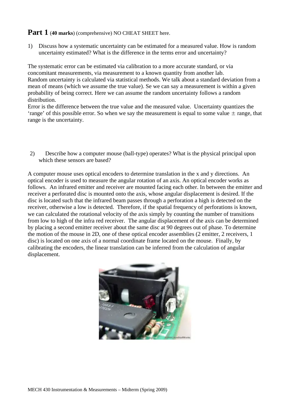
A computer mouse uses optical encoders to determine translation in the x and y directions. An
optical encoder is used to measure the angular rotation of an axis. An optical encoder works as
follows. An infrared emitter and receiver are mounted facing each other. In between the emitter and
receiver a perforated disc is mounted onto the axis, whose angular displacement is desired. If the
disc is located such that the infrared beam passes through a perforation a high is detected on the
receiver, otherwise a low is detected. Therefore, if the spatial frequency of perforations is known,
we can calculated the rotational velocity of the axis simply by counting the number of transitions
from low to high of the infra red receiver. The angular displacement of the axis can be determined
by placing a second emitter receiver about the same disc at 90 degrees out of phase. To determine
the motion of the mouse in 2D, one of these optical encoder assemblies (2 emitter, 2 receivers, 1
disc) is located on one axis of a normal coordinate frame located on the mouse. Finally, by
calibrating the encoders, the linear translation can be inferred from the calculation of angular
displacement.
MECH 430 Instrumentation & Measurements – Midterm (Spring 2009)
3) Describe with the aid of sketch what is the Hall-effect. What sensors did you see in your notes
that use this effect?
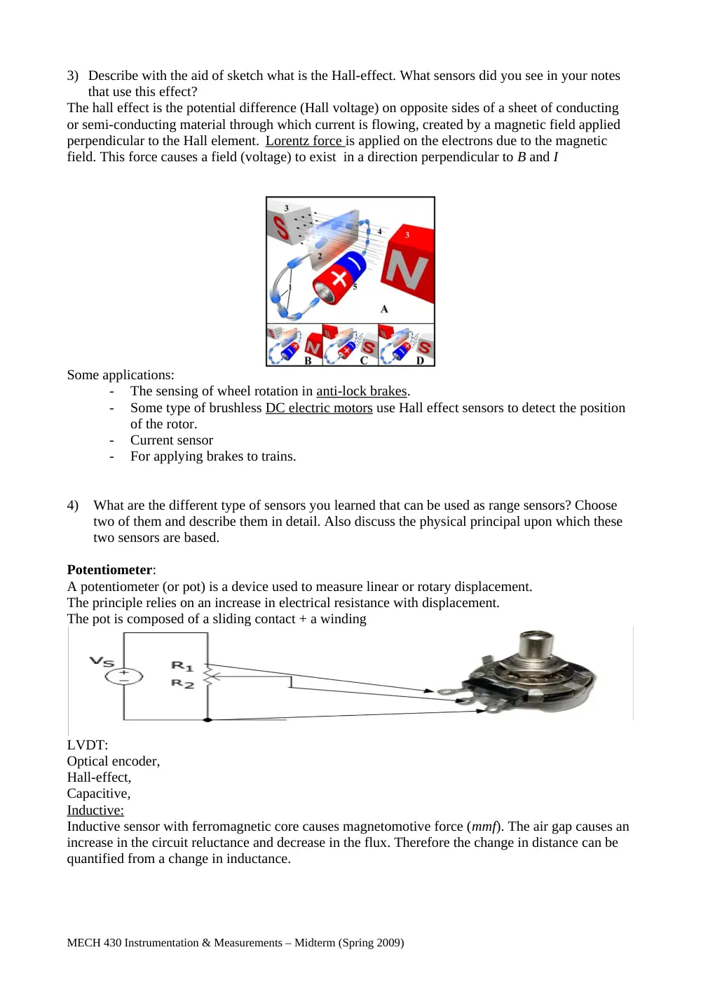
The hall effect is the potential difference (Hall voltage) on opposite sides of a sheet of conducting
or semi-conducting material through which current is flowing, created by a magnetic field applied
perpendicular to the Hall element. Lorentz force is applied on the electrons due to the magnetic
field. This force causes a field (voltage) to exist in a direction perpendicular to B and I
Some applications:
-
The sensing of wheel rotation in anti-lock brakes.
-
Some type of brushless DC electric motors use Hall effect sensors to detect the position
of the rotor.
-
Current sensor
-
For applying brakes to trains.
4)
What are the different type of sensors you learned that can be used as range sensors? Choose
two of them and describe them in detail. Also discuss the physical principal upon which these
two sensors are based.
Potentiometer:
A potentiometer (or pot) is a device used to measure linear or rotary displacement.
The principle relies on an increase in electrical resistance with displacement.
The pot is composed of a sliding contact + a winding
LVDT:
Optical encoder,
Hall-effect,
Capacitive,
Inductive:
Inductive sensor with ferromagnetic core causes magnetomotive force (mmf). The air gap causes an
increase in the circuit reluctance and decrease in the flux. Therefore the change in distance can be
quantified from a change in inductance.
MECH 430 Instrumentation & Measurements – Midterm (Spring 2009)
Eddy current,
Magnetoresistive,
Ultrasonic
5) Present four examples of pressure sensors. Explain 2 of them in detail and explain the physical
principle upon which they are based?
- U-tube,
A U tube (liquid column manometer) compares the pressure to be measured with a reference
pressure and yields a difference h of liquid level.
g
p
p
h
ref
- Bourdon tube,
- Diaphragm,
A diaphragm is a flexible circular plate consisting of a taut membrane that strains under the action
of a pressure difference. A micromachined diaphragm is an etched silicon wafer with implanted
gages that sense local strain.
- Capsule,
- Bellows,
- Piezoresistive,
- Capacitive,
- Moiré interferometry.
MECH 430 Instrumentation & Measurements – Midterm (Spring 2009)
6) Explain what is a load cell and what it is used for.
A load cell is an electronic device that transforms force into an electrical signal. The most common
load cells are based on strain gages. Other types of load cells include hydraulic load cells (increase
in pressure), or piezoelectric load cells (generates a voltage).
7)
What is the difference between a thermocouple and a thermistor? Explain each of them and
draw them.
•Thermocouples are used to measure the temperature gradient between two points. The sensor is
based on the principal that any conductor subjected to a temperature gradient, generates a voltage
(thermoelectric effect). Thermocouples connected in series are called thermopile.
Thermistor comes from `thermally sensitive resistor’ and applies to temperature-dependent resistors
that are based on ceramics or polymers and not on pure metals (as is the case for RTD’s). RTD are
useful over a high temperature range, while thermistors are more precise but work on a limited
temperature range. They are designated as NTC when having a negative temperature coefficient
and PTC when having a positive temperature coefficient.
MECH 430 Instrumentation & Measurements – Midterm (Spring 2009)
8)
What is a Pitot tube used for? Present its relevant equation.
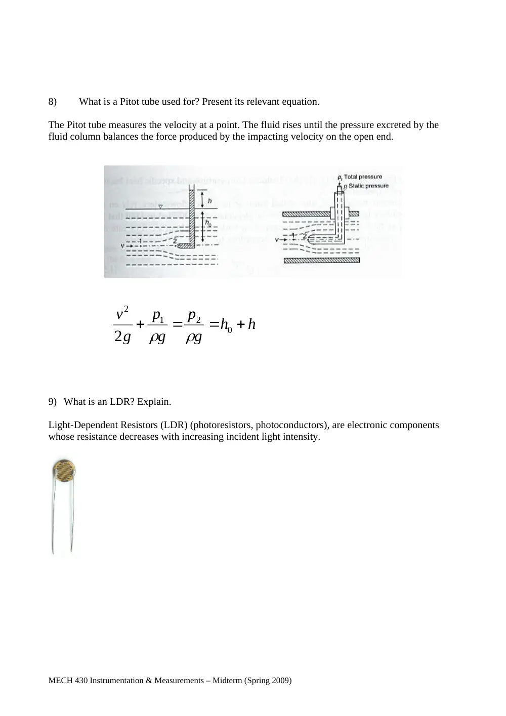
The Pitot tube measures the velocity at a point. The fluid rises until the pressure excreted by the
fluid column balances the force produced by the impacting velocity on the open end.
9) What is an LDR? Explain.
Light-Dependent Resistors (LDR) (photoresistors, photoconductors), are electronic components
whose resistance decreases with increasing incident light intensity.
MECH 430 Instrumentation & Measurements – Midterm (Spring 2009)
h
h
g
p
g
p
g
v
0
2
1
2
2
10)
With the aid of graphs describe what are sensitivity, drift, gain, FSO, FS, precision, accuracy,
threshold, and resolution? What is meant by an 8bit resolution?
Sensitivity or scale factor is slope of the static calibration curve.
Full-Scale input (FS) specifies the range of values that the sensor can convert. Full-Scale Output
(FSO) is the range of values that can be measured with the instrument.
MECH 430 Instrumentation & Measurements – Midterm (Spring 2009)
FS = xm ax −xm in
FSO = ym ax −ym in
11)
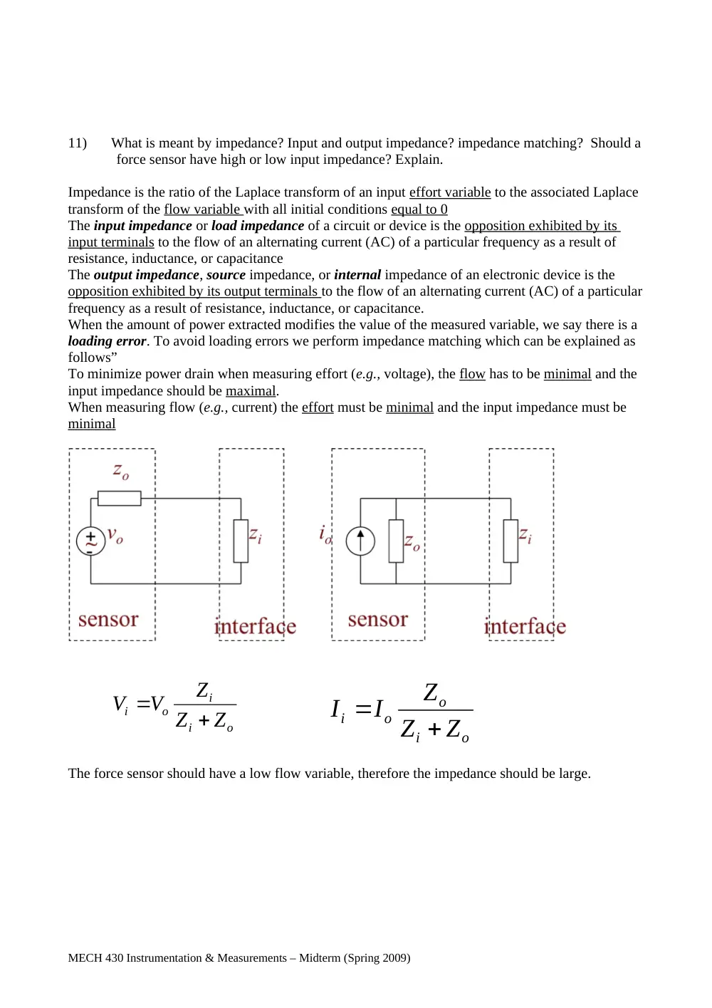
What is meant by impedance? Input and output impedance? impedance matching? Should a
force sensor have high or low input impedance? Explain.
Impedance is the ratio of the Laplace transform of an input effort variable to the associated Laplace
transform of the flow variable with all initial conditions equal to 0
The input impedance or load impedance of a circuit or device is the opposition exhibited by its
input terminals to the flow of an alternating current (AC) of a particular frequency as a result of
resistance, inductance, or capacitance
The output impedance, source impedance, or internal impedance of an electronic device is the
opposition exhibited by its output terminals to the flow of an alternating current (AC) of a particular
frequency as a result of resistance, inductance, or capacitance.
When the amount of power extracted modifies the value of the measured variable, we say there is a
loading error. To avoid loading errors we perform impedance matching which can be explained as
follows”
To minimize power drain when measuring effort (e.g., voltage), the flow has to be minimal and the
input impedance should be maximal.
When measuring flow (e.g., current) the effort must be minimal and the input impedance must be
minimal
o
i
i
o
i
Z
Z
Z
V
V
o
i
o
o
i
Z
Z
Z
I
I
The force sensor should have a low flow variable, therefore the impedance should be large.
MECH 430 Instrumentation & Measurements – Midterm (Spring 2009)
12)
Explain one of the DC problems of an op-amp and how do we remedy it.
Since op amps are direct-coupled devices with large gains at dc they are prone to dc problems.
The first problem is known as dc offset voltage.
In reality a finite dc voltage always exists at the output of the op-amp simply because of
unavoidable mismatches present in the input differential stage inside the op-amp.
The op-amp output can be brought back to its ideal value of 0V by connecting a dc voltage source
of appropriate polarity and magnitude between two input terminals of the op-amp.
The output due to this offset voltage can be considerably amplified.
dc offset voltage can be overcome by capacitively coupling the amplifier.
This is only possible when the signal to be amplified is not low frequency or dc (remember that a
capacitor impedes dc current)
MECH 430 Instrumentation & Measurements – Midterm (Spring 2009)
os
os
os
o
V
V
Cjw
R
R
V
Z
Z
V
1
1
1
1
2
1
2
1
2
1
R
R
V
V
os
o
Part II – Solving (60%) You may use a cheat sheet here.
Problem 1 (20 marks)
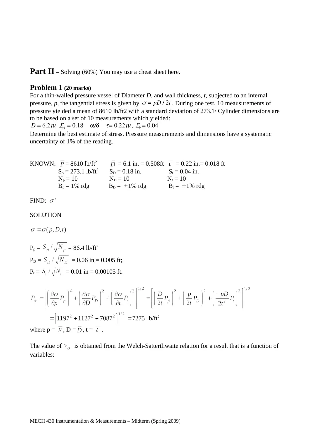
For a thin-walled pressure vessel of Diameter D, and wall thickness, t, subjected to an internal
pressure, p, the tangential stress is given by σ = pD / 2t . During one test, 10 meausurements of
pressure yielded a mean of 8610 lb/ft2 with a standard deviation of 273.1/ Cylinder dimensions are
to be based on a set of 10 measurements which yielded:
D = 6.2in, SD = 0.18 and t= 0.22in., St = 0.04
Determine the best estimate of stress. Pressure measurements and dimensions have a systematic
uncertainty of 1% of the reading.
KNOWN:
= 8610 lb/ft2
= 6.1 in. = 0.508ft
= 0.22 in.= 0.018 ft
Sp = 273.1 lb/ft2 SD = 0.18 in.
St = 0.04 in.
Np = 10 ND = 10 Nt = 10
Bp = 1% rdg
BD =
1% rdg Bt =
1% rdg
FIND:
SOLUTION
Pp =
= 86.4 lb/ft2
PD =
= 0.06 in = 0.005 ft;
Pt =
= 0.01 in = 0.00105 ft.
lb/ft2
where p =
, D =
, t =
.
The value of
is obtained from the Welch-Satterthwaite relation for a result that is a function of
variables:
MECH 430 Instrumentation & Measurements – Midterm (Spring 2009)
=
= 10
With Bp = 0.01 x 8610 = 86.1 lb/ft2 ,
BD = 0.01 x 6.1 = 0.061 in = 0.005 ft ,
Bt = 0.01 x 0.22 = 0.0022 in = 0.0002 ft,
and p =
, D =
, t =
lb/ft2
Then, with t10,95 = 2.228 and
lb/ft2 (95%)
MPa (95%)
Problem 2 (20 marks)
The area of a flat, rectangular parcel of land is computed from the measurement of the length of two
adjacent sides, X and Y. Measurements are made using a scaled chain accurate to within 0.5% over
its indicated length. The two sides are measured several times with the following results:
X = 556m Y = 222m
Sx = 5.3m Sy = 2.1m
ν = 8 ν = 7
Estimate the area of the land and state the confidence interval of that measurement at 95%.
KNOWN: A = XY
X and Y Instrument Accuracy: within 0.5% reading
FIND: Estimate the uncertainty in land area
SOLUTION
The land area is found by A = XY. Then, the most probable estimate of the mean area is:
A = XY = 556 x 222 = 123,432 m2
MECH 430 Instrumentation & Measurements – Midterm (Spring 2009)
In the measurement of length X (note: the subscripts refer to the order in which the particular errors
are listed in Table 5.2 – otherwise, they offer no special meaning):
Bx = B2 = 0.005 x 556 = 2.8 m
Px = P9 = Sx/N1/2 = 1.9 m
In the measurement of length Y:
By = B2 = 0.005 x 222 = 1.1 m
Py = P9 = Sx/N1/2 = 0.8 m
The propagation of these errors to the resultant area is found by
= 873 m2
= 606 m2
The degrees of freedom in PA is found using a Welch-Sattertwaite relation
=
Then, with t14,95 = 2.145,
= 123,432
1500 m2 (95%)
COMMENT
This uncertainty is about 1.75% of the measured area. The contribution from the instrument itself is
barely 0.7% of area. If we assume that the measurand does not change during measurement (so
barring seismic activity somewhat safely), the rest is due to lack of control in procedure.
MECH 430 Instrumentation & Measurements – Midterm (Spring 2009)
Problem 3 (20 marks)
The circuit shown below is called a Wien oscillator. It is used to generate sine waves by varying
the values of the resistors and capacitors.
Given:
For such a circuit to operate as an oscillator we analyze its feedback circuit (Figure 3) and have to
meet the following conditions:
The gain in this circuit must be 1V/V,
The phase shift should be 0 degrees.
In such designs it is customary to take C1 = C2 = C and R1 = R2 = R.
Find:
Determine the value of the potentiometer Rp in function of Rf for the circuit to operate as an
oscillator
Figure 1 Wien oscillator
Figure 2 Feedback circuit
MECH 430 Instrumentation & Measurements – Midterm (Spring 2009)
Solution:
Start by finding V1/Vin (V1 is the input of op-amp)
Using a voltage divider:
V1
Vin
=
Z1
Z1 + Z2
=
R1 || 1
C1s
R2 + 1
C2s+ R1 || 1
C1s
=
R1
1+ R1C1s
R2C2s+1
C2s
+
R1
1+ R1C1s
V1
Vin
=
R1C2s
(R2C2s+1
) 1+ R1C1s
(
) + R1C2s
V1
Vin
=
R1C2s
R2C2R1C1s2 + R1C1 + R2C2 + R1C2
(
)s+1
Sub in jw to get:
V1
Vin
=
R1C2 jw
1−R2C2R1C1w2 + R1C1 + R2C2 + R1C2
(
) jw
Phase angle condition:
1−R2C2R1C1w2 = 0
w2 =
1
R2C2R1C1
w = 1
RC
With this frequency the gain becomes:
V1
Vin
=
R1C2
(R1C1 + R2C2 + R1C2
)
= 1
3
We still need to introduce the gain of the non-inverting amplifier:
Gain angle condition (Gain = 1) we can find the value of K = 3 and
(1+ RF
RP
) = 3 ⇒ RP = RF
2
MECH 430 Instrumentation & Measurements – Midterm (Spring 2009)
MECH 430 Instrumentation & Measurements – Midterm (Spring 2009)
MECH 430 Instrumentation & Measurements – Midterm (Spring 2009)