
MECH 430 Project Pumping Station, Spring 2017
American University of Beirut · Instrumentation and Measurements · 329 pages



Showing the first 10 of 329 pages. Download the PDF to see all of it.
More MECH 430 files
Show the text of this project
2
0.918
3
1.17
4
1.52
5
1.87
6.5
2.28
7
2.43
8
2.64
9
2.77
10
3.1
11
3.23
12
3.49
13
3.65
14
3.78
15
3.96
16
4.03
17
4.138
18
4.36
0
2
4
6
8
10
12
0
1
2
3
4
5
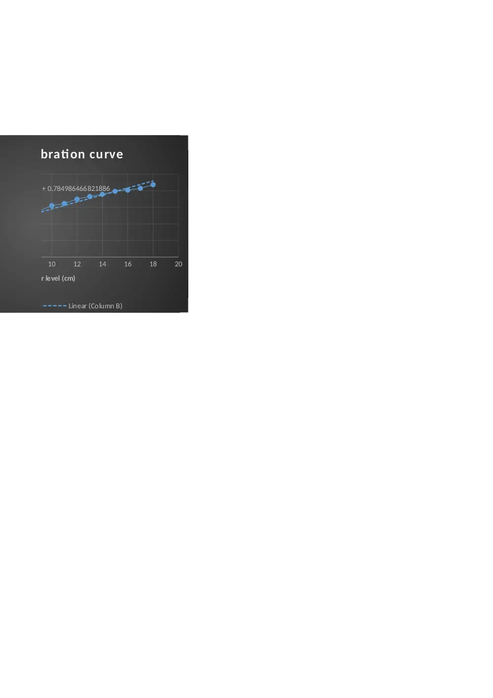
f(x) = 0.211092258440047 x + 0.78498646682
capacitor callibration c
Column B
Linear (C
water level (cm)
tau
6
8
10
12
14
16
18
20
2258440047 x + 0.784986466821886
or callibration curve
olumn B
Linear (Column B)
water level (cm)
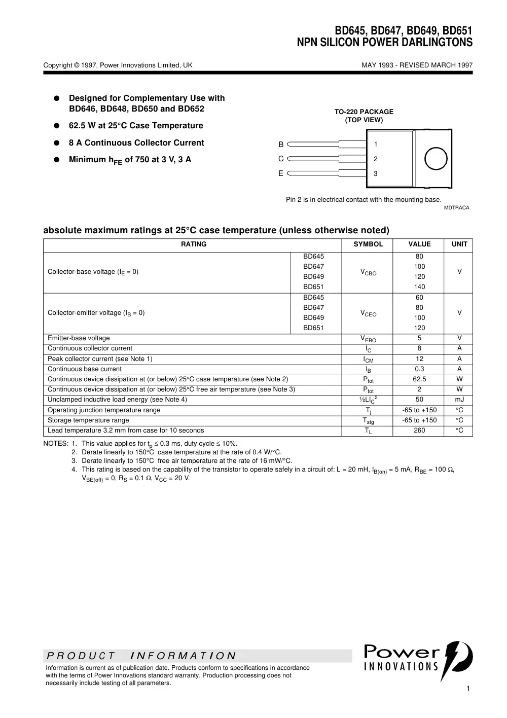
BD645, BD647, BD649, BD651
NPN SILICON POWER DARLINGTONS
P R O D U C T I N F O R M A T I O N
1
MAY 1993 - REVISED MARCH 1997
Copyright © 1997, Power Innovations Limited, UK
Information is current as of publication date. Products conform to specifications in accordance
with the terms of Power Innovations standard warranty. Production processing does not
necessarily include testing of all parameters.
G
Designed for Complementary Use with
BD646, BD648, BD650 and BD652
G
62.5 W at 25°C Case Temperature
G
8 A Continuous Collector Current
G
Minimum hFE of 750 at 3 V, 3 A
B
C
E
TO-220 PACKAGE
(TOP VIEW)
Pin 2 is in electrical contact with the mounting base.
MDTRACA
1
2
3
absolute maximum ratings at 25°C case temperature (unless otherwise noted)
NOTES: 1. This value applies for tp ≤ 0.3 ms, duty cycle ≤ 10%.
2. Derate linearly to 150°C case temperature at the rate of 0.4 W/°C.
3. Derate linearly to 150°C free air temperature at the rate of 16 mW/°C.
4. This rating is based on the capability of the transistor to operate safely in a circuit of: L = 20 mH, IB(on) = 5 mA, RBE = 100 Ω,
VBE(off) = 0, RS = 0.1 Ω, VCC = 20 V.
RATING
SYMBOL
VALUE
UNIT
Collector-base voltage (IE = 0)
BD645
BD647
BD649
BD651
VCBO
80
100
120
140
V
Collector-emitter voltage (IB = 0)
BD645
BD647
BD649
BD651
VCEO
60
80
100
120
V
Emitter-base voltage
VEBO
5
V
Continuous collector current
IC
8
A
Peak collector current (see Note 1)
ICM
12
A
Continuous base current
IB
0.3
A
Continuous device dissipation at (or below) 25°C case temperature (see Note 2)
Ptot
62.5
W
Continuous device dissipation at (or below) 25°C free air temperature (see Note 3)
Ptot
2
W
Unclamped inductive load energy (see Note 4)
½LIC
2
50
mJ
Operating junction temperature range
Tj
-65 to +150
°C
Storage temperature range
Tstg
-65 to +150
°C
Lead temperature 3.2 mm from case for 10 seconds
TL
260
°C
BD645, BD647, BD649, BD651
NPN SILICON POWER DARLINGTONS
2
MAY 1993 - REVISED MARCH 1997
P R O D U C T I N F O R M A T I O N
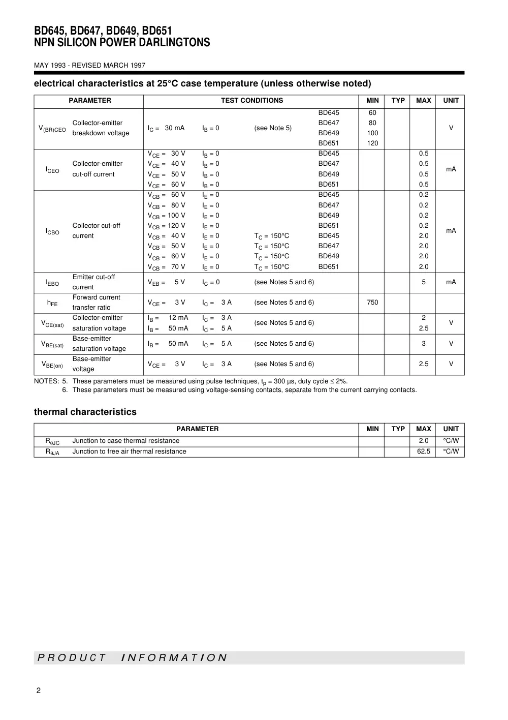
NOTES: 5. These parameters must be measured using pulse techniques, tp = 300 µs, duty cycle ≤ 2%.
6. These parameters must be measured using voltage-sensing contacts, separate from the current carrying contacts.
electrical characteristics at 25°C case temperature (unless otherwise noted)
PARAMETER
TEST CONDITIONS
MIN
TYP
MAX
UNIT
V(BR)CEO
Collector-emitter
breakdown voltage
IC = 30 mA
IB = 0
(see Note 5)
BD645
BD647
BD649
BD651
60
80
100
120
V
ICEO
Collector-emitter
cut-off current
VCE = 30 V
VCE = 40 V
VCE = 50 V
VCE = 60 V
IB = 0
IB = 0
IB = 0
IB = 0
BD645
BD647
BD649
BD651
0.5
0.5
0.5
0.5
mA
ICBO
Collector cut-off
current
VCB = 60 V
VCB = 80 V
VCB = 100 V
VCB = 120 V
VCB = 40 V
VCB = 50 V
VCB = 60 V
VCB = 70 V
IE = 0
IE = 0
IE = 0
IE = 0
IE = 0
IE = 0
IE = 0
IE = 0
TC = 150°C
TC = 150°C
TC = 150°C
TC = 150°C
BD645
BD647
BD649
BD651
BD645
BD647
BD649
BD651
0.2
0.2
0.2
0.2
2.0
2.0
2.0
2.0
mA
IEBO
Emitter cut-off
current
VEB = 5 V
IC = 0
(see Notes 5 and 6)
5
mA
hFE
Forward current
transfer ratio
VCE = 3 V
IC = 3 A
(see Notes 5 and 6)
750
VCE(sat)
Collector-emitter
saturation voltage
IB = 12 mA
IB = 50 mA
IC = 3 A
IC = 5 A
(see Notes 5 and 6)
2
2.5
V
VBE(sat)
Base-emitter
saturation voltage
IB = 50 mA
IC = 5 A
(see Notes 5 and 6)
3
V
VBE(on)
Base-emitter
voltage
VCE = 3 V
IC = 3 A
(see Notes 5 and 6)
2.5
V
thermal characteristics
PARAMETER
MIN
TYP
MAX
UNIT
RθJC
Junction to case thermal resistance
2.0
°C/W
RθJA
Junction to free air thermal resistance
62.5
°C/W
3
MAY 1993 - REVISED MARCH 1997
BD645, BD647, BD649, BD651
NPN SILICON POWER DARLINGTONS
P R O D U C T I N F O R M A T I O N
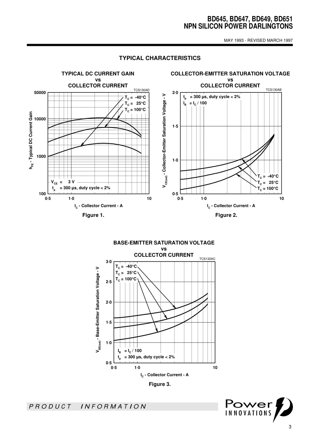
TYPICAL CHARACTERISTICS
Figure 1.
Figure 2.
Figure 3.
TYPICAL DC CURRENT GAIN
vs
COLLECTOR CURRENT
IC - Collector Current - A
0·5
1·0
10
hFE - Typical DC Current Gain
50000
100
1000
10000
TCS130AD
TC = -40°C
TC = 25°C
TC = 100°C
VCE = 3 V
tp = 300 µs, duty cycle < 2%
COLLECTOR-EMITTER SATURATION VOLTAGE
vs
COLLECTOR CURRENT
IC - Collector Current - A
0·5
1·0
10
VCE(sat) - Collector-Emitter Saturation Voltage - V
0·5
1·0
1·5
2·0
TCS130AB
TC = -40°C
TC = 25°C
TC = 100°C
tp = 300 µs, duty cycle < 2%
IB = IC / 100
BASE-EMITTER SATURATION VOLTAGE
vs
COLLECTOR CURRENT
IC - Collector Current - A
0·5
1·0
10
VBE(sat) - Base-Emitter Saturation Voltage - V
0·5
1·0
1·5
2·0
2·5
3·0
TCS130AC
TC = -40°C
TC = 25°C
TC = 100°C
IB = IC / 100
tp = 300 µs, duty cycle < 2%
BD645, BD647, BD649, BD651
NPN SILICON POWER DARLINGTONS
4
MAY 1993 - REVISED MARCH 1997
P R O D U C T I N F O R M A T I O N
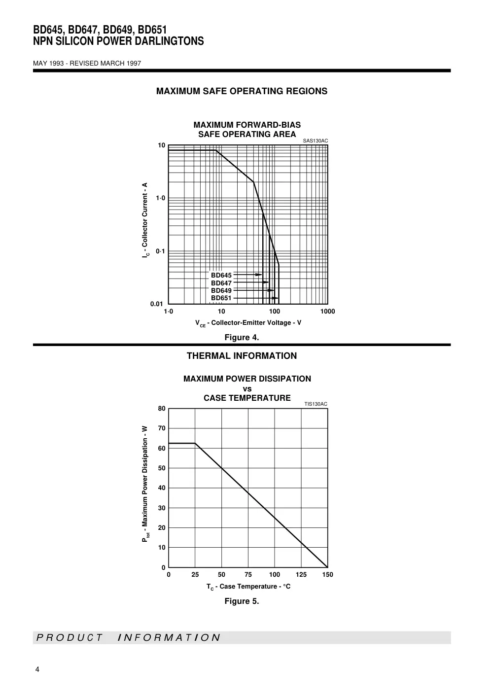
MAXIMUM SAFE OPERATING REGIONS
Figure 4.
THERMAL INFORMATION
Figure 5.
MAXIMUM FORWARD-BIAS
SAFE OPERATING AREA
VCE - Collector-Emitter Voltage - V
1·0
10
100
1000
IC - Collector Current - A
0.01
0·1
1·0
10
SAS130AC
BD645
BD647
BD649
BD651
MAXIMUM POWER DISSIPATION
vs
CASE TEMPERATURE
TC - Case Temperature - °C
0
25
50
75
100
125
150
Ptot - Maximum Power Dissipation - W
0
10
20
30
40
50
60
70
80
TIS130AC
5
MAY 1993 - REVISED MARCH 1997
BD645, BD647, BD649, BD651
NPN SILICON POWER DARLINGTONS
P R O D U C T I N F O R M A T I O N
TO-220
3-pin plastic flange-mount package
This single-in-line package consists of a circuit mounted on a lead frame and encapsulated within a plastic
compound. The compound will withstand soldering temperature with no deformation, and circuit performance
characteristics will remain stable when operated in high humidity conditions. Leads require no additional
cleaning or processing when used in soldered assembly.
MECHANICAL DATA
TO220
ALL LINEAR DIMENSIONS IN MILLIMETERS
ø
1,23
1,32
4,20
4,70
1
2
3
0,97
0,61
see Note C
see Note B
10,0
10,4
2,54
2,95
6,0
6,6
14,55
15,90
12,7
14,1
3,5
6,1
1,07
1,70
2,34
2,74
4,88
5,28
3,71
3,96
0,41
0,64
2,40
2,90
VERSION 2
VERSION 1
NOTES: A. The centre pin is in electrical contact with the mounting tab.
B. Mounting tab corner profile according to package version.
C. Typical fixing hole centre stand off height according to package version.
Version 1, 18.0 mm. Version 2, 17.6 mm.
MDXXBE
BD645, BD647, BD649, BD651
NPN SILICON POWER DARLINGTONS
6
MAY 1993 - REVISED MARCH 1997
P R O D U C T I N F O R M A T I O N
IMPORTANT NOTICE
Power Innovations Limited (PI) reserves the right to make changes to its products or to discontinue any
semiconductor product or service without notice, and advises its customers to verify, before placing orders, that the
information being relied on is current.
PI warrants performance of its semiconductor products to the specifications applicable at the time of sale in
accordance with PI's standard warranty. Testing and other quality control techniques are utilized to the extent PI
deems necessary to support this warranty. Specific testing of all parameters of each device is not necessarily
performed, except as mandated by government requirements.
PI accepts no liability for applications assistance, customer product design, software performance, or infringement
of patents or services described herein. Nor is any license, either express or implied, granted under any patent
right, copyright, design right, or other intellectual property right of PI covering or relating to any combination,
machine, or process in which such semiconductor products or services might be or are used.
PI SEMICONDUCTOR PRODUCTS ARE NOT DESIGNED, INTENDED, AUTHORIZED, OR WARRANTED TO BE
SUITABLE FOR USE IN LIFE-SUPPORT APPLICATIONS, DEVICES OR SYSTEMS.
Copyright © 1997, Power Innovations Limited
Chapter 2
Capacitive Sensing Technology
2.1 Overview
This chapter describes the basic properties of capacitive sensor technologies and their
use in various kinds of sensors in industrial applications. Physical properties as well as
somelimitationsofcapacitivesensingaredescribedhere.Theuseofcapacitivesensors
with hazardous fluids, such as gasoline based fuels, and various configurations of
capacitive sensors used in the application of fluid level measurement in dynamic
environments are described. In brief, this chapter provides information on capacitive
sensing technology and its use in dynamic and hostile environments.
2.2 Characteristics of Capacitors
2.2.1 Overview
Capacitors are the basic building blocks of the electronic world. To understand
how capacitive sensors operate, it is important to understand the fundamental
properties and principles of capacitors. This section provides details on the
underlying principles of the capacitor. The physical, geometrical, and the electrical
properties of capacitors are discussed in this section.
2.2.2 A Capacitor
A capacitor is a device that consists of two electrodes separated by an insulator [1].
Capacitors are generally composed of two conducting plates separated by a non-
E. Terzic et al., A Neural Network Approach to Fluid Quantity Measurement
in Dynamic Environments, DOI: 10.1007/978-1-4471-4060-3_2,
� Springer-Verlag London 2012
11
conducting substance called dielectric (er) [1, 2]. The dielectric may be air, mica,
ceramic, fuel, or other suitable insulating material [2]. The electrical energy or
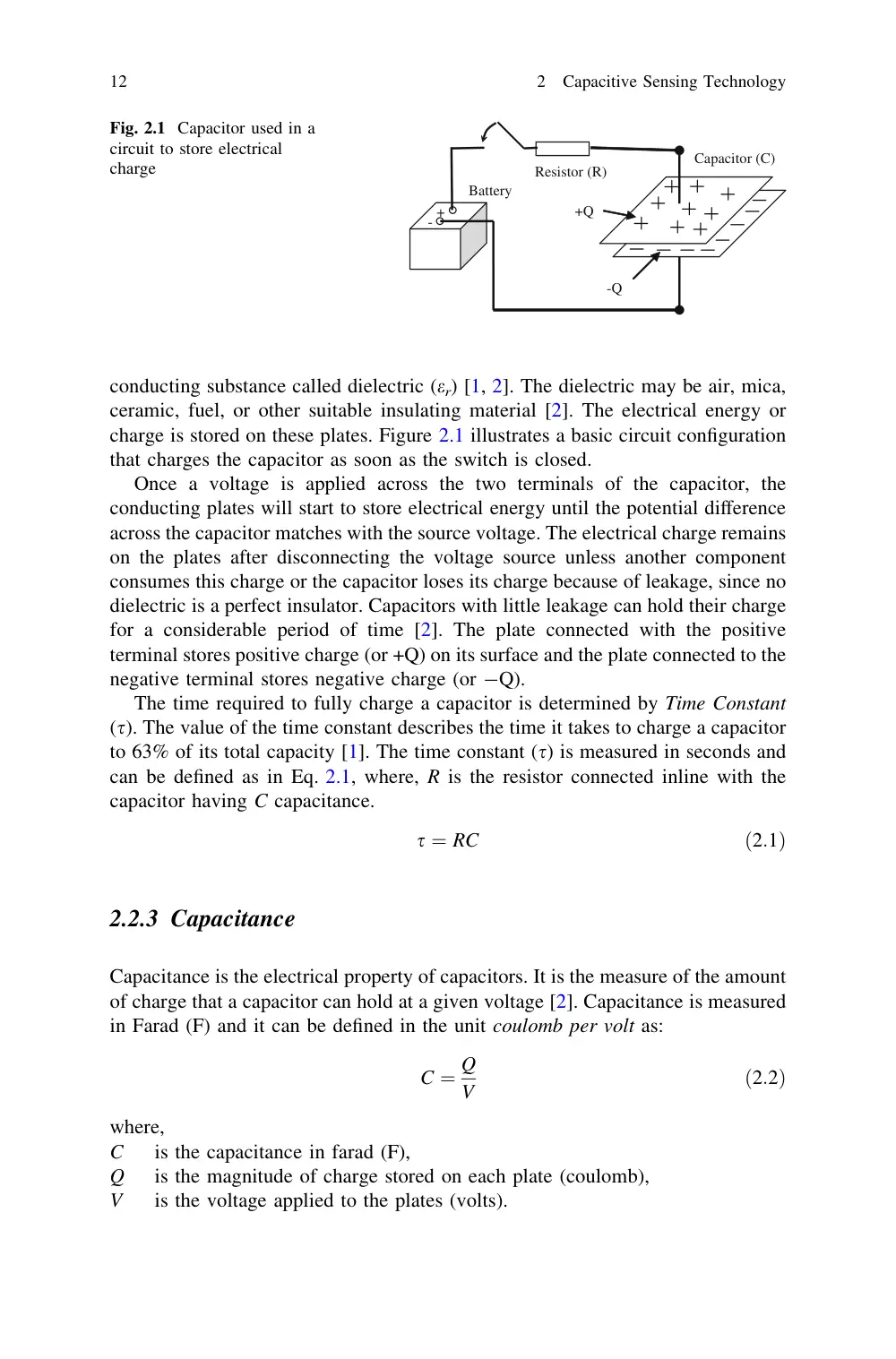
charge is stored on these plates. Figure 2.1 illustrates a basic circuit configuration
that charges the capacitor as soon as the switch is closed.
Once a voltage is applied across the two terminals of the capacitor, the
conducting plates will start to store electrical energy until the potential difference
across the capacitor matches with the source voltage. The electrical charge remains
on the plates after disconnecting the voltage source unless another component
consumes this charge or the capacitor loses its charge because of leakage, since no
dielectric is a perfect insulator. Capacitors with little leakage can hold their charge
for a considerable period of time [2]. The plate connected with the positive
terminal stores positive charge (or +Q) on its surface and the plate connected to the
negative terminal stores negative charge (or -Q).
The time required to fully charge a capacitor is determined by Time Constant
(s). The value of the time constant describes the time it takes to charge a capacitor
to 63% of its total capacity [1]. The time constant (s) is measured in seconds and
can be defined as in Eq. 2.1, where, R is the resistor connected inline with the
capacitor having C capacitance.
s ¼ RC
ð2:1Þ
2.2.3 Capacitance
Capacitance is the electrical property of capacitors. It is the measure of the amount
of charge that a capacitor can hold at a given voltage [2]. Capacitance is measured
in Farad (F) and it can be defined in the unit coulomb per volt as:
C ¼ Q
V
ð2:2Þ
where,
C
is the capacitance in farad (F),
Q
is the magnitude of charge stored on each plate (coulomb),
V
is the voltage applied to the plates (volts).
Battery
Capacitor (C)
+Q
-Q
+
-
Resistor (R)
Fig. 2.1 Capacitor used in a
circuit to store electrical
charge
12
2
Capacitive Sensing Technology
A capacitor with the capacitance of one farad can store one coulomb of charge
when the voltage across its terminals is 1 V [2]. Typical capacitance values range
from about 1 pF (10-12 F) to about 1,000 lF (10-3 F) [3]. An electric field will
exist between the two plates of a capacitor if the voltage is applied to one of the
plates [1]. The resulting electric field is due to the difference between the electric
charges stored on the surfaces of each plate. The capacitance describes the effects
on the electric field due to the space between the two plates.
The capacitance depends on the geometry of the conductors and not on an
external source of charge or potential difference [2, 4]. The space between the two
plates of the capacitor is covered with dielectric material. In general, the capaci-
tance value is determined by the dielectric material, distance between the plates,
and the area of each plate (illustrated in Fig. 2.2). The capacitance of a capacitor
can be expressed in terms of its geometry and dielectric constant as [5]:
C ¼ er
e0A
d
ð2:3Þ
where,
C
is the capacitance in farads (F),
er
is the relative static permittivity (dielectric constant) of the material between
the plates,
e0
is the permittivity of free space, which is equal to 8:854 � 10�12 F=m;
A
is the area of each plate, in square meters and
d
is the separation distance (in meters) of the two plates.
The capacitance phenomenon is related to the electric field between the two
plates of the capacitor [6]. The electric field strength between the two plates
decreases as the distance between the two conducting plates increases [1].
Lower field strength or greater separation distance will lower the capacitance
value. The conducting plates with larger surface area are able to store more
electrical charge; therefore, a larger capacitance value is obtained with greater
surface area.
A
d
(a)
A
d
(b)
A
d
(c)
Fig. 2.2 Factors influencing capacitance value. a Normal. b Increased surface area, increased
capacitance. c Decreased gap distance, increased capacitance
2.2
Characteristics of Capacitors
13
2.2.4 Capacitance in Parallel and Series Circuits
The net capacitance of two or more capacitors, connected next to each other,
depends on their connection configurations [3]. If two capacitors are connected in
parallel, they both will have the same voltage across them; therefore, their net
capacitance will be the sum of the two capacitances. The net capacitance of a
parallel combination of capacitors is given as [4]:
CT ¼ Q1
V þ Q2
V þ � � � þ Qn
V ; or
ð2:4Þ
CT ¼ C1 þ C2 þ � � � þ Cn
ð2:5Þ
where, CT is the total capacitance of the capacitors connected in parallel.
Figure 2.3 shows the circuit configuration of multiple capacitors having capaci-
tances (C1, C2,…, C4). Both circuits (a) and (b) have the equivalent capacitance CT,
which is the sum of all capacitances. However, if two or more capacitors are con-
nected in series, the voltage across the two terminals may be different for each
capacitor; although the electric charge will be the same on all of them [4]. The
equivalent capacitance of capacitors connected in series can be stated as (Fig. 2.4):
1
CT
¼ V1
Q þ V2
Q þ � � � þ Vn
Q ; or
ð2:6Þ
1
CT
¼ 1
C1
þ 1
C2
þ � � � þ 1
Cn
ð2:7Þ
V
C1
C2
C3
C4
V
CT
(a)
(b)
Fig. 2.3 Net capacitance of capacitors connected in parallel
(a)
V
C1
C2
C3
(b)
V
CT
Fig. 2.4 Net capacitance of capacitors connected in series
14
2
Capacitive Sensing Technology
2.2.5 Dielectric Constant
The gap between the two surfacesofa capacitor is filled with a non-conducting material
such as rubber, glass or, wood thatseparates the two electrodes of thecapacitor[4]. This
material has a certain dielectric constant. The dielectric constant is the measure of a
material’s influence on the electric field. The net capacitance will increase or decrease
dependingonthetype of dielectricmaterial.Permittivityrelatestoa material’sabilityto
transmit an electric field. In the capacitors, an increased permittivity allows the same
charge to be stored with a smaller electric field, leading to an increased capacitance.
According to Eq. 2.3, the capacitance is proportional to the amount of dielectric
constant. As the dielectric constant between the capacitive plates of a capacitor
rises, the capacitance will also increase accordingly. The capacitance can be stated
in terms of the dielectric constant, as [4]:
C ¼ er � C0
ð2:8Þ
where, C is the capacitance in Farads, er is the dielectric constant and C0 is the
capacitance in the absence of dielectric constant.
Different materials have different magnitudes of dielectric constant. For
example, air has a nominal dielectric constant equal to 1.0, and some common oils
or fluids such as gasoline have nominal dielectric constant of 2.2. If gasoline is
used as dielectric instead of air, the capacitance value using the gasoline as
dielectric will increase by a factor of 2.2. This factor is called Relative dielectric
constant or Relative electric permittivity [2]. Some commonly used dielectric
materials and their corresponding dielectric values are listed in Table 2.1.
2.2.6 Dielectric Strength
The electrical insulating properties of any material are dependent on dielectric
strength [7]. The dielectric strength of an insulating material describes the
Table 2.1 Commonly used dielectric materials and their values [4, 6]
Material
Dielectric constant
Material
Dielectric constant
Accetone
19.5
Mica
5.7–6.7
Air
1.0
Paper
1.6–2.6
Alcohol
25.8
Petroleum
2.0–2.2
Ammonia
15–25.0
Polystyene
3.0
Carbon dioxide
1.0
Powdered milk
3.5–4.0
Chlorine liquid
2.0
Salt
6.1
Ethanol
24.0
Sugar
3.3
Gasoline
2.2
Transformer oil
2.2
Glycerin
47.0
Turpentine oil
2.2
Hard paper
4.5
Water
80.0
2.2
Characteristics of Capacitors
15
maximum electric field of that material. If the magnitude of the electric field across
the dielectric material exceeds the value of the dielectric strength, the insulating
properties of the dielectric material will breakdown and the dielectric material will
begin to conduct [1]. The breakdown voltage or rated voltage of a capacitor
represents the largest voltage that can be applied to the capacitor without
exceeding the dielectric strength of the dielectric material [1]. The applied voltage
across a capacitor must be less than its rated voltage. The operating voltage across
a capacitor can be increased depending on the insulating material or the dielectric
constant. Teflon and Polyvinyl chloride have greater dielectric strength. The
dielectric constant can be increased by adding high dielectric constant filler
material [8]. Table 2.2 lists the dielectric strength values for different types of
materials at room temperature.
Factors such as thickness of the specimen, operating temperature, frequency,
and humidity can affect the strength of the dielectric materials.
2.3 Capacitive Sensor Applications
2.3.1 Overview
A capacitive sensor converts a change in position, or properties of the dielectric
material into an electrical signal [9]. According to the Eq. 2.3 in Sect. 2.2.3,
capacitive sensors are realized by varying any of the three parameters of a
capacitor: distance (d), area of capacitive plates (A), and dielectric constant (er);
therefore:
C ¼ fðd; A; erÞ
ð2:9Þ
A wide variety of different kinds of sensors have been developed that are
primarily based on the capacitive principle described in Eq. 2.3. These sensors’
functionalities
range
from
humidity
sensing,
through
level
sensing,
to
Table 2.2 Approximate dielectric strengths of various materials [4]
Material
Dielectric strength
(106 V/m)
Material
Dielectric strength
(106 V/m)
Air (dry)
3
Polystyrene
24
Bakelite
24
Polyvinyl chloride
40
Fused quartz
8
Porcelain
12
Mylar
7
Pyrex glass
14
Neoprene rubber
12
Silicone oil
15
Nylon
14
Strontium titanate
8
Paper
16
Teflon
60
Paraffin-impregnated paper
11
16
2
Capacitive Sensing Technology
displacement sensing [10]. A number of different kinds of capacitance based
sensors used in a variety of industrial and automotive applications are discussed in
this section.
2.3.2 Proximity Sensing
A proximity sensor is a transducer that is able to detect the presence of nearby
objects without any physical contact. Normally a proximity sensor emits an
electromagnetic or electrostatic field, or a beam of electromagnetic radiation (e.g.
infrared), and detects any change in the field or return signal. Capacitive type
proximity sensors consist of an oscillator whose frequency is determined by an
inductance–capacitance (LC) circuit to which a metal plate is connected. When a
conducting or partially conducting object comes near the plate, the mutual
capacitance changes the oscillator frequency. This change is detected and sent to
the controller unit [11]. The object being sensed is often referred to as the prox-
imity sensor’s target. Figure 2.5 shows an example of the capacitive proximity
sensor. As the distance between the proximity sensor and the target object gets
smaller, the electric field distributed around the capacitor experiences a change,
which is detected by the controller unit.
The maximum distance that a proximity sensor can detect is defined as
‘nominal range’. Some sensors have adjustments of the nominal range or ways to
report a graduated detection distance. A proximity sensor adjusted to a very short
range is often used as a touch switch. Capacitive proximity detectors have a range
twice that of inductive sensors, while they detect not only metal objects but also
dielectrics such as paper, glass, wood, and plastics [12]. They can even detect
through a wall or cardboard box [12]. Because the human body behaves as an
electric conductor at low frequencies, capacitive sensors have been used for human
tremor measurement and in intrusion alarms [12]. Capacitive type proximity
sensors have a high reliability and long functional life because of the absence of
mechanical parts and lack of physical contact between sensor and the sensed
object.
An example of a proximity sensor is a limit switch, which is a mechanical push-
button switch that is mounted in such a way that it is activated when a mechanical
part or lever arm gets to the end of its intended travel [13]. It can be implemented
Capacitive
Proximity Sensor
Target
Object
Electric Field
Fig. 2.5 Capacitance based
proximity sensor
2.3
Capacitive Sensor Applications
17
in an automatic garage door opener; where the controller needs to know if the door
is all the way open or all the way closed [13]. Other applications of the capacitive
proximity sensors are:
• Spacing—If a metal object is near a capacitor electrode, the mutual capacitance
is a very sensitive measure of spacing [14].
• Thickness measurement—Two plates in contact with an insulator will measure
the insulator thickness if its dielectric constant is known, or the dielectric
constant if the thickness is known [14].
• Pressure sensing—A diaphragm with stable deflection properties can measure
pressure with a spacing-sensitive detector [14].
2.3.3 Position Sensing
A position sensor is a device that allows position measurement. Position can be either an
absolutepositionorarelativeone[15].Linearaswellasangularpositioncanbemeasured
using position sensors. Position sensors are used in many industrial applications such
as fluid level measurement, shaft angle measurement, gear position sensing, digital
encoders and counters, and touch screen coordinate systems. Traditionally, resistive type
potentiometers were used to determine rotary and linear position. However, the limited
functional life of these sensors caused by mechanical wear has made resistive sensors
less attractive for industrial applications. Capacitive type position sensors are normally
non-mechanical devices that determine the position based on the physical parameters of
the capacitor. Position measurement using a capacitive position sensor can be performed
by varying the three capacitive parameters: Area of the capacitive plate, Dielectric
constant,and Distance betweenthe plates.The following applicationsare some examples
of the utilization of capacitive position sensors in:
• Liquid level sensing—Capacitive liquid level detectors sense the liquid level in a
reservoir by measuring changes in capacitance between conducting plates which
are immersed in the liquid, or applied to the outside of a non-conducting tank
[14].
• Shaft angle or linear position—Capacitive sensors can measure angle or position
with a multi-plate scheme giving high accuracy and digital output, or with an
analogue output with less absolute accuracy but faster response and simpler
circuitry.
• X–Y tablet—Capacitive graphic input tablets of different sizes can replace the
computer mouse as an x–y coordinate input device. Finger-touch-sensitive
devices such as iPhone [16], z-axis-sensitive and stylus-activated devices are
available.
• Flow meter—Many types offlow meters convert flow to pressure or displacement,
using an orifice for volume flow or Coriolis Effect force for mass flow. Capacitive
sensors can then measure the displacement.
18
2
Capacitive Sensing Technology
2.3.4 Humidity Sensing
The dielectric constant of air is affected by humidity. As humidity increases the
dielectric increases [17]. The permittivities of atmospheric air, of some gases, and
of many solid materials are functions of moisture content and temperature [10].
Capacitive humidity devices are based on the changes in the permittivity of the
dielectric material between plates of capacitors [10]. Capacitive humidity sensors
commonly contain layers of hydrophilic inorganic oxides which act as a dielectric
[18]. Absorption of polar water molecules has a strong effect on the dielectric
constant of the material [18]. The magnitude of this effect increases with a large
inner surface which can accept large amounts of water [18].
The ability of the capacitive humidity sensors to function accurately and reliably
extends over a wide range of temperatures and pressures. They also exhibit low
hysteresis and high stability with minimal maintenance requirements. These features
make capacitive humidity sensors viable for many specific operating conditions and
ideally suitable for a system where uncertainty of unaccounted conditions exists
during operations. There are many types of capacitive humidity sensors, which are
mainly formed with aluminium, tantalum, silicon, and polymer types [10].
2.3.5 Tilt Sensing
In recent years, capacitive-type micro-machined accelerometers are gaining popularity.
These accelerometers use the proof mass as one plate of the capacitor and use the other
plate as thebase.Whenthesensor is accelerated, theproofmass tendsto move; thus, the
voltage across the capacitor changes. This change in voltage corresponds to the applied
acceleration. Micromachined accelerometers have found their way into automotive
airbags, automotive suspension systems, stabilization systems for video equipment,
transportation shock recorders, and activity responsive pacemakers [19].
Capacitive silicon accelerometers are available in a wide range of specifications.
A typical lightweight sensor will have a frequency range of 0–1,000 Hz, and a
dynamic range of acceleration of ±2 to ±500 g [19]. Analogue Devices, Inc. [20] has
introduced integrated accelerometer circuits with a sensitivity of over 1.5 g [14].
With this sensitivity, the device can be used as a tiltmeter [14].
2.4 Capacitors in Level Sensing
2.4.1 Overview
The general properties of the capacitor described in Sect. 2.2.3 can be used to
measure the fluid level in a storage tank. In a basic capacitive level sensing system,
capacitive sensors have two conducting terminals that establish a capacitor. If the
2.3
Capacitive Sensor Applications
19
gap between the two rods is fixed, the fluid level can be determined by measuring
the capacitance between the conductors immersed in the liquid. Since the capac-
itance is proportional to the dielectric constant, fluids rising between the two
parallel rods will increase the net capacitance of the measuring cell as a function of
fluid height. To measure the liquid level, an excitation voltage is applied with a
drive electrode and detected with a sense electrode. Figure 2.6 illustrates a basic
set-up of a liquid level measurement system.
In this section, various aspects and configurations of capacitive fluid level
measurement systems have been described in detail.
2.4.2 Sensing Electrodes
The sensing electrodes of the capacitive sensor could be shaped into various forms
and structures. The geometry of the sensing electrodes influences the electric field
between them. For example, the capacitance between two parallel rods will be
different from that between two parallel plates because of the nature of electric
field distribution around an electrically charged object. A few types of sensing
electrodes, such as cylindrical rods, rectangular plates, helixical wires, and tubular
shaped capacitors are described in this subsection.
2.4.2.1 Cylindrical Rods
Cylindrical rods are made of conductors, where the negative electrode stores the
negative charge and the positive electrode stores the positive charge. An electrical
field will exist between the two electrodes if a voltage is applied across them.
Figure 2.7 illustrates the two cylindrical rods separated by distance d. The capac-
itance between the two parallel rods can be determined by the following rule [21]:
C ¼ pe0er
ln d
r
L;
If d � r
ð2:9Þ
Drive
electrode
Sense
electrode
Fluid
Fig. 2.6 Basic liquid level
sensing system
20
2
Capacitive Sensing Technology
C ¼
pe0er
ln d þ
ffiffiffiffiffiffiffiffiffiffiffiffiffiffiffiffiffi
d2 � 4r2
p
2r
! L;
where d � r
ð2:10Þ
where,
C
is the capacitance in farads (F),
er
is the relative static permittivity (dielectric constant) of the material between
the plates,
e0
is the permittivity of free space, which is equal to 8:854 � 10�12 F=m;
L
is the rod length in meters,
d
is the separation distance (in meters) of the two rods,
r
is the radius of the rod in meters.
2.4.2.2 Cylindrical Tubes
Cylindrical tube based electrodes are commonly used in tubular capacitive sensors.
Tubular capacitive sensors have a simple design, which makes them easier to
manufacture. Maier [22] has used capacitive sensors that are formed as concentric,
elongated cylinders for sensing the fuel level in aircraft fuel tanks. The capacitance
of the sensor varies as a function of the fraction of the sensor wetted by the fuel
and the un-wetted fraction in the airspace above the fuel/air interface [22].
Figure 2.8 shows an illustration of the cylindrical tube capacitor. A cylindrical
capacitor can be thought of as having two cylindrical tubes, inner and outer. The
inner cylinder can be connected to the positive terminal, whereas the outer cylinder
can be connected to the negative terminal. An electric field will exist if a voltage is
applied across the two terminals. If ra is the radius of the inner cylinder and rb is
the radius of the o