
MECH 430 Notes 7, Spring 2014
American University of Beirut · Instrumentation and Measurements · 32 pages



Showing the first 10 of 32 pages. Download the PDF to see all of it.
More MECH 430 files
Show the text of this notes
- +
Instrumentation & Measurements
MECH 430
MECH 430
Slide 1
Chapter 7
Sampling, Digital
Devices, and Data
Acquisition
- +
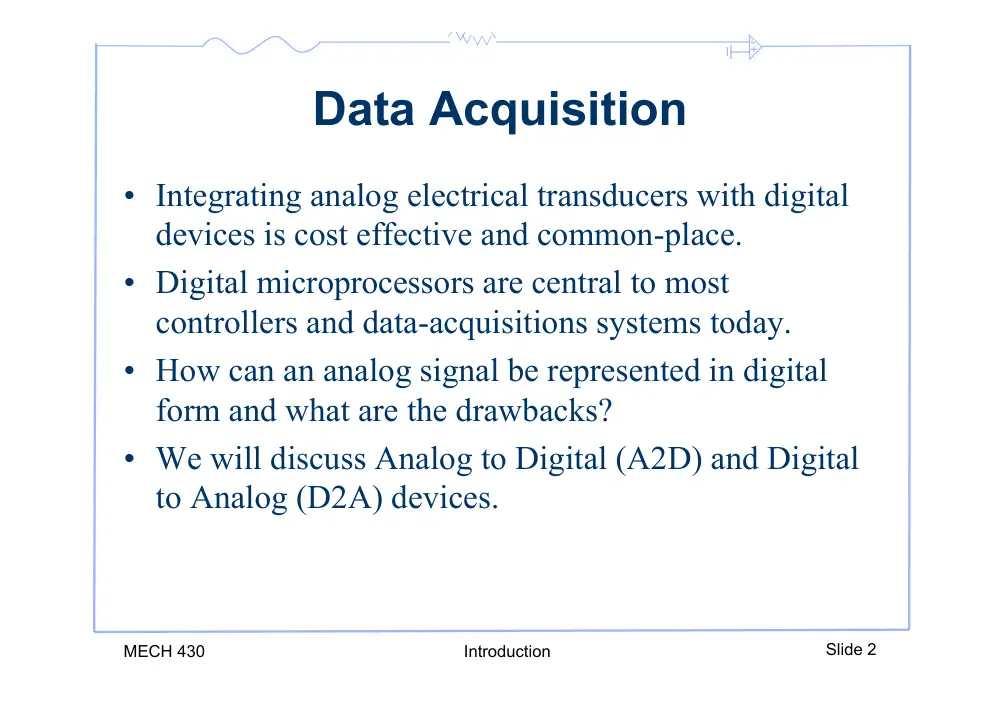
Data Acquisition
• Integrating analog electrical transducers with digital
devices is cost effective and common-place.
• Digital microprocessors are central to most
controllers and data-acquisitions systems today.
• How can an analog signal be represented in digital
form and what are the drawbacks?
• We will discuss Analog to Digital (A2D) and Digital
to Analog (D2A) devices.
MECH 430
Introduction
Slide 2
- +
MECH 430
SC_A/D conversion
Slide 3
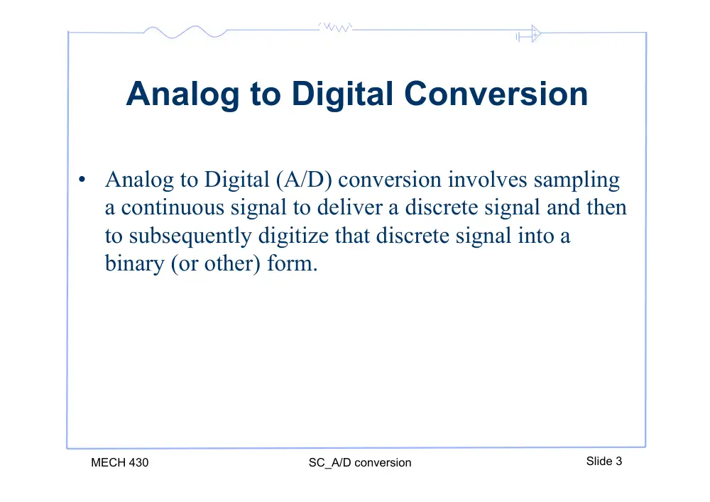
Analog to Digital Conversion
• Analog to Digital (A/D) conversion involves sampling
a continuous signal to deliver a discrete signal and then
to subsequently digitize that discrete signal into a
binary (or other) form.
- +
MECH 430
SC_A/D conversion
Slide 4
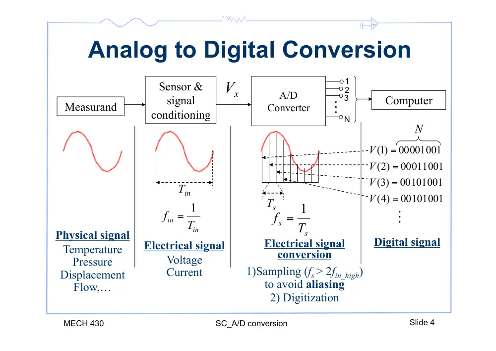
Analog to Digital Conversion
Measurand
Sensor &
signal
conditioning
Physical signal
Temperature
Pressure
Displacement
Flow,…
Electrical signal
Voltage
Current
Electrical signal
conversion
1)Sampling (fs > 2fin_high)
to avoid aliasing
2) Digitization
Tin
in
in
T
f
1
=
s
s
T
f
1
=
Ts
A/D
Converter
x
V
1
2
3
N
Computer
Digital signal
00101001
4)
(
00101001
3)
(
00011001
2)
(
00001001
)1(
=
=
=
=
V
V
V
V
N
- +
MECH 430
SC_A/D conversion
Slide 5
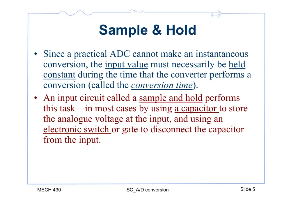
Sample & Hold
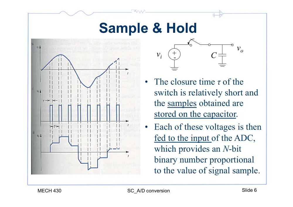
• Since a practical ADC cannot make an instantaneous
conversion, the input value must necessarily be held
constant during the time that the converter performs a
conversion (called the conversion time).
• An input circuit called a sample and hold performs
this task—in most cases by using a capacitor to store
the analogue voltage at the input, and using an
electronic switch or gate to disconnect the capacitor
from the input.
- +
MECH 430
SC_A/D conversion
Slide 6
Sample & Hold
+ -
vi
vo
C
• The closure time τ of the
switch is relatively short and
the samples obtained are
stored on the capacitor.
• Each of these voltages is then
fed to the input of the ADC,
which provides an N-bit
binary number proportional
to the value of signal sample.
- +
Analog to Digital Conversion
• The output of an A/D converter depends on :
– Low and high reference voltages VRL and VRH (If VRL and VRH
have the same polarity, the A/D is a unipolar device; otherwise
it is bipolar).
– The number of bits k, the signal is coded into
• A k-bit A/D generates 2k output levels called quanta.
The minimum value is called offset, & the difference
between the minimum and the maximum is called the
range, span or full scale.
• Example, for an 8-bit code, VRL will be eight zeros,
VRH will be eight ones and the number of levels is 28
= 256.
MECH 430
Introduction
Slide 7
- +
MECH 430
SC_A/D conversion
Slide 8
K bits Analog to Digital Converter
FS
8 FS
1
8 FS
4
8 FS
2
8 FS
3
8 FS
6
8 FS
5
8 FS
7
Binary
k = 3
3-bit ADC
Output code
VQ = VMAX − VMIN
2k
VQ = VMAX − VMIN
2k
FS = xMAX − xMIN
000
0
001
1
010
2
011
3
100
4
101
5
110
6
111
7
A/D input
0
Resolution:
Decimal
- +
MECH 430
SC_A/D conversion
Slide 9
Resolution
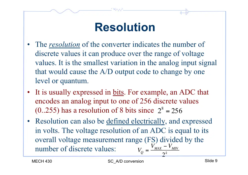
• The resolution of the converter indicates the number of
discrete values it can produce over the range of voltage
values. It is the smallest variation in the analog input signal
that would cause the A/D output code to change by one
level or quantum.
• It is usually expressed in bits. For example, an ADC that
encodes an analog input to one of 256 discrete values
(0..255) has a resolution of 8 bits since
• Resolution can also be defined electrically, and expressed
in volts. The voltage resolution of an ADC is equal to its
overall voltage measurement range (FS) divided by the
number of discrete values:
256
28 =
VQ = VMAX − VMIN
2k
- +
MECH 430
SC_A/D conversion
Slide 10
Resolution
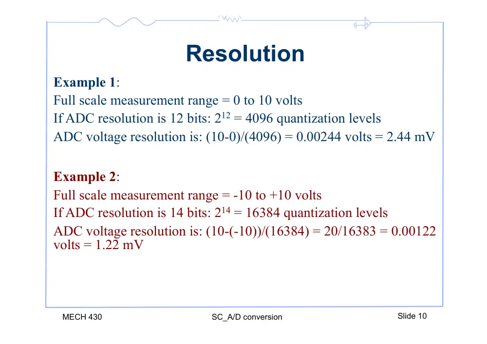
Example 1:
Full scale measurement range = 0 to 10 volts
If ADC resolution is 12 bits: 212 = 4096 quantization levels
ADC voltage resolution is: (10-0)/(4096) = 0.00244 volts = 2.44 mV
Example 2:
Full scale measurement range = -10 to +10 volts
If ADC resolution is 14 bits: 214 = 16384 quantization levels
ADC voltage resolution is: (10-(-10))/(16384) = 20/16383 = 0.00122
volts = 1.22 mV
- +
MECH 430
SC_A/D conversion
Slide 11
Resolution
• In practice, the resolution of the converter is limited by
the signal-to-noise (SNR) ratio of the signal in question.
• If there is too much noise present in the analog input, it
will be impossible to accurately resolve beyond a certain
number of bits of resolution, the “Effective Number Of
Bits" (ENOB).
• While the ADC will produce a result, the result is not
accurate, since its lower bits are simply measuring
noise.
- +
Input-Output Mapping
• Any input voltage vi is translated to its decimal equivalent
N as:
MECH 430
Introduction
Slide 12
N = INT
2k
FS × vi − VRL
[
]
#
$%
&
'(
• Going the other way around, to find an analog voltage
corresponding to a specific output N we use:
vi = N ×
FS
2k
"
#$
%
&' + VRL
FS = xMAX − xMIN
(1)
We will see what this is
shortly
- +
MECH 430
SC_A/D conversion
Slide 13
A/D Conversion Relations
• Equation (1) can be stated as:
• The decimal equivalent to a binary output N = bn…b1b0
bi is its bit value
wi is its weight
•
For example if N = 10110010:
- +
MECH 430
SC_A/D conversion
Slide 14
A/D Conversion Relations
• Now to find the voltage corresponding to a binary output
N :
• For example if a unipolar 8-bit ADC with FS = 5V
generates a binary code of 01001110 (78) the
corresponding voltage value is.
vi = (0 × 2−1 +1× 2−2 + 0 × 2−3 + 0 × 2−4 +1× 2−5 +1× 2−6 +1× 2−7 + 0 × 2−8) × 5 + 0 = 1.5234V
- +
MECH 430
SC_A/D conversion
Slide 15
Example 3
Minimum value
(Offset)
Maximum
value
Range
(FS)
Unipolar A/D
0V
5V
5V
Bipolar A/D
-2.5V
+12.5V
15V
4-20 mA transmitters
4mA
20mA
16mA
k-bits
VQ (%FS) LSB voltage for
FS = 5V
4
6.25
312mV
8
0.3906
19.5mV
10
0.0977
4.90mV
12
0.0244
1.20mV
14
0.00610
305µV
16
0.00153
75µV
- +
Example 4
•
Assume digitization of a unipolar signal that can change between 0 and 5
Volts into a 3 bit digital equivalent. Calculate the resolution, the number of
quantized levels. (Answer: Res=0.625, Levels=8)
•
Fill the table
•
What is the maximum error that the output voltage can undertake? ()
•
What will the maximum error be if we increased the number of bits to 4 in
the previous example? Verify that the error decreases with increasing the
number of bits. ()
MECH 430
Introduction
Slide 16
- +
Digital to Analog Conversion
• To find the analog voltage corresponding to the a
specific output N, we use:
• Analog values within a quantum level generate the
same output code. The maximum error is ±½LSB
(Least Significant Bit). The error VE between the
digitized voltage and the input voltage is estimated
by:
• The error can be lowered by increasing the number of
output bits of the converter
MECH 430
Introduction
Slide 17
vi = N ×
FS
2k
"
#$
%
&' + VRL
- +
MECH 430
SC_A/D conversion
Slide 18
Accuracy
•
An ADC has several sources of errors:
1) Quantization error caused by the finite number of levels
(quanta)
2) Non-linearity error caused by imperfections in the IC
manufacturing
3) Aperture error which is due to a clock jitter (significant at
high frequencies).
• These errors are measured in a unit called the Least
Significant Bit (LSB). For example, for an eight-bit
ADC, an error of one LSB is 1/256 of the full signal
range, or about 0.4%
- +
MECH 430
SC_A/D conversion
Slide 19
Quantization Error
• The quantization error is the error between the analog
value and its digitized representation:
VE
Vx
VQ
Q
X
E
NV
V
V
−
=
• The minimum number of bits required in the ADC for
a specific allowable error VQ is (truncated to the next
highest integer value):
k =
log VMAX − VMIN
[
] /VQ +1
(
)
log(2)
- +
Example 5
• An ADC is used to sample the output voltage of a
pressure transducer. The output of the sensor is 0
Volts when the pressure is 0kPa and 10Volts when
the pressure reaches 10kPa.
• If the sensor error is not to exceed 0.01kPa and
assuming the input of the ADC can match the output
of the sensor, select the number of ADC bits needed:
MECH 430
Introduction
Slide 20
k =
log
10
0.01 +1
!
"#
$
%&
log(2)
= 9.97
Choose k =10bits
- +
MECH 430
SC_A/D conversion
Slide 21
Example 6
• A temperature sensor generates an output that varies
within -0.5V<VS<+2V as the temperature varies from
-50oC to 200oC. The sensor gain is 0.01V/oC. The
ADC has 8bits and voltage reference -5V and +5V.
Discuss the characteristics of this system.
Solution:
• The sensor voltage Vs is matched to the input voltage
of the A/D converter by Vx = mVs+b
−0.5m + b = −5V
2m + b = 5V
3
;4
= −
=
⇒
b
m
3
4
−
=
⇒
S
X
V
V
- +
MECH 430
SC_A/D conversion
Slide 22
Example 6
Span:
Step size:
Resolution:
• For example at T = 50oC, the input of the ADC is:
VX = [0.01V/oC) x 50oC]x4 - 3V = -1.0V
5.0-(-5.0V)=10.0V; 200oC-(-50oC)=250oC
10.0V/256 = 39.1mV; 250oC/256 = 0.98oC
39.1mV at 8-bit; 0.98 oC at 8-bit
The equivalent digital output is:
(-1.0V-(-5V))/(0.039V) = 102 (decimal)
= 01100110 (binary)
• Therefore, the properties of this ADC are:
Number of quantized values
- +
MECH 430
SC_A/D conversion
Slide 23
Matching
• When connecting an input signal to an A/D converter
we must take care to match the signals.
• For example adapt a bipolar signal to a unipolar ADC
by scaling and adding an offset to the input:
VS
+5
+2.5
+0
-2.5
-5
0.5VS
+2.5
+0
-2.5
+5
+2.5
0
0.5(VS+5)
Input signal
ADC input
signal
+
-
-1
-1
Input
signal
VS
5V
2R
2R
R
ADC
input
signal
Op-amp implementation
- +
MECH 430
SC_A/D conversion
Slide 24
Example 7
Given:
An IC temperature sensor with a gain of 5mV/oC is
used to measure the temperature of an object up to
100oC. The sensor output is to be sent to an 8-bit ADC
with a 0V-10V reference.
Find:
Design the required signal conditioning to interface the
sensor signal to the A/D and determine the temperature
resolution.
- +
MECH 430
SC_A/D conversion
Slide 25
Example 7
Solution:
At 100oC, N = 11111111
Therefore the maximum value converted from the ADC:
VX = 10 2−1 + 2−2 + 2−3 + 2−4 + 2−5 + 2−6 + 2−7 + 2−8
(
) = 9.9609375V
But we have the maximum output of the sensor is:
VS(max) = 5mV /o C
(
) ×100oC = 0.5V
And the required amplification is:
19.92
5.0
.9 9609375
=
A =
- +
MECH 430
SC_A/D conversion
Slide 26
Example 7
• This amplification may be implemented via a non-
inverting op-amp with Rf = 18.92kΩ and Ri = 1kΩ
• Finally, the temperature resolution that is possible is:
ΔT = VQ
A
1
5mV /o C =
10 / 28
(
)
19.92
1
5 10−3
(
)
= 0.39oC
amplification
resolution
gain
- +
MECH 430
SC_A/D conversion
Slide 27
Sampling Rate
• The analog signal is continuous in time and it is
necessary to convert this to a flow of digital values.
• It is therefore required to define the rate at which new
digital values are sampled from the analog signal.
• The rate of new values is called the sampling rate or
sampling frequency of the converter.
- +
MECH 430
SC_A/D conversion
Slide 28
Sampling Rate
• There is no way of knowing, by looking at the output,
what the input was doing between one sampling
instant and the next.
• This faithful reproduction is only possible if the
sampling rate is higher than twice the highest
frequency of the signal. This is essentially what is
embodied in the Shannon-Nyquist sampling theorem.
- +
MECH 430
SC_A/D conversion
Slide 29
Sampling Rate
• If the input is known to be changing slowly compared to
the sampling rate, then it can be assumed that the value
of the signal between two sample instants was
somewhere between the two sampled values.
• If, however, the input signal is changing fast compared
to the sample rate, then this assumption is not valid.
- +
Aliasing
• Aliasing is the misrepresentation of a high frequency
signal as a low frequency one. This might happen
when we use an ADC as shown in the figure below.
• To avoid aliasing, the sampling frequency fs should be
more than twice the highest frequency of the sampled
analog signal. The sampling frequency of the analog
signal fo affects the accuracy of the discrete time
representation of the signal. For a reliable
approximation, the sampling frequency should be 5 to
10 times the analog signal frequency
MECH 430
Introduction
Slide 30
- +
Aliasing
MECH 430
Introduction
Slide 31
TS
T0
fS = 1/TS
Sampling
times
f0 = 1/T0
Apparent signal
(frequency fA)
- +
MECH 430
SC_A/D conversion
Slide 32
How to avoid aliasing
• To avoid aliasing make sure the sampling frequency fs
is twice the highest frequency present in the signal.
This condition is known as the Nyquist criterion:
2 fmax
fs >
• A Rule of thumb is to have the sampling rate at least 5
to 10 times that of the highest frequency in order to
accurately reproduce the waveform.