
EECE 210 Chapter 1, Fall 2012
American University of Beirut · Electric Circuits · 15 pages




Showing the first 10 of 15 pages. Download the PDF to see all of it.
More EECE 210 files
- Chapter Uploading Chapter 08 Sinusoidal Steady · Spring 2015ChapterView
- Homework All Chapters · Fall 2015ChapterView
- Chapter 2 · Fall 2012ChapterView
- Chapter 3 · Fall 2012ChapterView
- Chapter 4 · Fall 2012ChapterView
- Chapter 5 · Fall 2012ChapterView
- Chapter 6 · Fall 2012ChapterView
- Chapter 7 · Fall 2012ChapterView
Show the text of this chapter
Chapter 1
Circuit Variables and Elements
1.1
Electric Current
Definition
Current is the rate of flow of electric charge.
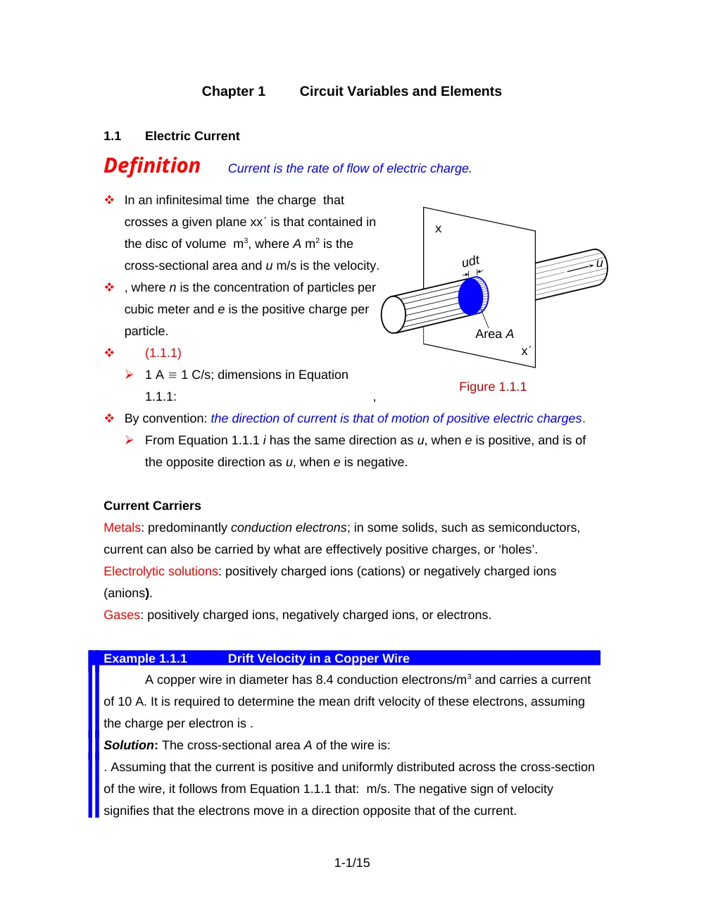
In an infinitesimal time the charge that
crosses a given plane xx is that contained in
the disc of volume m3, where A m2 is the
cross-sectional area and u m/s is the velocity.
, where n is the concentration of particles per
cubic meter and e is the positive charge per
particle.
(1.1.1)
1 A 1 C/s; dimensions in Equation
1.1.1:
,
By convention: the direction of current is that of motion of positive electric charges.
From Equation 1.1.1 i has the same direction as u, when e is positive, and is of
the opposite direction as u, when e is negative.
Current Carriers
Metals: predominantly conduction electrons; in some solids, such as semiconductors,
current can also be carried by what are effectively positive charges, or ‘holes’.
Electrolytic solutions: positively charged ions (cations) or negatively charged ions
(anions).
Gases: positively charged ions, negatively charged ions, or electrons.
Example 1.1.1
Drift Velocity in a Copper Wire
A copper wire in diameter has 8.4 conduction electrons/m3 and carries a current
of 10 A. It is required to determine the mean drift velocity of these electrons, assuming
the charge per electron is .
Solution: The cross-sectional area A of the wire is:
. Assuming that the current is positive and uniformly distributed across the cross-section
of the wire, it follows from Equation 1.1.1 that: m/s. The negative sign of velocity
signifies that the electrons move in a direction opposite that of the current.
1-1/15
x
Figure 1.1.1
udt
Area A
x
u
1.2
Voltage
Definition
The voltage between two points is the difference in electric
potential energy per unit charge, between these points.
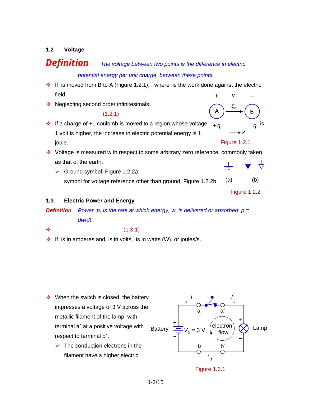
If is moved from B to A (Figure 1.2.1), , where is the work done against the electric
field.
Neglecting second order infinitesimals:
(1.2.1)
If a charge of +1 coulomb is moved to a region whose voltage
is
1 volt is higher, the increase in electric potential energy is 1
joule.
Voltage is measured with respect to some arbitrary zero reference, commonly taken
as that of the earth.
Ground symbol: Figure 1.2.2a;
symbol for voltage reference other than ground: Figure 1.2.2b.
1.3
Electric Power and Energy
Definition
Power, p, is the rate at which energy, w, is delivered or absorbed: p =
dw/dt.
(1.3.1)
If is in amperes and is in volts, is in watts (W), or joules/s.
When the switch is closed, the battery
impresses a voltage of 3 V across the
metallic filament of the lamp, with
terminal a at a positive voltage with
respect to terminal b.
The conduction electrons in the
filament have a higher electric
1-2/15
A
x
v
Figure 1.2.1
+ q
– q
+
–
A
B
x
(a)
(b)
Figure 1.2.2
a
a
b
b
VB = 3 V
Figure 1.3.1
Battery
Lamp
– I
I
I
electron
flow
+
+
–
–
potential energy at b than at a. The force of the electric field will therefore drive
them down an electric potential energy difference from b to a through the
filament. This loss of electric potential energy is converted to heat in the filament,
causing it to glow and emit light.
In the battery, the chemical reactions of the battery expend energy to move the
electrons up an electric potential energy difference from a to b.
P = VBI = (3 V)(0.25 A) = 0.75 W.
Example 1.3.1
Flashlight Circuit
If the current is 0.25 A in the circuit of Figure 1.3.1, how many electrons, on
average, pass through the lamp per second? What is the electric potential energy of an
electron at a relative to that at b? How much energy does the battery deliver in 1 hour?
Solution: A current of +0.25 A in the direction shown corresponds to an electron flow
through the lamp of Since the charge of the electron is it follows that electrons/s flow
through the lamp, on average.
The electric potential energy difference is the charge times the voltage.
Considering the electric potential energy at b to be at zero reference, the electric
potential energy of an electron at a is: Because it is negatively charged, the electron has
greater potential energy at b than at a.
Since P = 0.75 W, the energy delivered in one hour is J/hr.
Example 1.3.2
Discharge of Battery
An A-
size, 1.5 V
battery is rated
at 3 ampere-
hours (Ah).
During
continuous use,
with the battery
supplying a
current of 100 mA, the battery voltage stays substantially constant at 1.5 V for the first
1-3/15
Figure 1.3.2
t , hr
10
20
30
t , hr
1.50
1.25
100
80
10
20
30
IB , mA
VB , V
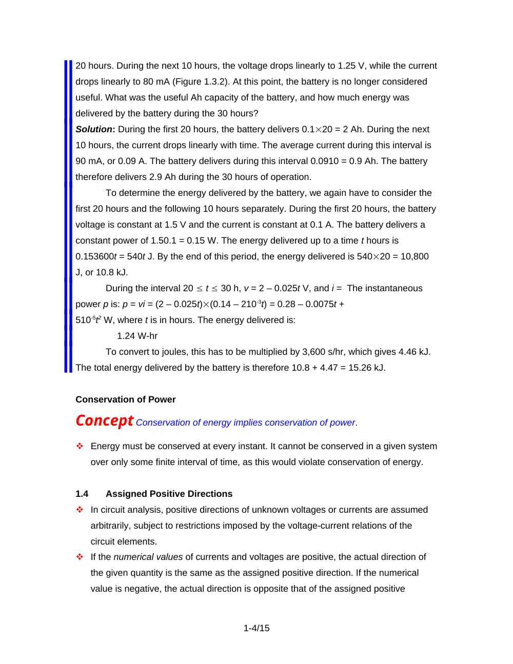
20 hours. During the next 10 hours, the voltage drops linearly to 1.25 V, while the current
drops linearly to 80 mA (Figure 1.3.2). At this point, the battery is no longer considered
useful. What was the useful Ah capacity of the battery, and how much energy was
delivered by the battery during the 30 hours?
Solution: During the first 20 hours, the battery delivers 0.120 = 2 Ah. During the next
10 hours, the current drops linearly with time. The average current during this interval is
90 mA, or 0.09 A. The battery delivers during this interval 0.0910 = 0.9 Ah. The battery
therefore delivers 2.9 Ah during the 30 hours of operation.
To determine the energy delivered by the battery, we again have to consider the
first 20 hours and the following 10 hours separately. During the first 20 hours, the battery
voltage is constant at 1.5 V and the current is constant at 0.1 A. The battery delivers a
constant power of 1.50.1 = 0.15 W. The energy delivered up to a time t hours is
0.153600t = 540t J. By the end of this period, the energy delivered is 54020 = 10,800
J, or 10.8 kJ.
During the interval 20 t 30 h, v = 2 – 0.025t V, and i = The instantaneous
power p is: p = vi = (2 – 0.025t)(0.14 – 210-3t) = 0.28 – 0.0075t +
510-5t2 W, where t is in hours. The energy delivered is:
1.24 W-hr
To convert to joules, this has to be multiplied by 3,600 s/hr, which gives 4.46 kJ.
The total energy delivered by the battery is therefore 10.8 + 4.47 = 15.26 kJ.
Conservation of Power
Concept Conservation of energy implies conservation of power.
Energy must be conserved at every instant. It cannot be conserved in a given system
over only some finite interval of time, as this would violate conservation of energy.
1.4
Assigned Positive Directions
In circuit analysis, positive directions of unknown voltages or currents are assumed
arbitrarily, subject to restrictions imposed by the voltage-current relations of the
circuit elements.
If the numerical values of currents and voltages are positive, the actual direction of
the given quantity is the same as the assigned positive direction. If the numerical
value is negative, the actual direction is opposite that of the assigned positive
1-4/15
direction.
Concept If current i is in the direction of a voltage drop v, then the power p = vi
represents power absorbed by the element through which i flows.
Conversely, If i is in the direction of a voltage rise v then the power p
represents power delivered by the element through which i flows.
Negative power delivered is power that is actually absorbed, and negative power
absorbed is power that is actually delivered.
Negative values of current, voltage, or power are perfectly natural in circuit analysis.
Example 1.4.1
Assigned Positive Directions of Current and Voltage
Assume that
in the case of the
flashlight discussed
above, the battery is
contained in a box
having unmarked
terminals, so we do
not know which
terminal is positive
and which is
negative. Suppose we decide to assign the positive direction of VB as
shown in Figure 1.4.1a. It would then be reasonable to assign the positive direction of
as before, that is, flowing into the lamp at a.
Suppose that when the current is measured in the assigned positive direction it
is found to be 0.25 A in the direction opposite to that assumed, which means that
I = -0.25 A. This would seem to indicate that the positive terminal of the battery is b and
its negative terminal is a. We confirm this by measuring the battery voltage in the
assigned positive direction. So . From Figure 1.4.1a, the assigned positive direction of is
in the direction of a voltage drop VB in the lamp and a voltage rise VB in the battery.
Hence, according to Equation 1.3.1, the power absorbed by the lamp, and that delivered
by the battery, is as before.
Suppose we had assigned the positive directions of VB and as shown in Figure
1.4.1b, so is now in the direction of a voltage rise VB in the lamp and a voltage drop VB
1-5/15
(a)
b
b
I
VB = – 3 V
a
a
Battery
I = – 0.25 A
Battery
Figure 1.4.1
(b)
a
a
VB = – 3 V
b
b
I = 0.25 A
I
+
+
–
–
in the battery. The same measurements as above, in the assigned positive directions,
would give I = 0.25 A, and VB = -3 V. Equation 1.3.1 now gives: as the power delivered
by the lamp and absorbed by the battery. The negative sign means that a power of 0.75
W is in fact absorbed by the lamp and delivered by the battery, as before.
It is seen that Equation 1.3.1 gives the same value of power absorbed by the
lamp or delivered by the battery, irrespective of the assigned positive directions of and
as long as Equation 1.3.1 is interpreted correctly in terms of actual values, whether
measured or calculated.
1.5
Active and Passive Circuit Elements
Definition
Active devices can generate electrical energy through conversion
from another source of energy, whereas passive devices cannot.
Active devices, such as batteries and generators, are represented in electric circuits
by voltage or current sources. Examples of passive circuit elements are resistors,
capacitors, and inductors.
1.6
Voltage and Current Sources
Definition
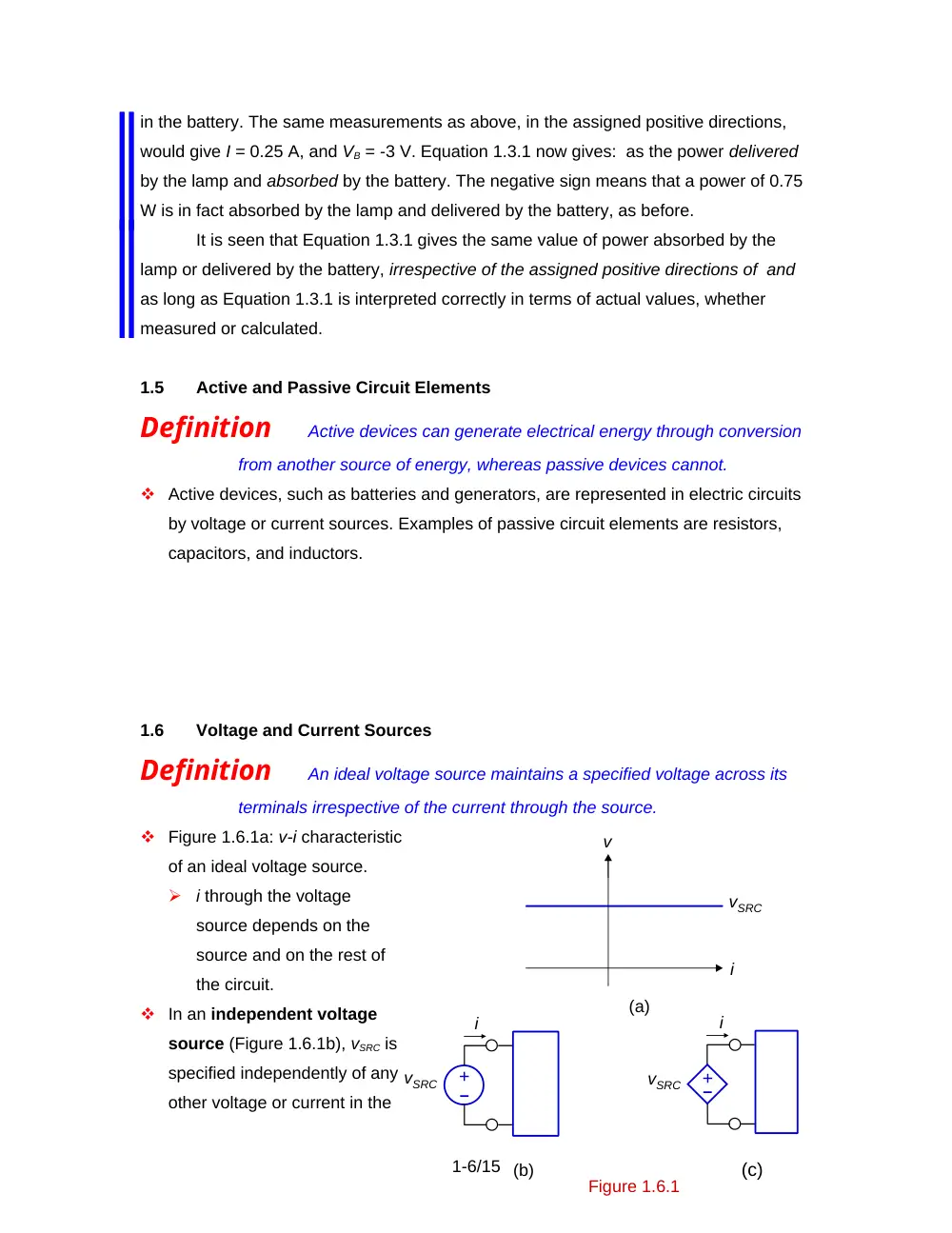
An ideal voltage source maintains a specified voltage across its
terminals irrespective of the current through the source.
Figure 1.6.1a: v-i characteristic
of an ideal voltage source.
i through the voltage
source depends on the
source and on the rest of
the circuit.
In an independent voltage
source (Figure 1.6.1b), vSRC is
specified independently of any
other voltage or current in the
1-6/15
(a)
v
i
i
(b)
(c)
Figure 1.6.1
vSRC
i
vSRC
vSRC
–
+
+–
circuit.
In a dependent voltage source (Figure 1.6.1c), vSRC depends on another voltage or
current in the circuit.
In a voltage-controlled voltage source (VCVS), vSRC depends on another
voltage, e.g., .
In a current-controlled voltage source (CCVS), vSRC depends on another
current, e.g., .
Definition
An ideal
current source
maintains a specified
current through it
irrespective of the
voltage across its
terminals.
Figure 1.6.2a: v-i characteristic
of an ideal current source.
v across the current
source depends on the
source and on the rest of
the circuit.
In an independent current source (Figure 1.6.2b), iSRC is specified independently of
any other voltage or current in the circuit.
In a dependent current source (Figure 1.6.2c), iSRC depends on another voltage or
current in the circuit.
In a voltage-controlled current source (VCCS), iSRC depends on another
voltage, e.g., .
In a current-controlled current source (CCCS), iSRC depends on another
current, e.g., .
Interconnection of Sources
Concept A connection of sources that violates conservation of energy or
conservation of charge is invalid and is not allowed in electric circuits.
1-7/15
v
(a)
v
(b)
(c)
v
iSRC
iSRC
iSRC
i
+
+
–
–
Figure 1.6.2
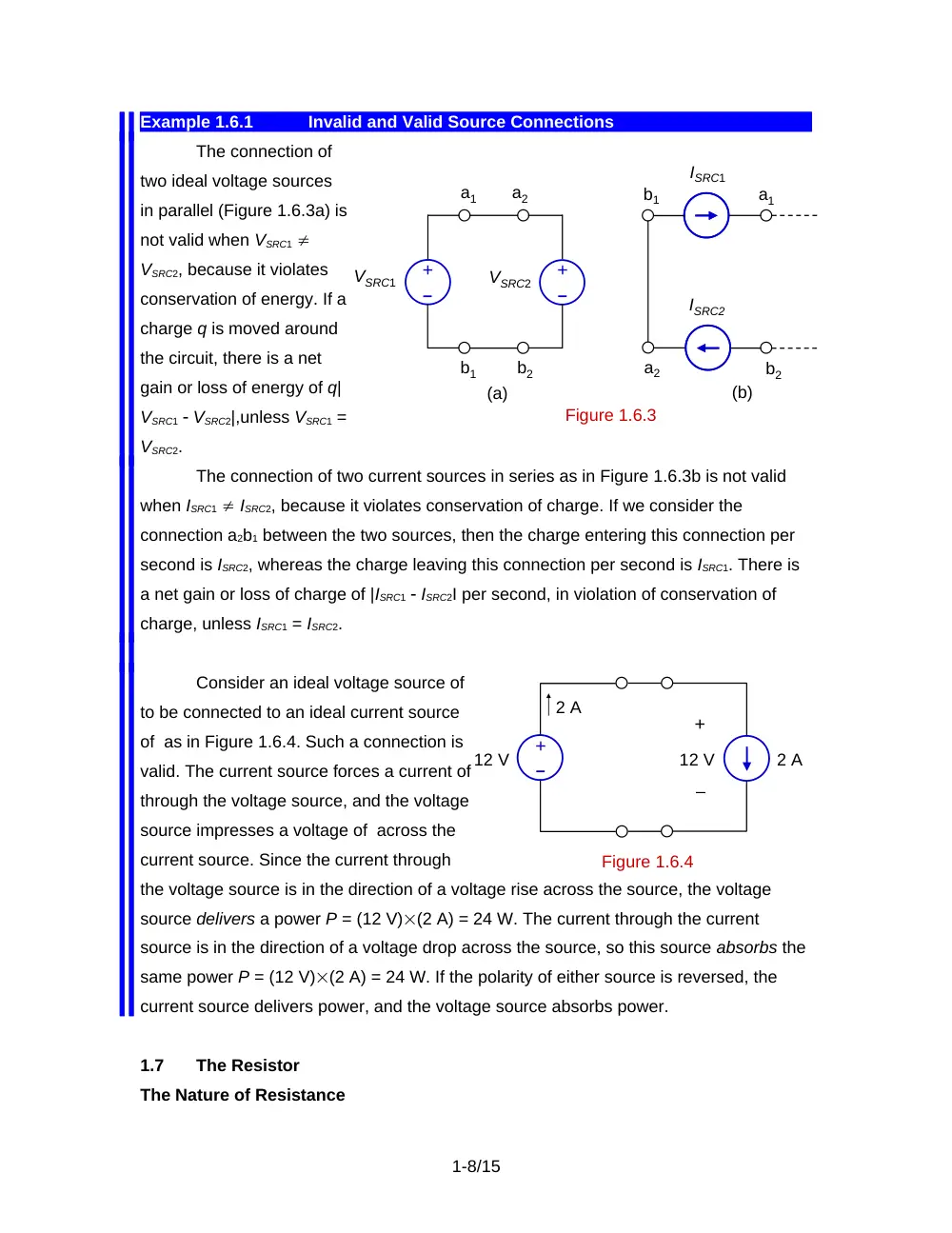
Example 1.6.1
Invalid and Valid Source Connections
The connection of
two ideal voltage sources
in parallel (Figure 1.6.3a) is
not valid when VSRC1
VSRC2, because it violates
conservation of energy. If a
charge q is moved around
the circuit, there is a net
gain or loss of energy of q|
VSRC1 VSRC2|,unless VSRC1 =
VSRC2.
The connection of two current sources in series as in Figure 1.6.3b is not valid
when ISRC1 ISRC2, because it violates conservation of charge. If we consider the
connection a2b1 between the two sources, then the charge entering this connection per
second is ISRC2, whereas the charge leaving this connection per second is ISRC1. There is
a net gain or loss of charge of |ISRC1 ISRC2I per second, in violation of conservation of
charge, unless ISRC1 = ISRC2.
Consider an ideal voltage source of
to be connected to an ideal current source
of as in Figure 1.6.4. Such a connection is
valid. The current source forces a current of
through the voltage source, and the voltage
source impresses a voltage of across the
current source. Since the current through
the voltage source is in the direction of a voltage rise across the source, the voltage
source delivers a power P = (12 V)(2 A) = 24 W. The current through the current
source is in the direction of a voltage drop across the source, so this source absorbs the
same power P = (12 V)(2 A) = 24 W. If the polarity of either source is reversed, the
current source delivers power, and the voltage source absorbs power.
1.7
The Resistor
The Nature of Resistance
1-8/15
Figure 1.6.3
–
VSRC1
VSRC2
a1
a2
b2
b1
(a)
ISRC1
–
(b)
+
+
a1
a2
b1
b2
ISRC2
2 A
12 V
2 A
12 V
–
+
+
–
Figure 1.6.4
Concept Electrical resistance is due to impediments to the flow of conduction
electrons under the influence of an applied electric field.
These impediments can be considered to be due to ‘collisions’ between conduction
electrons accelerated by the applied electric field and metal atoms of the crystal,
which vibrate about their rest positions with an amplitude that increases with
temperature.
As a result of these collisions: i) electrons loose kinetic energy. But because their
velocities increase between collisions, the net effect is that they acquire a mean drift
velocity that is superposed on their much larger random thermal velocities; ii) the
metal atoms gain kinetic energy so they vibrate with a larger amplitude. This is
reflected as an increase in the temperature of the metal.
The electrical resistance R of a conductor is the ratio of the voltage v applied to the
conductor to the resulting current i in the conductor. Thus:
(1.7.1)
When v is expressed in volts and i in amperes, R is in ohms and is denoted by
the symbol .
The reciprocal of the resistance R is the conductance G:
(1.7.2)
When v is expressed in volts and i in amperes, G is in siemens, denoted by the
symbol S.
Ohm’s Law. For metals at a given temperature, R is constant over a wide range of v
and i:
(1.7.3)
An ideal resistor obeys Ohm’s law and has a linear v-i characteristic whose slope is
R (Figure 1.7.1a).
Since such a resistor dissipates power, the assigned positive direction of current i is
always in the direction of the voltage drop v across the resistor. With v and i positive
quantities, R in Equation 1.7.3 is a positive quantity for a passive resistor.
A connection of zero
resistance, or infinite
conductance, is a short
circuit, whereas a connection
1-9/15
v
i
(a)
(b)
v
R
slope = R
i
+
–
of infinite resistance, or zero conductance, is an open circuit, since there will be no
current flow.
Power Dissipated
Substituting from Equation 1.7.2 or Equation 1.7.3 in Equation 1.1.1 gives for the
power absorbed by a resistor:
(1.7.4)
When is in volts, is in amperes, in ohms, and is in siemens, the power
dissipated is in watts.
Temperature Effect
The resistance of a metal increases with temperature, because of the increased
amplitude of vibration of metal ions. As a result, the probability of collision increases,
the mean time between collisions decreases, the drift velocity and current decrease,
and the resistance increases.
The variation of the resistance of a metal with temperature is given by:
(1.7.5)
1.8
The Capacitor
Concept The fundamental attribute of a capacitor is its ability to store energy in the
electric field resulting from separated positive and negative electric charges.
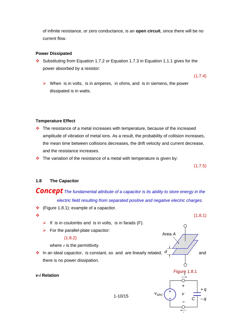
(Figure 1.8.1): example of a capacitor.
(1.8.1)
If is in coulombs and is in volts, is in farads (F).
For the parallel-plate capacitor:
(1.8.2)
where is the permittivity.
In an ideal capacitor, is constant, so and are linearly related,
and
there is no power dissipation.
v-i Relation
1-10/15
Figure 1.8.1
Area A
d
i
C
i
+ q
– q
v
vSRC
+
–
–
+
For the assigned positive directions in Figure 1.8.2, . Substituting in Equation 1.8.1:
, or
(1.8.3)
C must be a positive quantity for a passive capacitor.
Concept Passive Sign Convention: If the assigned positive direction of current
through a passive circuit element is in the direction of a voltage drop across
the element, a positive sign is used in the v-i relation of that circuit element. If
the assigned positive direction of current through the element is in the
direction of a voltage rise across the element, a negative sign is used in the
v-i relation of that circuit element.
A positive sign is used in the v-i relation of a resistor and in Equation 1.8.3 for the
assigned positive direction of Figure 1.8.2.
If in Figure 1.8.2, q increases with time, so current must be flowing into the positive
terminal of the capacitor and out of the negative terminal. According to the power
flow convention, power is absorbed by the capacitor and stored as electric energy.
The values of i and are both positive, so C is positive.
If v > 0, the charge on the capacitor decreases with time, so current must be flowing
out of the positive terminal of the capacitor and into the negative terminal. The values
of and in Equation 1.8.3 are both negative, so remains a positive quantity. The
actual current is now in the direction of a voltage rise across the capacitor. This
means, according to the power flow convention that the capacitor is now returning to
the rest of the circuit energy that had been stored in it.
If the assigned positive direction of i or v is reversed in Figure 1.8.2, so that i is in the
direction of a voltage rise across the capacitor, then Equation 1.8.3 must be written
with a negative sign, so that C is positive for positive or negative .
Steady Voltage and Current
Concept When a dc voltage is applied to a capacitor, the resulting current through
the capacitor is zero, and the capacitor behaves as an open circuit as far as
the dc voltage is concerned.
For a dc voltage, , and the capacitor charge does not change with time. Hence, I = 0,
in accordance with Equation 1.8.3, which means that the capacitor behaves as an
1-11/15
open circuit as far as the dc voltage is concerned.
Stored Energy
The energy stored in the electric field of a capacitor is equal to work done in
separating the charges and.
From Equation 1.2.1, For a capacitor, and Substituting in the expression for
(1.8.4)
1.9
The Inductor
Concept The fundamental attribute of an inductor is its ability to store energy in the
magnetic field produced by a current.
A prototypical inductor is a coil of N turns that is wound
on a toroidal core of magnetic material (Figure 1.9.1).
Because of the toroidal shape, and if the winding is tight,
with negligible thickness of the wire and insulation, the
flux is confined to the core and links all the turns of the
coil, the flux linkage being equal to N.
The inductance L of the coil is defined as the flux linkage
per unit current of the coil, or:
= Li
(1.9.1)
When i is in amperes and is in weber-turns (Wb-turns), L is in henries (H).
In an ideal inductor, L is constant, so and i are linearly related, and there is no
power dissipation.
v-i Relation
If the flux changes with time, a voltage is induced in the coil whose magnitude is
given by Faraday’s law:
(1.9.2)
Substituting from Equation 1.9.1:
, or
(1.9.3)
L must be a positive quantity for a passive inductor.
1-12/15
v
i
i
Figure 1.9.1
+
–
According to Lenz’s law, the polarity of v due to a change in i
is such that it opposes the change in i. If v opposes the
increase in i by being a voltage drop in the direction of i
(Figure 1.9.2). Power is absorbed by the inductor and stored
as energy in the magnetic field; Equation 1.9.3 are written with
a positive sign.
If v opposes the decrease in i by being a voltage rise in the
direction of thereby adding to vSRC and aiding the flow of current. The inductor now
returns to the rest of the circuit, energy that had previously been stored. In both
cases, L is a positive quantity in Equation 1.9.3.
The passive sign convention applies, so that if the assigned positive direction of i is
in the direction of a voltage rise across the inductor, Equation 1.9.3 are written with a
negative sign, and L remains a positive quantity.
Example 1.9.1
Inductance of Toroidal Coil
Consider the toroidal core shown in Figure 1.9.1. Let the radius of the toroid be a
m, the cross-sectional area of the core be A m2, and its relative permeability be r. The
cross-sectional dimensions of the core are assumed to be small compared to a, so that
the magnetic field intensity H can be considered constant across the cross section of the
core. A coil of N turns is tightly wound around the core so that all the magnetic flux lies
entirely in the core. It is required to determine the inductance of the toroidal coil.
Solution: Consider a circle of radius r that lies inside the core. From ampere’s circuital
law: H2r = NI, where I is the current in the coil, so that:
(1.9.4)
The magnetic flux density B is:
(1.9.5)
where 0 is the permeability of free space (4107 henries/meter). Because the
dimensions of the core are small compared to that of the toroid, we may replace with so
that the flux in the core is:
(1.9.6)
The flux linkage is:
(1.9.7)
1-13/15
i
v
vSRC
L
+
–
–
+
Figure 1.9.2
It follows from Equation 1.9.1 that the inductance of the coil is:
(1.9.8)
Steady Voltage and Current
Concept When a dc current flows through an inductor, the voltage across the
inductor is zero, and the inductor behaves as a short circuit as far as the dc
current is concerned.
When the current is dc, , and the flux does not change with time. Hence, V = 0,
which means that the inductor behaves as a short circuit.
Stored Energy
If the current in the inductor, and hence the flux linkage are positive and increasing
with time, the power input to the inductor is: The work done in increasing from 0 at
to at time which equals the energy stored in the magnetic field, is:
(1.9.9)
1.10
Concluding Remarks
Fundamentally, the three basic circuit parameters of resistance, capacitance, and
inductance model three essential attributes of the electromagnetic field associated
with voltages and currents. These attributes are: power dissipation, energy stored in
the electric field, and energy stored in the magnetic field.
Electromagnetic fields are inherently distributed and travel in any electrical system as
waves at speeds that may approach that of light in vacuum. The wavelength equals
the speed of the wave divided by the frequency of the voltage and current signals.
As long as the physical dimensions of the system are small compared to the
wavelength, the wave nature of electric signals can be neglected. This is tantamount
to ignoring the distributed nature of the power dissipation, the energy stored in the
electric field, and that stored in the magnetic field. Each of these entities is then
separately lumped and represented by discrete circuit elements, namely, resistors,
capacitors, and inductors.
1-14/15
In basic circuit theory it is assumed that the circuit parameters – R, C, and L – are
constant, that is, they do not vary with current or voltage, nor with time, which makes
the corresponding v-i, v-q, or -i relations linear. The system is designated as linear,
time-invariant (LTI). A linear system obeys superposition.
Combinations of basic circuit elements are extremely useful not just for modeling but
also for signal processing, that is, modifying, in a prescribed manner, the
magnitude and time course of current or voltage signals.
1-15/15