
EECE 210 Chapter Uploading Chapter 08 Sinusoidal Steady, Spring 2015
American University of Beirut · Electric Circuits · 43 pages · Prof. Imad El Hajj

Showing the first 10 of 43 pages. Download the PDF to see all of it.
More EECE 210 files
Show the text of this chapter
Chapter 8
Sinusoidal Steady State
The present chapter is concerned with introducing a special methodology for
the analysis of a circuit excited by sinusoidal functions of time in the steady state.
The methodology is based on expressing voltages and currents as phasors and the
voltage-current relation of circuit elements in terms of impedance. Linear differential
equations describing the behavior of circuits involving capacitors and inductors are
thereby reduced to algebraic equations involving the imaginary unit j. This greatly
simplifies circuit analysis and extends to the sinusoidal steady state all the concepts,
theorems, and procedures applied to resistive circuits under dc conditions, in addition
to other advantages mentioned in Section 8.1.
The chapter is therefore mainly concerned with developing the concepts of
phasors and impedance and applying them in several illustrative examples.
8.1
The Sinusoidal Function
A voltage or a
current that varies
sinusoidally with time can
be represented as:
(8.1.1)
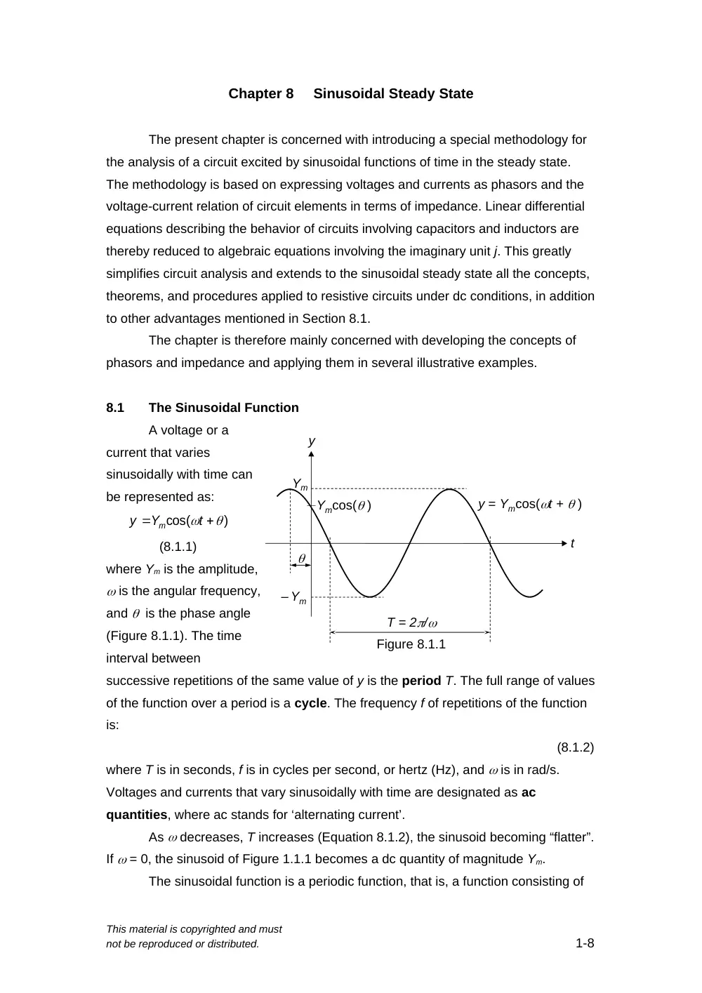
where Ym is the amplitude,
is the angular frequency,
and is the phase angle
(Figure 8.1.1). The time
interval between
successive repetitions of the same value of y is the period T. The full range of values
of the function over a period is a cycle. The frequency f of repetitions of the function
is:
(8.1.2)
where T is in seconds, f is in cycles per second, or hertz (Hz), and is in rad/s.
Voltages and currents that vary sinusoidally with time are designated as ac
quantities, where ac stands for ‘alternating current’.
As decreases, T increases (Equation 8.1.2), the sinusoid becoming “flatter”.
If = 0, the sinusoid of Figure 1.1.1 becomes a dc quantity of magnitude Ym.
The sinusoidal function is a periodic function, that is, a function consisting of
This material is copyrighted and must
not be reproduced or distributed.
1-8
y
Ym
T = 2/
Ymcos( )
Figure 8.1.1
– Ym
t
y = Ymcos(t + )
)
cos(
t
Y
y
m
cycles that repeat at a given frequency. However, it is the only periodic function that
has only a single frequency. In fact, according to Fourier’s theorem (Chapter 16), a
periodic function can generally be considered as the sum of a theoretically infinite
number of cosine and sine functions whose frequencies are integral multiples of the
frequency of the periodic function.
An important implication of this characteristic of sinusoidal functions is:
Concept: When a sinusoidal excitation is applied to an LTI circuit, all the
currents and voltages in the circuit are sinusoidal functions,
generally having different amplitudes and phase angles, but all
having the same frequency as the excitation.
The reason for this is that voltages and currents in an LTI circuit are subject to
linear operations such as: i) scaling, or multiplication by a constant, as in voltage or
current division, ii) addition and subtraction, as in KCL or KVL, and iii) differentiation
and integration, as in the v-i relations of inductors and capacitors. When sinusoidal
functions are subjected to any of these linear operations, they remain sinusoidal
functions of the same frequency. The amplitudes and phase angles of the resulting
sinusoidal functions will differ from those of the original functions, but no new
frequencies are produced.
Another important property of the sinusoidal function, which is used in this
chapter, is embodied in De Moivre’s theorem:
(8.1.3)
where j = is the imaginary unit and Ym is the amplitude of the sinusoidal function. is
a complex quantity, whose real component is Ymcost and whose imaginary
component is jYmsint. The term Ymsint, without j, is the imaginary part. The real
part and the real component are, of course,
one and the same.
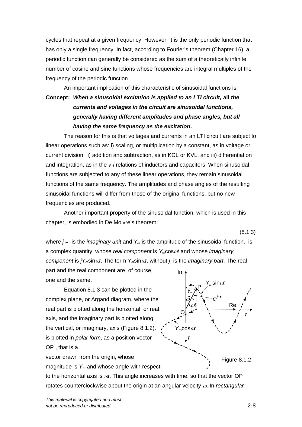
Equation 8.1.3 can be plotted in the
complex plane, or Argand diagram, where the
real part is plotted along the horizontal, or real,
axis, and the imaginary part is plotted along
the vertical, or imaginary, axis (Figure 8.1.2).
is plotted in polar form, as a position vector
OP , that is a
vector drawn from the origin, whose
magnitude is Ym and whose angle with respect
to the horizontal axis is t. This angle increases with time, so that the vector OP
rotates counterclockwise about the origin at an angular velocity . In rectangular
This material is copyrighted and must
not be reproduced or distributed.
2-8
Figure 8.1.2
Im
Re
P
Ym
t
t
t
Ymsint
Ymcost
O
t
je
form, Ymcost is the projection of along the real axis, and Ymsint is its projection on
the imaginary axis. As time progresses, the lengths of these projections vary
sinusoidally with time, as illustrated by the dashed extensions in Figure 8.1.2.
Analysis of the sinusoidal steady state is the derivation of the currents and
voltages in a circuit after a sinusoidal excitation has been applied for a sufficiently
long time. When any excitation is suddenly applied to a circuit, there is generally an
initial “transient”, or temporary, response that dies out with time, as explained in later
chapters. After this transient dies out, a steady-state remains, in which the currents
and voltages repeat according to some pattern that depends on the time variation of
the excitation.
Analysis of the sinusoidal steady state is of fundamental importance for the
following reasons:
1.
The sinusoidal steady state is used in several practical cases, as in the frequency
response of systems (Chapter 14) and in power systems analysis (Chapter 25).
Electric power is efficiently generated, transmitted, and distributed as sinusoidal
voltages.
2.
The methodology used in steady state sinusoidal analysis is based on expressing
sinusoidal voltages and currents as phasors and the v-i relations in terms of
impedance. This is extremely convenient in that it extends to the sinusoidal
steady state all the concepts, theorems, and procedures that apply to resistive
circuits under dc conditions.
3.
This representation of sinusoidal voltages and currents as phasors and the v-i
relations in terms of impedance are later applied to the analysis of frequency
responses of circuits (Chapter 14), the responses to periodic inputs (Chapter 16),
complex power and three-phase systems (Chapter 25), and the Fourier transform
(Chapter 22). Moreover, the same representation can be readily generalized to
the most powerful method for analyzing linear systems, namely that of the
Laplace transform (Chapter 21).
8.2
Phasors
Responses to Sinusoidal Excitations
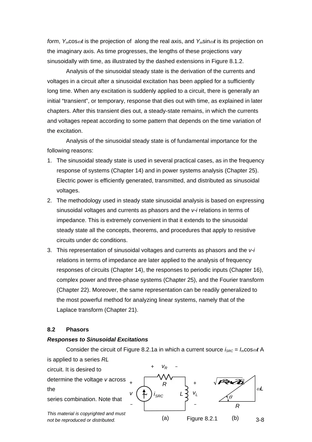
Consider the circuit of Figure 8.2.1a in which a current source iSRC = Imcost A
is applied to a series RL
circuit. It is desired to
determine the voltage v across
the
series combination. Note that
This material is copyrighted and must
not be reproduced or distributed.
3-8
R
L
iSRC
+
–
+
–
+
–
v
vR
vL
Figure 8.2.1
(a)
(b)
R
L
2
2 2
L
R
R1
ISRC
Figure 8.2.2
+
–
V
R2
a tilde symbol is added to the source to denote a steady sinusoidal excitaion.
From KVL, v = vR + vL, where vR = RiSRC and vL = LdiSRC/dt. KVL becomes:
(8.2.1)
Substituting, iSRC = Imcost,
(8.2.2)
To combine the sine and cosine terms into a single function, the RHS is
multiplied and divided by to give:
(8.2.3)
We now define an angle whose cosine is and sine is (Figure 8.2.1b).
Equation 8.2.3 becomes:
(8.2.4)
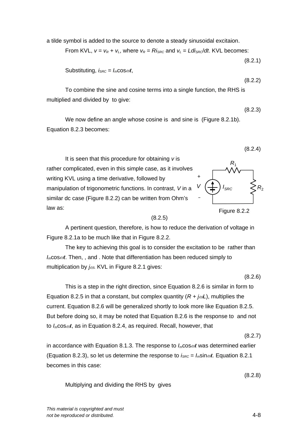
It is seen that this procedure for obtaining v is
rather complicated, even in this simple case, as it involves
writing KVL using a time derivative, followed by
manipulation of trigonometric functions. In contrast, V in a
similar dc case (Figure 8.2.2) can be written from Ohm’s
law as:
(8.2.5)
A pertinent question, therefore, is how to reduce the derivation of voltage in
Figure 8.2.1a to be much like that in Figure 8.2.2.
The key to achieving this goal is to consider the excitation to be rather than
Imcost. Then, , and . Note that differentiation has been reduced simply to
multiplication by j. KVL in Figure 8.2.1 gives:
(8.2.6)
This is a step in the right direction, since Equation 8.2.6 is similar in form to
Equation 8.2.5 in that a constant, but complex quantity (R + jL), multiplies the
current. Equation 8.2.6 will be generalized shortly to look more like Equation 8.2.5.
But before doing so, it may be noted that Equation 8.2.6 is the response to and not
to Imcost, as in Equation 8.2.4, as required. Recall, however, that
(8.2.7)
in accordance with Equation 8.1.3. The response to Imcost was determined earlier
(Equation 8.2.3), so let us determine the response to iSRC = Imsint. Equation 8.2.1
becomes in this case:
(8.2.8)
Multiplying and dividing the RHS by gives
This material is copyrighted and must
not be reproduced or distributed.
4-8
or,
(8.2.9)
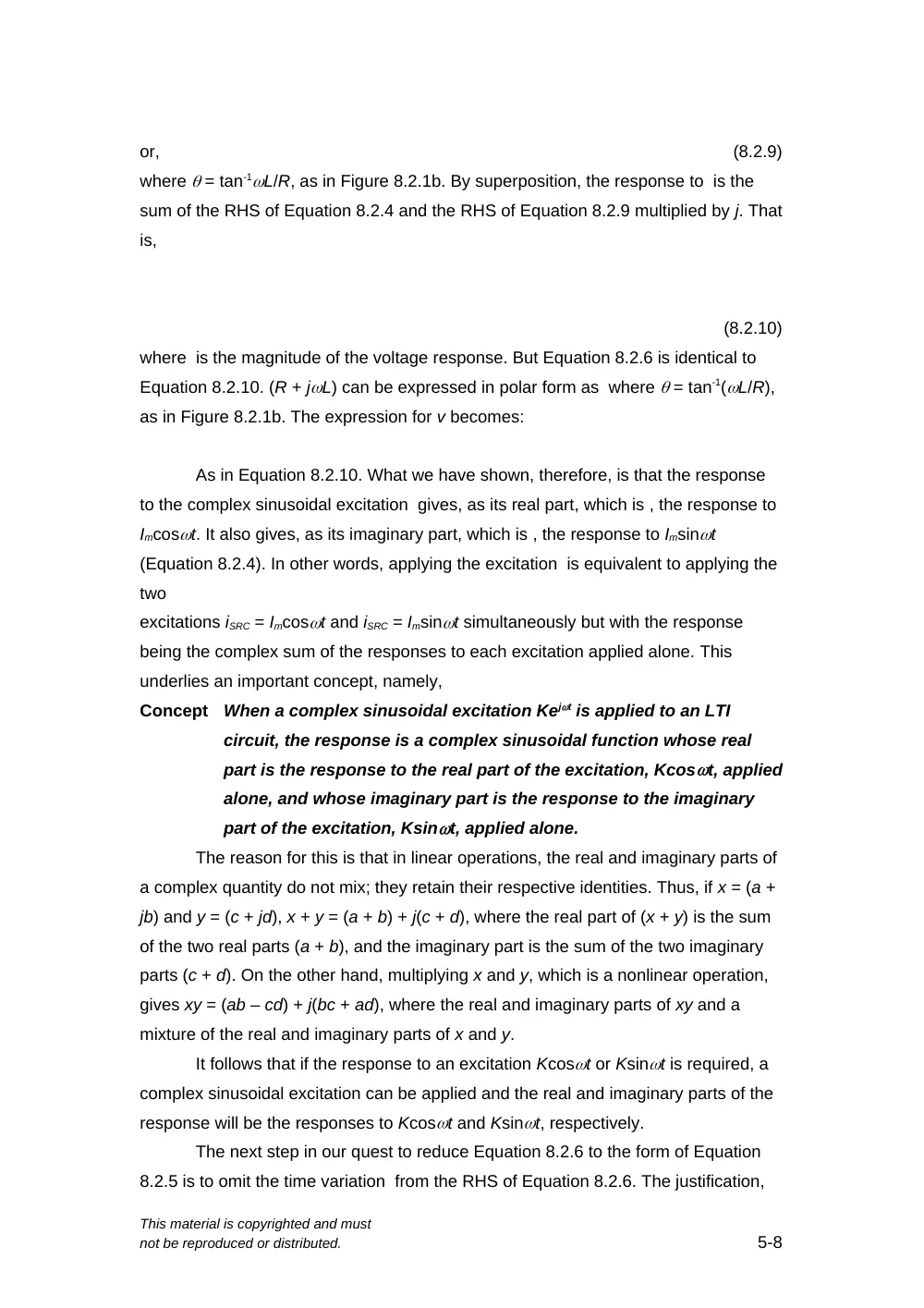
where = tan-1L/R, as in Figure 8.2.1b. By superposition, the response to is the
sum of the RHS of Equation 8.2.4 and the RHS of Equation 8.2.9 multiplied by j. That
is,
(8.2.10)
where is the magnitude of the voltage response. But Equation 8.2.6 is identical to
Equation 8.2.10. (R + jL) can be expressed in polar form as where = tan-1(L/R),
as in Figure 8.2.1b. The expression for v becomes:
As in Equation 8.2.10. What we have shown, therefore, is that the response
to the complex sinusoidal excitation gives, as its real part, which is , the response to
Imcost. It also gives, as its imaginary part, which is , the response to Imsint
(Equation 8.2.4). In other words, applying the excitation is equivalent to applying the
two
excitations iSRC = Imcost and iSRC = Imsint simultaneously but with the response
being the complex sum of the responses to each excitation applied alone. This
underlies an important concept, namely,
Concept
When a complex sinusoidal excitation Kejt is applied to an LTI
circuit, the response is a complex sinusoidal function whose real
part is the response to the real part of the excitation, Kcost, applied
alone, and whose imaginary part is the response to the imaginary
part of the excitation, Ksint, applied alone.
The reason for this is that in linear operations, the real and imaginary parts of
a complex quantity do not mix; they retain their respective identities. Thus, if x = (a +
jb) and y = (c + jd), x + y = (a + b) + j(c + d), where the real part of (x + y) is the sum
of the two real parts (a + b), and the imaginary part is the sum of the two imaginary
parts (c + d). On the other hand, multiplying x and y, which is a nonlinear operation,
gives xy = (ab – cd) + j(bc + ad), where the real and imaginary parts of xy and a
mixture of the real and imaginary parts of x and y.
It follows that if the response to an excitation Kcost or Ksint is required, a
complex sinusoidal excitation can be applied and the real and imaginary parts of the
response will be the responses to Kcost and Ksint, respectively.
The next step in our quest to reduce Equation 8.2.6 to the form of Equation
8.2.5 is to omit the time variation from the RHS of Equation 8.2.6. The justification,
This material is copyrighted and must
not be reproduced or distributed.
5-8
Figure 8.2.3
(a)
Im
Re
Im
(b)
Im
Re
t
)
(
j t
me
V
t
j
me
I
Im
j t
me
V
V
(c)
R
L
as explained earlier, is that when an LTI circuit is excited at a single frequency, all the
currents and voltages in the circuit will be sinusoids having the same given frequency
, but with different amplitudes and phase angles. No information is lost by omitting
the time variation . This leads to phasor notation, as will be elaborated next.
Phasor Notation
The complex excitation and the complex response (Equation 8.2.10) can be
plotted as position vectors on an Argand diagram (Figure 8.2.3a). Both vectors rotate
counterclockwise at an angular speed , retaining the phase angle between them
as they do so. The angular speed is the same, because as emphasized earlier, all
the voltage and current responses in an LTI circuit have the same frequency as the
excitation. The information of interest in Figure 8.2.3a is the magnitude of the various
vectors and their relative phase angle. It follows that no significant information is lost
by freezing the rotation of the vectors at a particular
value of t, which can
be conveniently taken
as t = 0. becomes ,
and becomes , as in
Figure 8.2.3b. These
complex quantities
are referred to as
phasors. Thus,
Definition
A
phasor
is a
quantity
such as Vmej
representing a complex sinusoidal function of time, but with the
time variation suppressed.
Phasors are written in boldface and expressed as a magnitude and phase
angle:
V
(8.2.11)
It should be emphasized that phasors drawn in a given Argand diagram are
implicitly complex sinusoidal functions of time rotating at the same angular frequency.
Phasors that are implicitly rotating at different frequencies cannot, and should not, be
dawn on the same Argand diagram. Nor should complex quantities, such as (R +
jL) (Equation 8.2.6), be drawn on the same Argand diagram as phasors (Figure
This material is copyrighted and must
not be reproduced or distributed.
6-8
(c)
+ Y
AY
Y
Im
Im
Re
Re
Y
AY
(a)
Figure 8.2.5
Y
–
(b)
Im
Re
A
Y/A
8.2.3c).
Properties of Phasors
Being geometrically position vectors, phasors have magnitude and direction,
just like
vectors, but
with the
additional
property that
their horizontal
component is a
real quantity,
and their
vertical
component is
an imaginary
quantity. They
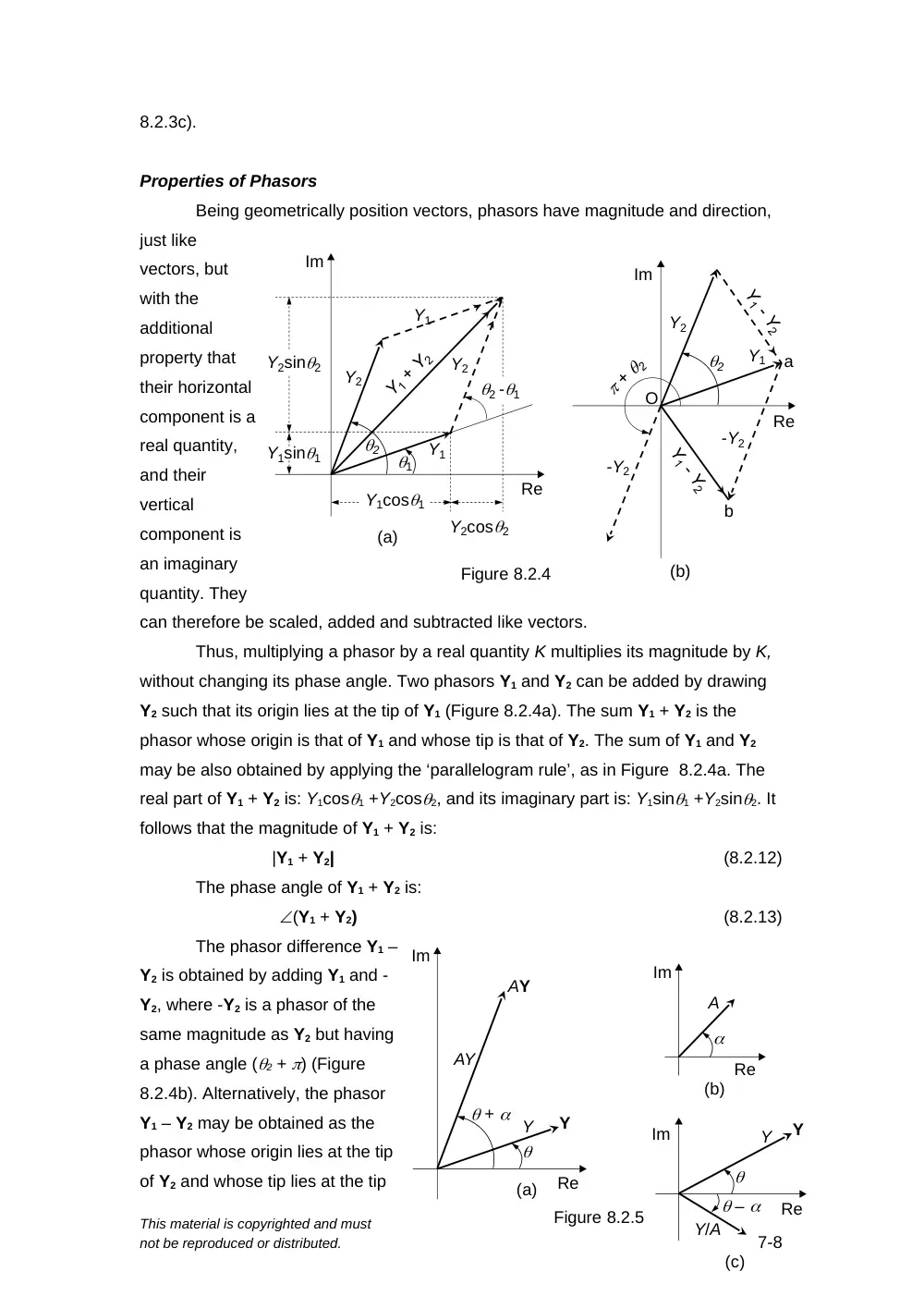
can therefore be scaled, added and subtracted like vectors.
Thus, multiplying a phasor by a real quantity K multiplies its magnitude by K,
without changing its phase angle. Two phasors Y1 and Y2 can be added by drawing
Y2 such that its origin lies at the tip of Y1 (Figure 8.2.4a). The sum Y1 + Y2 is the
phasor whose origin is that of Y1 and whose tip is that of Y2. The sum of Y1 and Y2
may be also obtained by applying the ‘parallelogram rule’, as in Figure 8.2.4a. The
real part of Y1 + Y2 is: Y1cos1 +Y2cos2, and its imaginary part is: Y1sin1 +Y2sin2. It
follows that the magnitude of Y1 + Y2 is:
|Y1 + Y2|
(8.2.12)
The phase angle of Y1 + Y2 is:
(Y1 + Y2)
(8.2.13)
The phasor difference Y1 –
Y2 is obtained by adding Y1 and -
Y2, where -Y2 is a phasor of the
same magnitude as Y2 but having
a phase angle (2 + ) (Figure
8.2.4b). Alternatively, the phasor
Y1 – Y2 may be obtained as the
phasor whose origin lies at the tip
of Y2 and whose tip lies at the tip
This material is copyrighted and must
not be reproduced or distributed.
7-8
Figure 8.2.4
(a)
(b)
1
2
2 -1
Y1
Y1
Y2
Y2
Y1cos1
Y2cos2
Y2sin2
Y1sin1
Y2
-Y2
Y1
-Y2
O
a
b
Im
Re
Im
Re
2
of Y1. Then: Y1 = Y2 + (Y1 – Y2).
A phasor Y (Figure 8.2.5a) may be multiplied by a complex quantity (Figure
8.2.5b):
(8.2.14)
The product is a phasor of magnitude AY and phase angle ( +) (Figure 8.25a).
A phasor Y may be divided by a complex quantity :
(8.2.15)
The quotient is a phasor of magnitude and phase angle ( –) (Figure 8.2.5c).
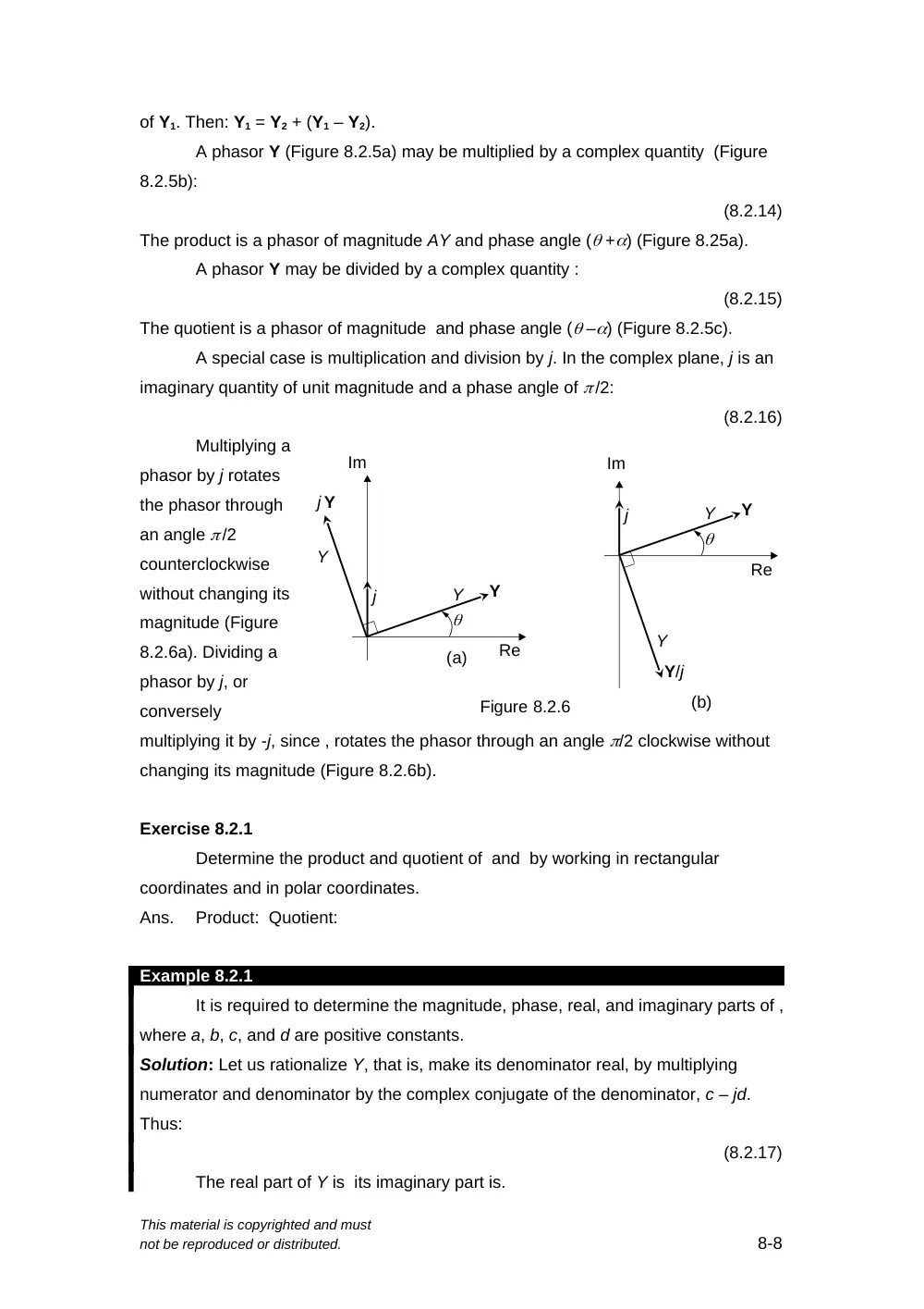
A special case is multiplication and division by j. In the complex plane, j is an
imaginary quantity of unit magnitude and a phase angle of /2:
(8.2.16)
Multiplying a
phasor by j rotates
the phasor through
an angle /2
counterclockwise
without changing its
magnitude (Figure
8.2.6a). Dividing a
phasor by j, or
conversely
multiplying it by -j, since , rotates the phasor through an angle /2 clockwise without
changing its magnitude (Figure 8.2.6b).
Exercise 8.2.1
Determine the product and quotient of and by working in rectangular
coordinates and in polar coordinates.
Ans.
Product: Quotient:
Example 8.2.1
It is required to determine the magnitude, phase, real, and imaginary parts of ,
where a, b, c, and d are positive constants.
Solution: Let us rationalize Y, that is, make its denominator real, by multiplying
numerator and denominator by the complex conjugate of the denominator, c – jd.
Thus:
(8.2.17)
The real part of Y is its imaginary part is.
This material is copyrighted and must
not be reproduced or distributed.
8-8
Y
Im
Re
Y
(a)
Figure 8.2.6
Y
j Y
j
Y
Im
Re
Y
(b)
j
Y
Y/j
The magnitude of Y may be obtained as the square root of the sum of the
squares of the real and imaginary parts. An easier way is to convert the numerator
and denominator to polar coordinates. Thus: .
The magnitude of Y is therefore . The phase angle of Y is (1 – 2) =
tan-1(b/a) – tan-1(d/c), that is, the phase angle is of the phase angle numerator minus
that of the denominator. The following should be noted:
i)
Whereas the magnitude of Y is the magnitude of the numerator divided by that of
the denominator, the real part of Y is not the real part of the numerator divided by
that of the denominator. Nor is the imaginary part of Y the imaginary part of the
numerator divided by that of the denominator.
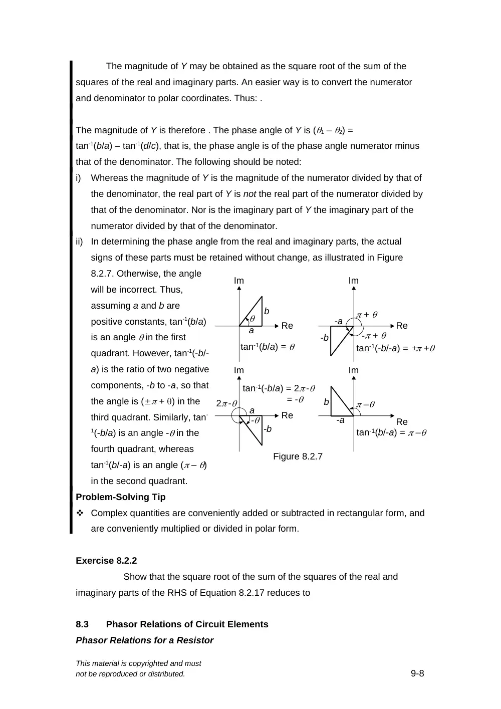
ii)
In determining the phase angle from the real and imaginary parts, the actual
signs of these parts must be retained without change, as illustrated in Figure
8.2.7. Otherwise, the angle
will be incorrect. Thus,
assuming a and b are
positive constants, tan-1(b/a)
is an angle in the first
quadrant. However, tan-1(-b/-
a) is the ratio of two negative
components, -b to -a, so that
the angle is ( + ) in the
third quadrant. Similarly, tan-
1(-b/a) is an angle - in the
fourth quadrant, whereas
tan-1(b/-a) is an angle ( – )
in the second quadrant.
Problem-Solving Tip
Complex quantities are conveniently added or subtracted in rectangular form, and
are conveniently multiplied or divided in polar form.
Exercise 8.2.2
Show that the square root of the sum of the squares of the real and
imaginary parts of the RHS of Equation 8.2.17 reduces to
8.3
Phasor Relations of Circuit Elements
Phasor Relations for a Resistor
This material is copyrighted and must
not be reproduced or distributed.
9-8
a
b
Im
Re
-a
-b
Im
Re
+
tan-1(b/a) =
a
-b
-
Im
Re
-a
b
Im
Re
–
tan-1(b/-a) = –
Figure 8.2.7
tan-1(-b/-a) = +
tan-1(-b/a) = 2 -
= -
2 -
- +
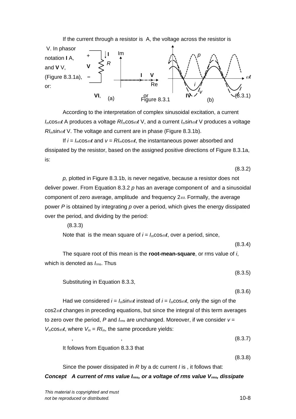
If the current through a resistor is A, the voltage across the resistor is
V. In phasor
notation I A,
and V V,
(Figure 8.3.1a),
or:
VI,
or
IV
(8.3.1)
According to the interpretation of complex sinusoidal excitation, a current
Imcost A produces a voltage RImcost V, and a current Imsint V produces a voltage
RImsint V. The voltage and current are in phase (Figure 8.3.1b).
If i = Imcost and v = RImcost, the instantaneous power absorbed and
dissipated by the resistor, based on the assigned positive directions of Figure 8.3.1a,
is:
(8.3.2)
p, plotted in Figure 8.3.1b, is never negative, because a resistor does not
deliver power. From Equation 8.3.2 p has an average component of and a sinusoidal
component of zero average, amplitude and frequency 2. Formally, the average
power P is obtained by integrating p over a period, which gives the energy dissipated
over the period, and dividing by the period:
(8.3.3)
Note that is the mean square of i = Imcost, over a period, since,
(8.3.4)
The square root of this mean is the root-mean-square, or rms value of i,
which is denoted as Irms. Thus
(8.3.5)
Substituting in Equation 8.3.3,
(8.3.6)
Had we considered i = Imsint instead of i = Imcost, only the sign of the
cos2t changes in preceding equations, but since the integral of this term averages
to zero over the period, P and Irms are unchanged. Moreover, if we consider v =
Vmcost, where Vm = RIm, the same procedure yields:
,
,
(8.3.7)
It follows from Equation 8.3.3 that
(8.3.8)
Since the power dissipated in R by a dc current I is , it follows that:
Concept
A current of rms value Irms, or a voltage of rms value Vrms, dissipate
This material is copyrighted and must
not be reproduced or distributed.
10-8
V
+
R
I
(a)
Figure 8.3.1
V
I
–
Im
Re
(b)
p
v
i
t
the same power in a given resistor as a dc current, or a dc voltage,
of the same value.
Using rms values of sinusoidal currents and voltages for power calculations
results in expressions of the same form as under dc conditions. The rms value is also
known as the effective value.
Phasor Relations for a Capacitor
If the current through a capacitor is A, the voltage across the capacitor is:
(8.3.9)
where K is the constant of integration that shifts the voltage in the vertical direction
and defines its average value. When a sinusoidal current of zero average is applied
to an uncharged capacitor, the resulting steady-state voltage is sinusoidal and of
zero average, so that K = 0.
In phasor notation, I A, and V V, or:
VI
or
IV
(8.3.10)
(Figure 8.3.2a). The
magnitude of V is
(1/C) times that of
I, and the phase
angle of V is -90
(Figure 8.3.2a).
According
to the interpretation of complex sinusoidal excitation, a current
Imcost A in a capacitor produces a voltage (Im/C)cos(t – /2) = (Im/C)sint
across the capacitor, and a current Imsint A produces a voltage (Im/C)sin(t – /2)
= (Im/C)cost. The voltage lags the current by 90, or the current leads the voltage
by 90 (Figure 8.3.2). This can be ascertained by comparing the time of occurrence of
the positive peaks of the waveforms of v and i in Figure 8.3.2b. Since the peak of v
occurs later in time than the peak of i by a quarter of a period, v lags i by 90.
The instantaneous power p absorbed by the capacitor is:
(8.3.11)
and,
(8.3.12)
p is plotted in Figure 8.3.2b. P = 0, because an ideal capacitor does not
dissipate power. The power absorbed (p > 0) and stored as electric energy during a
period is equal and opposite to the power delivered (p < 0), when the stored energy
is returned to the supply over the period.
This material is copyrighted and must
not be reproduced or distributed.
11-8
(a)
I
V
C
j
1
I
V
+
–
Figure 8.3.2
Im
Re
(b)
p
v
i
t
Phasor Relations for an Inductor
If the inductor current is A, the inductor voltage is:
(8.3.13)
In phasor notation, I A, and V V, or:
VI,
or
IV
(8.3.14)
The magnitude
of V is L times that of I,
and the phase angle of
V is 90 (Figure 8.3.3a).
According to
the interpretation of
complex sinusoidal
excitation, a current Imcost A in the inductor produces a voltage LImcos(t + 90) =
-LImsint across the inductor, and a current Imsint A produces a voltage LImsin(t
– 90) = -LImcost. The voltage leads the current by 90, or the current lags the
voltage by 90 (Figure 8.3.2(b)). This may be ascertained by comparing the time of
occurrence of the positive peaks of the waveforms of v and i.
Since the peak of v occurs earlier in time than the peak of i by a quarter of a period, v
leads i by 90.
The instantaneous power p absorbed by the inductor is:
(8.3.15)
and,
(8.3.16)
p, plotted in Figure 8.3.3b. P = 0, because an ideal inductor does not
dissipate power. The power absorbed (p > 0) and stored as magnetic energy during
a period is equal and opposite to the power delivered (p < 0), when the stored energy
is returned to the supply over the period.
From the preceding discussion, the v-i relations of capacitors and inductors in
the time domain and in phasor notation are as follows:
For a capacitor
,
and
(8.3.17)
For an inductor
,
and
(8.3.18)
It is seen that:
Concept
In phasor notation, differentiation in time is expressed as
multiplication by j, and integration in time is expressed as division
by j. Thus, differential and integral relations are transformed to
algebraic relations in j for steady-state sinusoidal analysis ONLY.
This concept in fact underlies the usefulness of phasor notation for steady-
state sinusoidal analysis.
This material is copyrighted and must
not be reproduced or distributed.
12-8
jL
(a)
I
V
V
+
I
–
Figure 8.3.3
Im
Re
(b)
p
v
i
t
Another important observation is that v and i are in phase for an ideal resistor
but are in phase quadrature for ideal capacitors and inductors. This is because an
ideal resistor only dissipates power. It does not store energy that must be returned
later to the supply. If no power is delivered by an ideal resistor, p is never negative,
which means that v and i are in phase.
On the other hand, ideal capacitors and inductors do not dissipate power,
which means that the average power P over a period is zero. For this to be the case,
v and i must be in phase quadrature, which means that one is a cosine function and
the other is a sine function, so that their product averages to zero over a period.
Concept
The sinusoidal voltage and current for an ideal resistor are in phase
because such a resistor is purely dissipative. They are in phase
quadrature for ideal energy storage elements because these
elements are nondissipative.
Exercise 8.3.1
The voltage applied to a resistor is peak, the frequency being 50 Hz.
Determine: (a) the expression for the current in the time
domain, assuming the voltage is a cosine function; and (b) the power dissipated in
the resistor.
Ans.
(a) ; (b) 320 W.
Exercise 8.3.2
The current through a series combination of a 10 mH inductor and a
capacitor is rms. Assuming the frequency is 200 Hz and the time variation is a sine
function, determine the expression in the time domain of the voltage across: (a)
inductor; and (b) the capacitor.
Ans.
(a) 60sin(400t + 15) mV rms; (b) (750/) sin(400t –165) mV rms
8.4
Impedance and Reactance
Let V = be a voltage phasor and I = be a related
current phasor, representing, for example, the voltage and
current between any two nodes in a circuit (Figure 8.4.1), and let
.
Then:
Definition
Impedance Z is the ratio of the voltage phasor
Vm v between any two nodes in a circuit to the current phasor
Im I flowing between these nodes in the direction of a voltage
drop.
This material is copyrighted and must
not be reproduced or distributed.
13-8
Figure 8.4.1
V
+
I
–
= Z
(8.4.1)
(Figure 8.4.2a). When V is in volts and I is in amperes Z is in ohms. Since Z is in
general complex, it can be expressed as:
Z = R + jX
(8.4.2)
(Figure 8.4.2b). It should be emphasized that
although Z is in general complex, it is not a
phasor, because it is not a complex sinusoidal
function of time in which the time variation has
been suppressed. In fact, the exponential time
variation cancels out in Equation 8.4.1.
In the case of an ideal resistor, V and I are
in phase (Equation 8.3.1), which means that
Z is real and equal to R. It follows that R in Equation 8.4.2 is the usual resistance that
we have considered in previous chapters, and that for an ideal resistor, X = 0.
X, the imaginary part of Z, is the reactance and its unit is the ohm, just like
resistance and impedance.
For an ideal capacitor, Z = so that X = . For an ideal inductor, Equation 8.3.9
gives , so that . For both ideal energy storage elements, R = 0, since these elements
are nondissipative.
It should be emphasized that when X = 0, V and I are in phase. When X 0,
Z is complex and V and I are out of phase. Hence:
Concept
In a purely resistive circuit, all sinusoidal voltages and currents are
in phase and their magnitudes do not depend on frequency. Energy-
storage storage elements possess reactance, which causes
frequency-dependent phase differences between sinusoidal voltages
and currents in the circuit and, in addition, makes the amplitudes of
these sinusoidal voltages and currents depend on frequency.
The following should be noted concerning reactance:
1.
In any expression that involves impedance, reactance is always multiplied by j.
For an ideal capacitor, X = -1/C and Z = -j/C. For an ideal inductor, X = L and
Z = jL.
2.
Since j appears in the V-I relations as a result of differentiating or integrating
expressions involving e
jt, j is always associated with in the expression for
impedance. Hence, reactance is always a function of frequency.
The reciprocal of impedance is the admittance Y:
(8.4.3)
This material is copyrighted and must
not be reproduced or distributed.
14-8
V
R
X
(a)
(b)
Figure 8.4.2
Im
Vm
I
i
v
jB
G
Y
Z
1
where B is the susceptance. Like G, B and Y are in siemens.
For an ideal resistor, I/V = G (Equation 8.3.1), so that B = 0, and G is the
usual conductance. For an ideal capacitor, Y = I/V = jC (Equation 8.3.7), so that G =
0 and B = jC. For an ideal inductor, Y = I/V = 1/jL =`-1/ (Equation 8.3.9), so that G
= 0, and B = -1/L. Table 8.4.1 lists the circuit properties of the three circuit
elements. It is seen that under dc conditions = 0, which makes the reactance of a
capacitor infinite and its susceptance zero. This means that when the voltage across
the capacitor is dc, the current is zero. The capacitor behaves as an open circuit, as
argued in Section 7.1, Chapter 7. Similarly, when = 0, the reactance of an inductor
is zero and its
susceptance is
infinite. This
means that when
the inductor
current is dc, the
voltage across
the inductor is
zero. The
inductor behaves as a short circuit, as argued in Section 7.2, Chapter 7.
Note that whereas G = 1/R for an ideal resistor, B = -1/X for an ideal capacitor
or inductor. This is because conversion from reactance to susceptance must proceed
through impedance and admittance, which introduces a minus sign in the reciprocal
of the imaginary component. Thus, Z = jX, Y = 1/Z = 1/jX = -j/X. But Y = jB, so that B
= -1/X.
Exercise 8.4.1
Find the reactance and susceptance of (a) the inductor and (b) the capacitor
of Exercise 8.3.2.
Ans.
(a) Inductor: , S; (b) Capacitor: -50/ , /50 S.
Example 8.4.1
Given an impedance Zs = Rs
+ jLs, represented as Rs in series
with Ls. It is required to determine
Rp and Lp of the equivalent parallel
combination (Figure 8.4.3).
Solution: Since the two circuits are
This material is copyrighted and must
not be reproduced or distributed.
15-8
Rs
Ls
Rp
Lp
(a)
(b)
Figure 8.4.3
Zs
Zp
a
b
a
b
Table 8.4.1
Circuit Properties of Circuit Elements
Circuit Property
Resistor
Inductor
Capacitor
Reactance (X)
0
L
C
1
Impedance (Z)
R
jL
C
j
j C
1
Susceptance (B)
0
L
1
C
Admittance (Y)
G =
R
1
L
j
j L
1
jC
equivalent between terminals ‘ab’, they must have the same V and I at these
terminals, so that the ratio V/I is the same. This means that Zs = Zp = 1/Yp. It follows
that: . Rationalizing this fraction by multiplying the numerator and denominator by the
complex conjugate of the denominator, so as to make the denominator real,
(8.4.4)
Equating real and imaginary parts,
and
(8.4.5)
From Table 8.4.1, Gp = 1/Rp and Bp = -1/Lp. It follows that:
(8.4.6)