
EECE 210 Chapter 2, Fall 2012
American University of Beirut · Electric Circuits · 14 pages
Showing the first 10 of 14 pages. Download the PDF to see all of it.
More EECE 210 files
- Chapter Uploading Chapter 08 Sinusoidal Steady · Spring 2015ChapterView
- Homework All Chapters · Fall 2015ChapterView
- Chapter 1 · Fall 2012ChapterView
- Chapter 3 · Fall 2012ChapterView
- Chapter 4 · Fall 2012ChapterView
- Chapter 5 · Fall 2012ChapterView
- Chapter 6 · Fall 2012ChapterView
- Chapter 7 · Fall 2012ChapterView
Show the text of this chapter
Chapter 2
Basic Circuit Connections and Laws
2.1
Circuit Terminology
Node: junction of two or more circuit elements.
Essential node: junction of three or more circuit elements.
Path: set of one or more adjoining circuit elements that may be traversed in
succession without passing through the same node more than once. A path
generally has an initial node at its beginning and a final node at its end.
If the initial and final nodes are the same, the path is closed and becomes a loop.
Mesh: a loop that does not enclose any other loop.
Branch: path that connects two nodes.
Essential branch: branch that connects two essential nodes without passing
through an essential node.
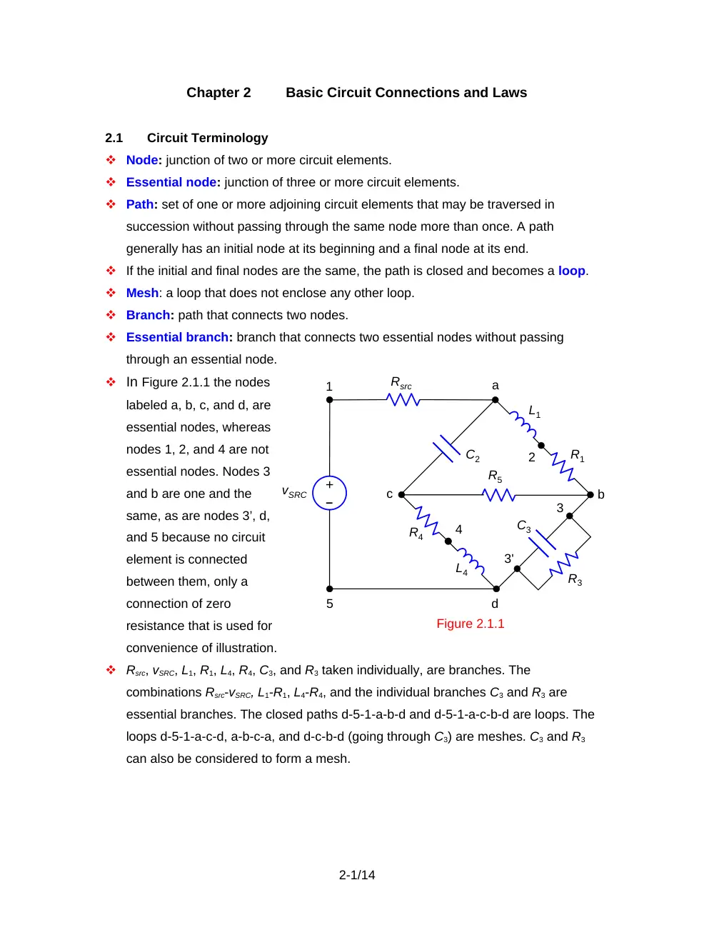
In Figure 2.1.1 the nodes
labeled a, b, c, and d, are
essential nodes, whereas
nodes 1, 2, and 4 are not
essential nodes. Nodes 3
and b are one and the
same, as are nodes 3’, d,
and 5 because no circuit
element is connected
between them, only a
connection of zero
resistance that is used for
convenience of illustration.
Rsrc, vSRC, L1, R1, L4, R4, C3, and R3 taken individually, are branches. The
combinations Rsrc-vSRC, L1-R1, L4-R4, and the individual branches C3 and R3 are
essential branches. The closed paths d-5-1-a-b-d and d-5-1-a-c-b-d are loops. The
loops d-5-1-a-c-d, a-b-c-a, and d-c-b-d (going through C3) are meshes. C3 and R3
can also be considered to form a mesh.
2-1/14
Figure 2.1.1
L1
vSRC
a
b
c
d
1
2
3'
4
R1
R4
L4
R3
C3
R5
C2
–
+
Rsrc
5
3
2.2
Kirchhoff’s Laws
Kirchhoff’s Current Law
Statement
At any instant of time, the sum of currents entering a node is equal
to the sum of currents leaving the node.
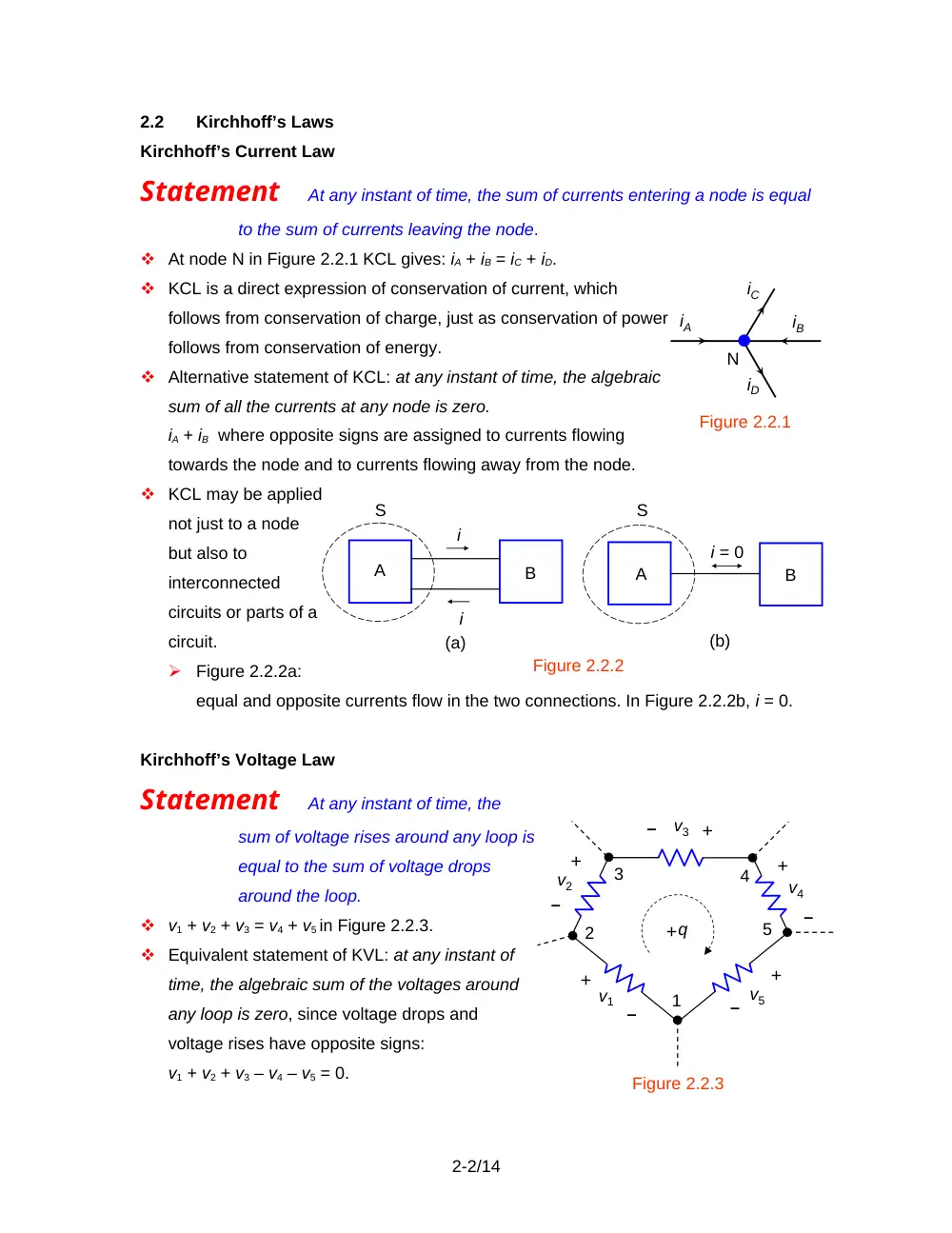
At node N in Figure 2.2.1 KCL gives: iA + iB = iC + iD.
KCL is a direct expression of conservation of current, which
follows from conservation of charge, just as conservation of power
follows from conservation of energy.
Alternative statement of KCL: at any instant of time, the algebraic
sum of all the currents at any node is zero.
iA + iB where opposite signs are assigned to currents flowing
towards the node and to currents flowing away from the node.
KCL may be applied
not just to a node
but also to
interconnected
circuits or parts of a
circuit.
Figure 2.2.2a:
equal and opposite currents flow in the two connections. In Figure 2.2.2b, i = 0.
Kirchhoff’s Voltage Law
Statement
At any instant of time, the
sum of voltage rises around any loop is
equal to the sum of voltage drops
around the loop.
v1 + v2 + v3 = v4 + v5 in Figure 2.2.3.
Equivalent statement of KVL: at any instant of
time, the algebraic sum of the voltages around
any loop is zero, since voltage drops and
voltage rises have opposite signs:
v1 + v2 + v3 – v4 – v5 = 0.
2-2/14
Figure 2.2.1
N
iA
iC
iB
iD
A
B
i
i
(a)
A
i = 0
B
(b)
Figure 2.2.2
S
S
Figure 2.2.3
v1
v5
v2
v4
v3
q
+
+
+
+
+
–
–
–
–
–
+
1
2
3
4
5
Concept KCL and KVL together are an expression of conservation of energy.
In taking a charge +q clockwise around the loop, the work done on the charge is q(v1
+ v2 + v3). But the charge can do more work, q(v4 + v5), if (v1 + v2 + v3) < (v4 + v5),
which violates conservation of energy. Taking the charge +q around a loop, which
necessarily involves passing through nodes or essentials nodes between the circuit
elements, implies that the charge +q is conserved at these nodes, that is, KCL
applies.
2.3
Voltage Division and Series Connection of Resistors
Definition
In a series connection of elements, the same current flows
through all the elements.
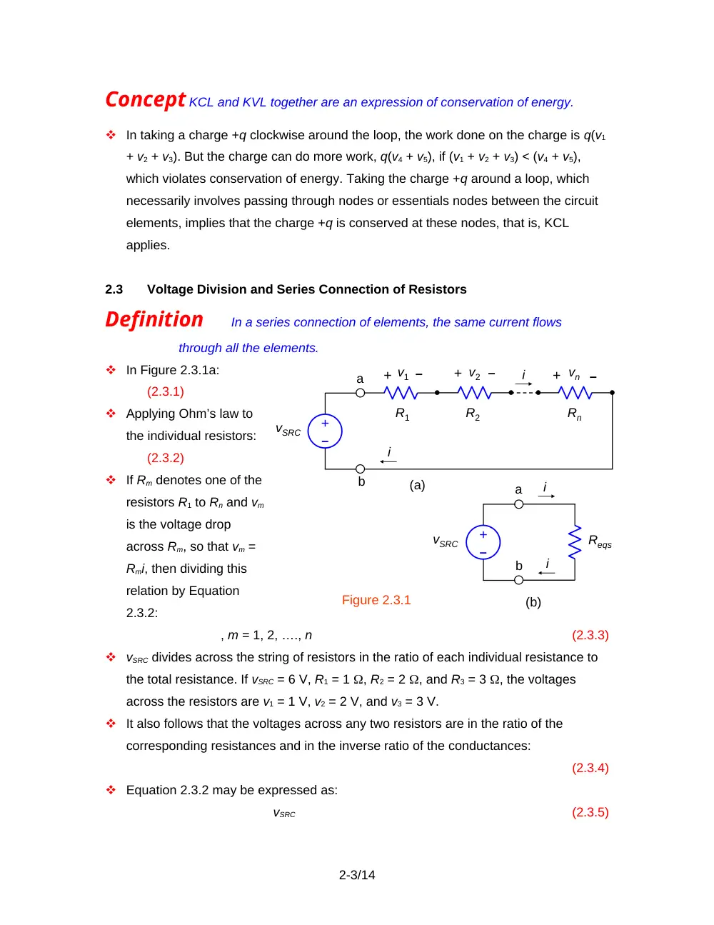
In Figure 2.3.1a:
(2.3.1)
Applying Ohm’s law to
the individual resistors:
(2.3.2)
If Rm denotes one of the
resistors R1 to Rn and vm
is the voltage drop
across Rm, so that vm =
Rmi, then dividing this
relation by Equation
2.3.2:
, m = 1, 2, …., n
(2.3.3)
vSRC divides across the string of resistors in the ratio of each individual resistance to
the total resistance. If vSRC = 6 V, R1 = 1 , R2 = 2 , and R3 = 3 , the voltages
across the resistors are v1 = 1 V, v2 = 2 V, and v3 = 3 V.
It also follows that the voltages across any two resistors are in the ratio of the
corresponding resistances and in the inverse ratio of the conductances:
(2.3.4)
Equation 2.3.2 may be expressed as:
vSRC
(2.3.5)
2-3/14
Figure 2.3.1
i
Reqs
i
R1
R2
Rn
+ v2
–
+ v1
–
+ vn
–
i
i
a
a
b
b
(a)
(b)
vSRC
–
+
–
+
vSRC
An equivalent series resistor Reqs is defined such that if vSRC is applied across
Reqs, the resulting current is i (Figure 2.3.1b):
(2.3.6)
Comparing Equations (2.3.5) and (2.3.6), it follows that:
(2.3.7)
In the case of the 1, 2, and 3 resistors connected in series, Reqs = 6 .
Because of the summation of positive quantities in Equation 2.3.7, Reqs is larger
than the largest of the individual resistances.
If all the n resistances are equal, Reqs = nR.
If the resistors in Figure 2.3.1a are represented by their conductances, then every
resistance in Equation 2.3.7 is replaced by the reciprocal of its reciprocal
conductance, which leaves the quantity unchanged. Thus:
(2.3.8)
The conductances of the three series-connected 1, 2, and 3 resistors are,
respectively, 1, , and S. The sum of their reciprocals is 6 S-1, and S, which is of
course the reciprocal of Reqs.
Summary
In a series connection of resistors, the resistances, or the
reciprocals of the
conductances, add.
2.4
Current Division and Parallel
Connection of Resistors
Definition In a parallel
connection of elements, the same
voltage is applied across all the
elements.
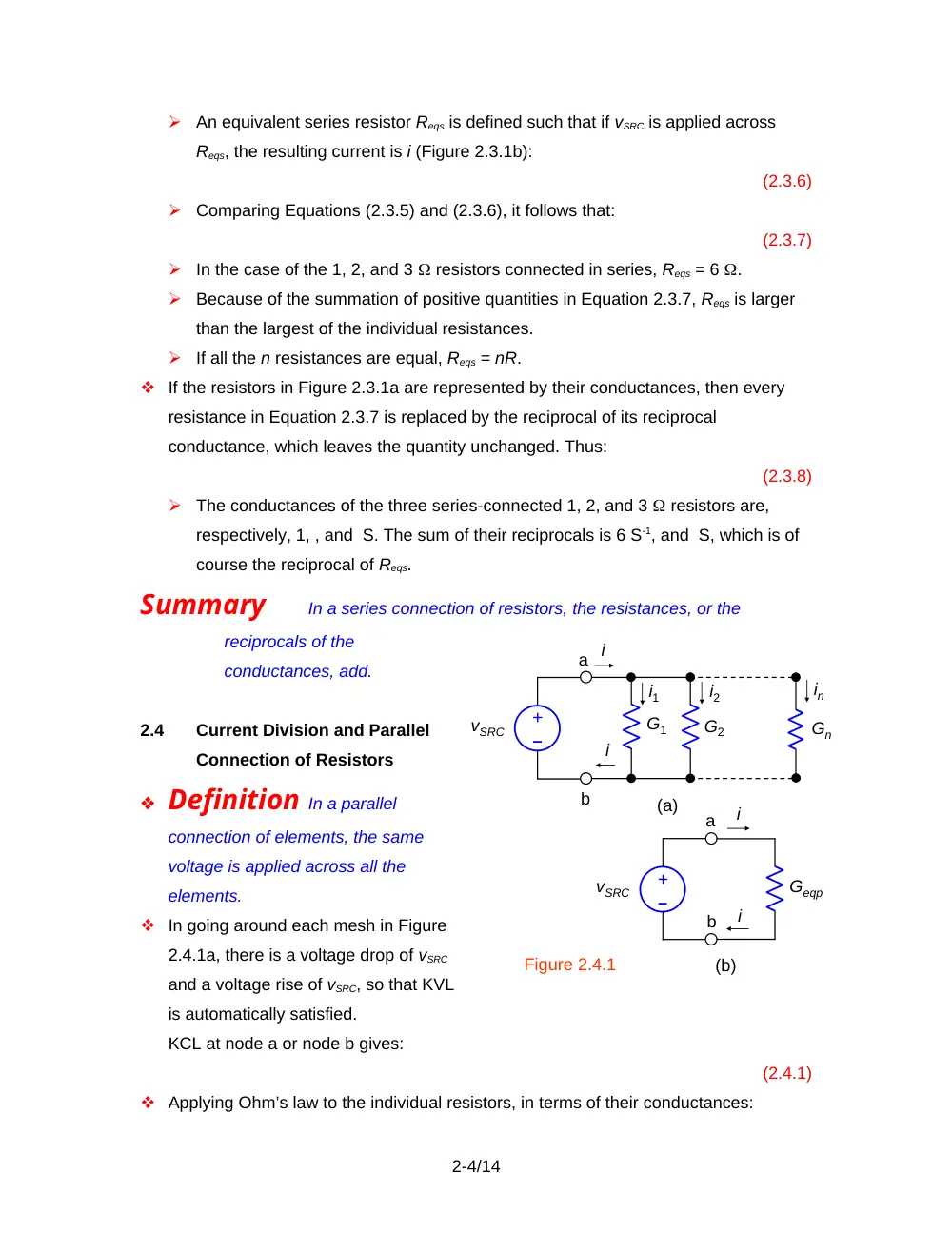
In going around each mesh in Figure
2.4.1a, there is a voltage drop of vSRC
and a voltage rise of vSRC, so that KVL
is automatically satisfied.
KCL at node a or node b gives:
(2.4.1)
Applying Ohm’s law to the individual resistors, in terms of their conductances:
2-4/14
Figure 2.4.1
i
i
i1
i
i
i2
in
Geqp
G1
G2
Gn
(a)
(b)
a
a
b
b
vSRC
–
+
vSRC
–
+
i1
i
i
i2
R1
R2
vSRC
–
+
Figure 2.4.2
(2.4.2)
If Gm denotes one of the conductances G1 to Gn, and im is the current through Gm, so
that im = GmvSRC, then dividing this relation by Equation 2.4.2:
, m = 1, 2, …., n
(2.4.3)
i divides between the paralleled resistors in the ratio of each individual conductance
to the total conductance. Moreover, the currents through any two resistors are in the
ratio of the corresponding conductances, or the inverse ratio of the resistances:
(2.4.4)
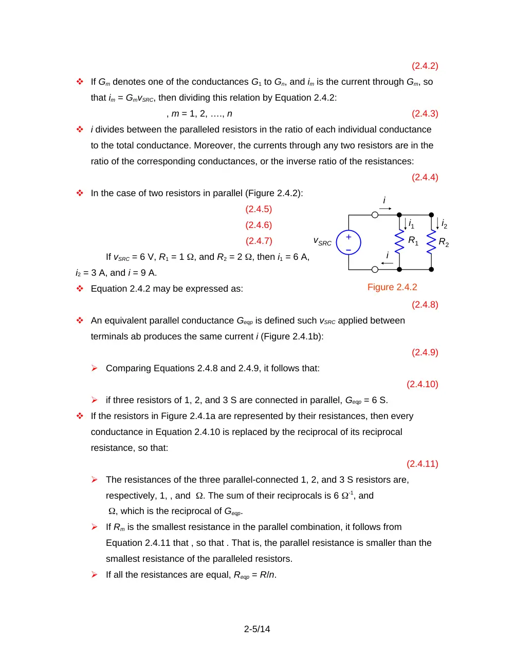
In the case of two resistors in parallel (Figure 2.4.2):
(2.4.5)
(2.4.6)
(2.4.7)
If vSRC = 6 V, R1 = 1 , and R2 = 2 , then i1 = 6 A,
i2 = 3 A, and i = 9 A.
Equation 2.4.2 may be expressed as:
(2.4.8)
An equivalent parallel conductance Geqp is defined such vSRC applied between
terminals ab produces the same current i (Figure 2.4.1b):
(2.4.9)
Comparing Equations 2.4.8 and 2.4.9, it follows that:
(2.4.10)
if three resistors of 1, 2, and 3 S are connected in parallel, Geqp = 6 S.
If the resistors in Figure 2.4.1a are represented by their resistances, then every
conductance in Equation 2.4.10 is replaced by the reciprocal of its reciprocal
resistance, so that:
(2.4.11)
The resistances of the three parallel-connected 1, 2, and 3 S resistors are,
respectively, 1, , and . The sum of their reciprocals is 6 -1, and
, which is the reciprocal of Geqp.
If Rm is the smallest resistance in the parallel combination, it follows from
Equation 2.4.11 that , so that . That is, the parallel resistance is smaller than the
smallest resistance of the paralleled resistors.
If all the resistances are equal, Reqp = R/n.
2-5/14
Summary
In a parallel connection of resistors, the conductances, or the
reciprocals of the resistances, add.
According to Equation 2.4.11, Reqp is the product of the n resistances divided by the
sum of their products (n – 1) at a time. In the case of three resistors in parallel:
(2.4.12)
For two resistors:
(2.4.13)
Example 2.4.1
Resistivity
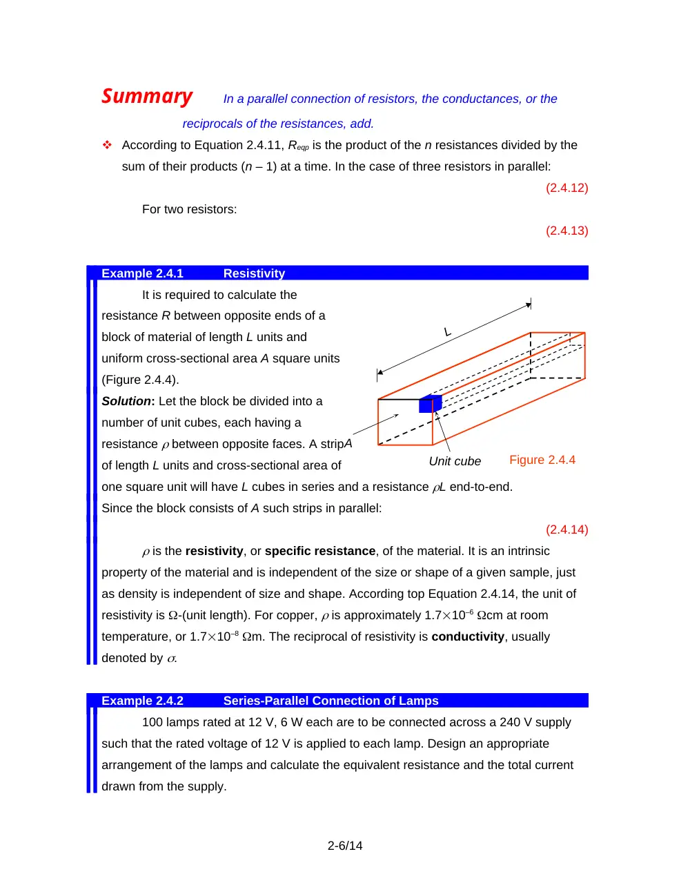
It is required to calculate the
resistance R between opposite ends of a
block of material of length L units and
uniform cross-sectional area A square units
(Figure 2.4.4).
Solution: Let the block be divided into a
number of unit cubes, each having a
resistance between opposite faces. A strip
of length L units and cross-sectional area of
one square unit will have L cubes in series and a resistance L end-to-end.
Since the block consists of A such strips in parallel:
(2.4.14)
is the resistivity, or specific resistance, of the material. It is an intrinsic
property of the material and is independent of the size or shape of a given sample, just
as density is independent of size and shape. According top Equation 2.4.14, the unit of
resistivity is -(unit length). For copper, is approximately 1.710–6 cm at room
temperature, or 1.710–8 m. The reciprocal of resistivity is conductivity, usually
denoted by .
Example 2.4.2
Series-Parallel Connection of Lamps
100 lamps rated at 12 V, 6 W each are to be connected across a 240 V supply
such that the rated voltage of 12 V is applied to each lamp. Design an appropriate
arrangement of the lamps and calculate the equivalent resistance and the total current
drawn from the supply.
2-6/14
L
Figure 2.4.4
A
Unit cube
Solution: Since = 20, then 20 lamps may be connected in series across the supply. The
voltage across each lamp will be the rated voltage of 12 V, assuming the lamp
resistances are all equal. To accommodate 100 lamps, 5 such series combinations will
have to be paralleled across the supply. The resistance of each lamp is at the normal
operating temperature. The equivalent series resistance of 20 lamps is 2420 = 480 .
The equivalent parallel resistance of five of these series combinations is . The lamp
current at 12 V is A, which is also the current in each series combination. The total
current drawn from the supply is 50.5 = 2.5 A.
As a check, we may calculate P, the total power supplied. From the total current,
P = 2402.5 = 600 W. From the total resistance: . From the total number of lamps and
their individual ratings: P = 1006 W = 600 W.
2.5 -Y Transformation
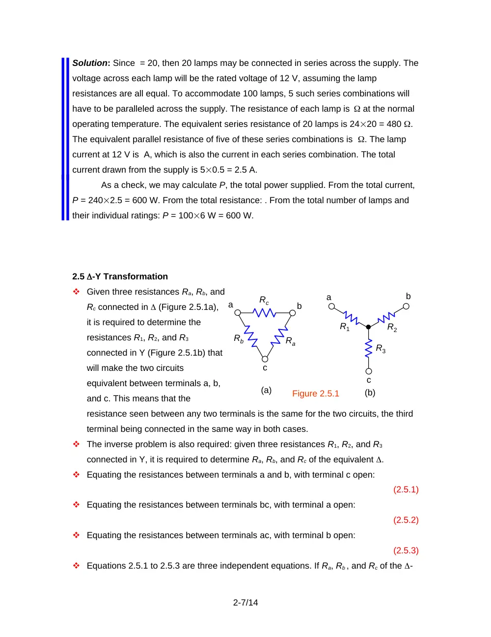
Given three resistances Ra, Rb, and
Rc connected in (Figure 2.5.1a),
it is required to determine the
resistances R1, R2, and R3
connected in Y (Figure 2.5.1b) that
will make the two circuits
equivalent between terminals a, b,
and c. This means that the
resistance seen between any two terminals is the same for the two circuits, the third
terminal being connected in the same way in both cases.
The inverse problem is also required: given three resistances R1, R2, and R3
connected in Y, it is required to determine Ra, Rb, and Rc of the equivalent .
Equating the resistances between terminals a and b, with terminal c open:
(2.5.1)
Equating the resistances between terminals bc, with terminal a open:
(2.5.2)
Equating the resistances between terminals ac, with terminal b open:
(2.5.3)
Equations 2.5.1 to 2.5.3 are three independent equations. If Ra, Rb , and Rc of the -
2-7/14
Figure 2.5.1
Ra
Rb
Rc
a
b
c
c
a
b
R1
R2
R3
(a)
(b)
circuit are given, these equations can be solved for R1, R2, and R3 of the equivalent
Y-circuit:
(2.5.4)
(2.5.5)
(2.5.6)
Conversely, if the resistances R1, R2 , and R3 of the Y-circuit are given, Equations
2.5.1 to 2.5.3 can be solved for Ra, Rb , and Rc of the equivalent -circuit:
(2.5.7)
(2.5.8)
(2.5.9)
To help remember the above relations, the two equivalent circuits are superimposed
(Figure 2.5.2). Each Y-resistance is the product of
the -resistances on either side of it divided by the
sum of the three -resistances. Conversely, each
-resistance is the product of Y-resistances two at
a time divided by the Y-resistance that is opposite
the given -resistance.
When the three resistances in either configuration
are equal, the above relations reduce to:
R = 3RY,
and
RY = R / 3
(2.5.10)
Example 2.5.1
-Y Transformation
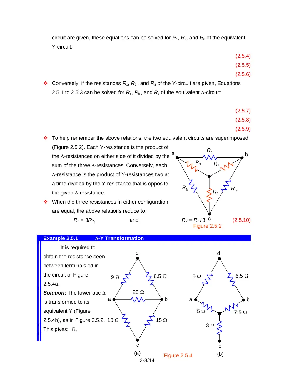
It is required to
obtain the resistance seen
between terminals cd in
the circuit of Figure
2.5.4a.
Solution: The lower abc
is transformed to its
equivalent Y (Figure
2.5.4b), as in Figure 2.5.2.
This gives: ,
2-8/14
Figure 2.5.4
a
a
b
b
c
c
d
d
10
15
25
5
3
7.5
9
6.5
(a)
(b)
9
6.5
c
R1
R2
a
b
Rc
Ra
Rb
Figure 2.5.2
R3
, and . The 5 resistance is then added to the 9 to give 14 , and the 7.5
resistance is added to the 6.5 to give 14 . The two 14 resistors in parallel give 7 ,
which is added to the 3 to give 10 between terminals cd.
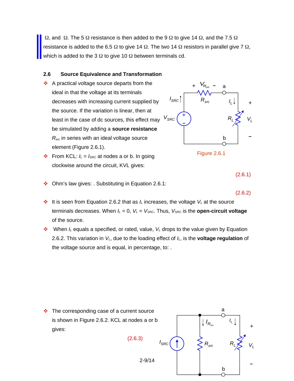
2.6
Source Equivalence and Transformation
A practical voltage source departs from the
ideal in that the voltage at its terminals
decreases with increasing current supplied by
the source. If the variation is linear, then at
least in the case of dc sources, this effect may
be simulated by adding a source resistance
Rsrc in series with an ideal voltage source
element (Figure 2.6.1).
From KCL: IL = ISRC at nodes a or b. In going
clockwise around the circuit, KVL gives:
(2.6.1)
Ohm’s law gives: . Substituting in Equation 2.6.1:
(2.6.2)
It is seen from Equation 2.6.2 that as IL increases, the voltage VL at the source
terminals decreases. When IL = 0, VL = VSRC. Thus, VSRC is the open-circuit voltage
of the source.
When IL equals a specified, or rated, value, VL drops to the value given by Equation
2.6.2. This variation in VL, due to the loading effect of IL, is the voltage regulation of
the voltage source and is equal, in percentage, to: .
The corresponding case of a current source
is shown in Figure 2.6.2. KCL at nodes a or b
gives:
(2.6.3)
2-9/14
Rsrc
VSRC
+
ISRC
a
b
+
IL
VL
RL
Figure 2.6.1
–
–
–
+
Rsrc
V
ISRC
Rsrc
VL
b
a
+
IL
RL
–
RI src
KVL is automatically satisfied since the same voltage VL is across all the circuit
elements.
Multiplying both sides of Equation 2.6.3 by Rsrc and substituting :
VL = RsrcISRC – RsrcIL
(2.6.4)
When VL = 0, IL = ISRC. As VL increases, more of ISRC is diverted to Rsrc, so IL
decreases. Current regulation occurs, analogous to voltage regulation in a voltage
source.
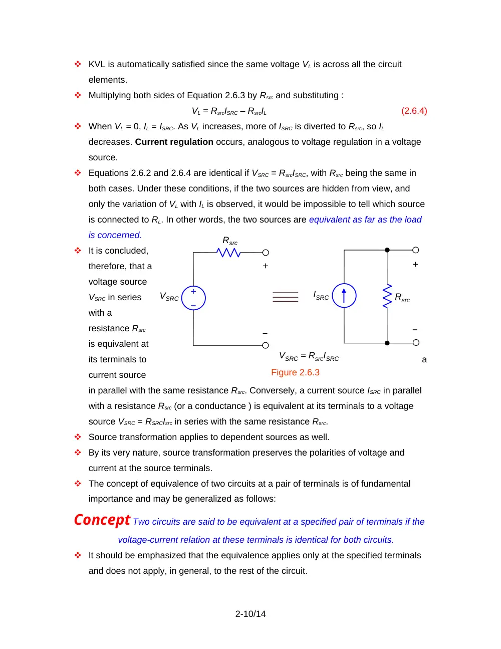
Equations 2.6.2 and 2.6.4 are identical if VSRC = RsrcISRC, with Rsrc being the same in
both cases. Under these conditions, if the two sources are hidden from view, and
only the variation of VL with IL is observed, it would be impossible to tell which source
is connected to RL. In other words, the two sources are equivalent as far as the load
is concerned.
It is concluded,
therefore, that a
voltage source
VSRC in series
with a
resistance Rsrc
is equivalent at
its terminals to
a
current source
in parallel with the same resistance Rsrc. Conversely, a current source ISRC in parallel
with a resistance Rsrc (or a conductance ) is equivalent at its terminals to a voltage
source VSRC = RSRCIsrc in series with the same resistance Rsrc.
Source transformation applies to dependent sources as well.
By its very nature, source transformation preserves the polarities of voltage and
current at the source terminals.
The concept of equivalence of two circuits at a pair of terminals is of fundamental
importance and may be generalized as follows:
Concept Two circuits are said to be equivalent at a specified pair of terminals if the
voltage-current relation at these terminals is identical for both circuits.
It should be emphasized that the equivalence applies only at the specified terminals
and does not apply, in general, to the rest of the circuit.
2-10/14
VSRC
Rsrc
ISRC
Figure 2.6.3
Rsrc
–
+
VSRC = RsrcISRC
+
–
+
–
Example 2.6.1
Equivalent Sources
Given a
voltage source
having an open-
circuit voltage of 12
V and a source
resistance of 0.5
(Figure 2.6.4a). It is
required to derive
the equivalent current source.
Solution: According to the above discussion, the equivalent current source has a source
current of A and a source resistance of 0.5 (Figure 2.6.4b).
If both sources are connected to a 5.5 load, for example, IL for the voltage
source case is, from Figure 2.6.4 (a): IL = A, and VL = 25.5 = 11 V. In the case of the
current source (Figure 2.6.4b), the resistance of the parallel combination is ; V, as in
the case of the voltage source. However, the power delivered by the voltage source is
whereas the power delivered by the current source is 1124 = 264 W. The power
absorbed by Rsrc is W in the case of the voltage source and W in the case of the
current source. Moreover, the current in the 0.5 resistor is not the same in both cases.
It is 2A in (a) and 22 A in (b).
Concept The ideal termination for a voltage source is an open circuit, whereas the
ideal termination for a current source is a short circuit.
This is because the full voltage VSRC is available at the terminals of a voltage source
only when IL = 0, that is, when the source terminals are open circuited. Similarly, the
full current ISRC is available at the terminals of a current source only when VL = 0, that
is, when the source terminals are short circuited.
2.7
Reduced-Voltage Supply
The simple resistive voltage divider is often used to supply a load at a reduced
voltage.
The basic circuit is shown in Figure 2.7.1.
2-11/14
(a)
0.5
5.5
(b)
12 V
IL
24 A
IL
Figure 2.6.4
–
+
+
VL
–
5.5
0.5
+
VL
–
VSRC
R1
+
I1
+
V1
I2
IL
–
+
–
Figure 2.7.2
SRC
RV
R
R
2
1
2
R1||R2
–
+
+
–
VL
Load
Normally, VSRC is given together with the nominal load voltage VL and a range of
variation of the load current IL. It is desired to determine R1 and R2 such that the
variation in VL remains within specified limits as IL changes over the given range.
From KCL at either essential node:
(2.7.1)
Applying KVL clockwise around the mesh composed of VSRC, R1, and R2:
(2.7.2)
From Ohm’s law:
and
(2.7.3)
I1, I2 and V1 may be eliminated from the above four equations to give:
(2.7.4)
(2.7.5)
where is the parallel resistance of R1 and R2.
Comparing Equation 2.7.5 with Equation 2.6.2, it
follows that the voltage divider
appears to the load as a source of
open-circuit voltage , when IL = 0, and
source resistance (Figure 2.7.2).
Given VSRC, VL, and IL, Equation 2.7.5
provides a relation between R1 and R2,
but is not sufficient for uniquely
determining their values. The additional information needed for this purpose comes
from specifying the voltage variation VL = VL2 – VL1 forIL = IL2 – IL1. Substituting first
VL1 and IL1, in Equation 2.7.5, then VL2 and IL2, and subtracting, eliminates the term in
VSRC and gives:
(2.7.6)
The interpretation of Equation 2.7.6 is that when is constant and IL changes by IL,
VL is due to the voltage drop in, which is ()IL. The minus sign in Equation 2.7.6
signifies that VL decreases with IL.
It is desirable in practice to have a small VL for a given IL, which means that should
be small. It is seen from Equation 2.7.5 that this makes small compared to the first
term, , which means that . Under these conditions, is fixed for given VSRC and VL.
To reduce while keeping constant, both R1 and R2 should be reduced. But reducing
2-12/14
R1 and R2, increases the current drain from the supply, and generally increases the
power dissipated in the voltage divider. This is undesirable, particularly in battery-
operated equipment. Hence a tradeoff must be made in the design of the resistive
voltage divider between good voltage regulation, that is, a small VL, on the one
hand, and current drain from the supply and power dissipation in R1 and R2 on the
other hand. For these reasons, the resistive voltage divider is impractical where there
is a substantial variation in load current.
Design Example 2.7.1
Voltage Regulation and Power Dissipation in a Voltage
Divider
A 3 V, 0.1 A dc load is to be supplied from a 12 V dc supply. The load current
may vary by 20% of its nominal value of 0.1 A. The corresponding variation in the load
voltage should not exceed 5% of the nominal value of 3 V. It is required to determine
suitable values of R1 and R2.
Solution: According to Equation 2.7.5, IL has its largest value when VL has its smallest
value, and conversely. At IL = 0.80.1 = 0.08 A, VL = 1.053 = 3.15 V, and at IL =
1.20.1 = 0.12 A, VL = 0.953 = 2.85 V. Substituting these values in Equation 2.7.5
gives two relations between R1 and R2:
,
and
From these, R1 = 24 and R2 =10.9 . Note that an easy way to solve these equations
is to consider as one variable and as another variable.
Let us calculate P, the total power dissipated in R1 and R2 under these
conditions. With reference to Figure 2.7.1, . When VL = 3.15 V, P = 4.17 W, and when VL
= 2.85 V, P = 4.23 W. P may not seem like an excessive amount of power. But if it is
noted that the power consumed by the load does not exceed 0.34 W, when VL = 2.85 V
and IL = 0.12 A, it is seen that of the power supplied by VSRC goes to the load under
these conditions, the rest is dissipated in R1 and R2. The power efficiency is therefore
quite poor.
Suppose that in order to dissipate less power in R1 and R2, R1 is increased by a
factor of 3 to 72 . From Equation 2.7.5: , which gives R2 = 120 . With these values of
R1 and R2, VL = 3 V when IL = 0.1 A, and the power dissipated in R1 and R2 is now W.
From Equation 2.7.6, –1.8 V. Thus, as IL changes from 0.08 A to 0.12 A, VL changes
from V to V, a variation of 30% of the nominal value of 3 V.
Such a variation will most likely not be acceptable.
If the load current is constant, as may occur in the case of a lamp or a heater, for
2-13/14
example, R2 may be dispensed with altogether and only R1 used. If IL = 0.1 A and VL = 3
V, then and the power dissipated is W. R1 is used in this case to drop the supply
voltage by 9 V at 0.1 A.
Design Example 2.7.2
Measurement of Partial Pressure of Oxygen
The partial pressure of oxygen in the blood is measured as a direct indication of
lung function, and as an indirect measurement of glucose concentration. Approximately
0.7 V is applied between two suitable electrodes, the resulting current being directly
proportional to the partial pressure of oxygen in the solution. For the partial pressures
normally of interest, the range of current is 0 to1.5 A. It is required to determine suitable
values of R1 and R2, assuming VSRC = 12 V and VL = 0.7 V.
Solution: A good guide for selecting R1, according to Equation 2.7.4, is to have the
largest value of R1IL small compared to VSRC, say one-tenth of VSRC. Then, k. The
nearest smaller standard value of a 5% tolerance resistor is 750 k. Using this value in
Equation 2.7.5, with VL = 0.7 V and a mid-range value of IL = 0.75 A, gives R2 = 48.9
k. The nearest smaller standard value of a 5% tolerance resistor is 47 k. These
values give VL = 0.708 V at IL = 0 and VL = 0.641 V at IL = 1.5 A. The variation in VL is
about 5 % with respect to the nominal value of 0.7 V, which is quite acceptable.
With R1||R2 = 44.23 k, the power dissipated in R1 and R2 is 0.18 mW, which is
small because IL is small, so that R1 and R2 are relatively large.
2-14/14