
EECE 210 Chapter 3, Fall 2012
American University of Beirut · Electric Circuits · 14 pages


Showing the first 10 of 14 pages. Download the PDF to see all of it.
More EECE 210 files
- Chapter Uploading Chapter 08 Sinusoidal Steady · Spring 2015ChapterView
- Homework All Chapters · Fall 2015ChapterView
- Chapter 1 · Fall 2012ChapterView
- Chapter 2 · Fall 2012ChapterView
- Chapter 4 · Fall 2012ChapterView
- Chapter 5 · Fall 2012ChapterView
- Chapter 6 · Fall 2012ChapterView
- Chapter 7 · Fall 2012ChapterView
Show the text of this chapter
Chapter 3
Basic Analysis of Resistive Circuits
3.1
Number of Independent Circuit Equations
The circuit shown has 4
essential nodes, 7 essential
branches, and 4 meshes.
There are 14 circuit
variables, that is, a current
and a voltage for each
essential branch. Hence,
14 simultaneous equations
have to be written to solve
for the unknown variables.
Seven equations are provided by the v-i relations for the branches. The number of
equations provided by KCL and KVL is governed by the following relation between
the number of essential branches B, the number of essential nodes N, and the
number of meshes or independent loops L:
B = L + (N – 1)
(3.1.1)
(N – 1) in this equation is the number of independent essential nodes. In Figure
3.1.1, KCL applied to the (N – 1) independent essential nodes gives 3 equations
whereas KVL applied to the L independent loops, or meshes, gives another 4
equations, thus providing the additional 7 independent equation required to solve for
all the variables.
3.2
Node-Voltage Analysis
Concept In node-voltage analysis, the unknown node voltages are assigned in
such a manner that KVL is automatically satisfied. Equations based on KCL
are then written for each independent node directly in terms of Ohm’s law.
Consider the bridge circuit of Figure 3.2.1, excited by a current source, with the
resistors represented by conductances. One of the essential nodes, such as d, is
arbitrarily chosen as the reference node, and the voltages of the other nodes are
expressed with respect to this node. Thus, Va, Vb, and Vc are, respectively, the
voltage drops from nodes a, b, and c to d.
3-1/14
VSRC
a
b
c
d
R1
R2
R3
R4
R5
R6
R7
R8
Figure 3.1.1
+_
a
a
Va
Vac
Vab
+
+
–
–
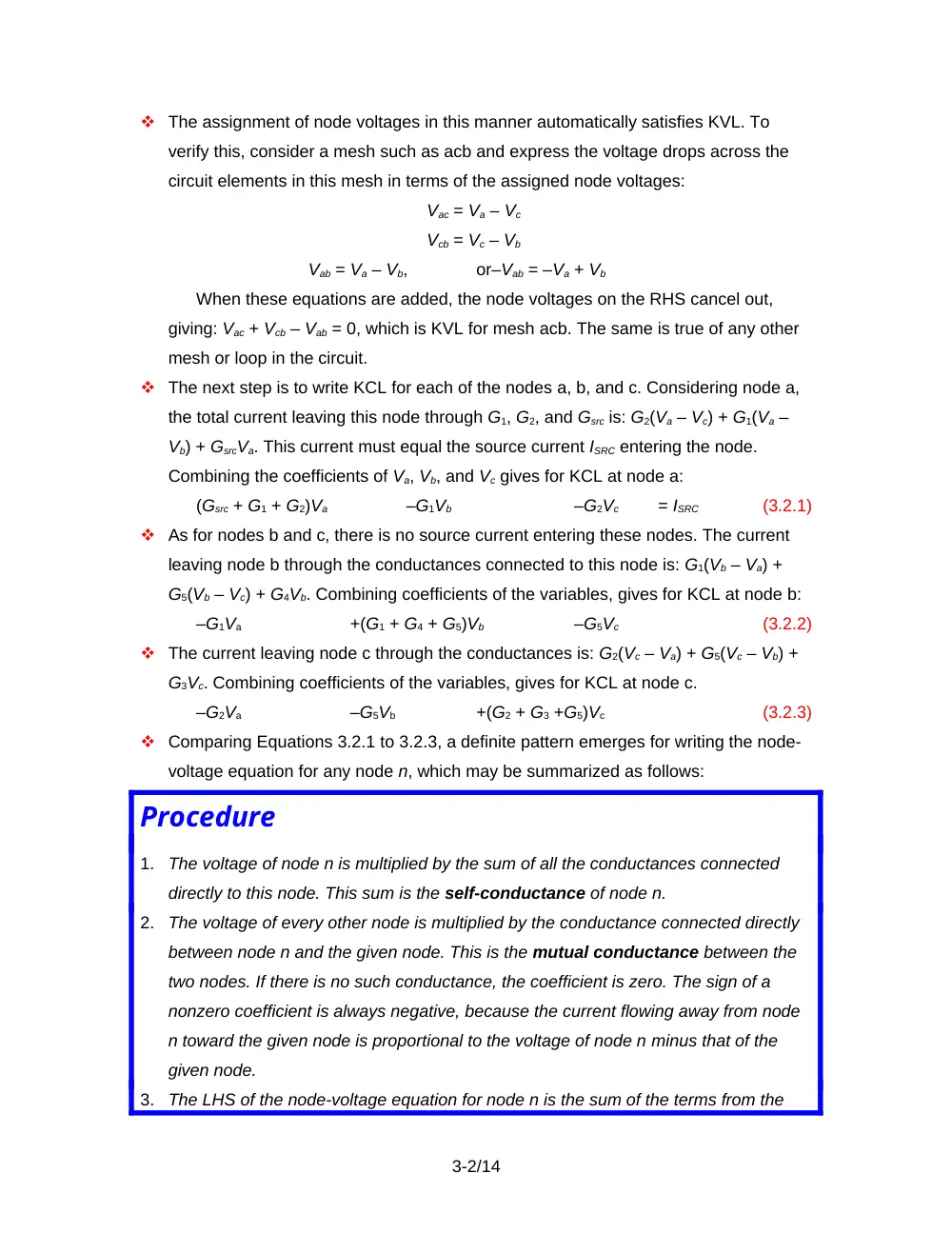
The assignment of node voltages in this manner automatically satisfies KVL. To
verify this, consider a mesh such as acb and express the voltage drops across the
circuit elements in this mesh in terms of the assigned node voltages:
Vac = Va – Vc
Vcb = Vc – Vb
Vab = Va – Vb,
or–Vab = –Va + Vb
When these equations are added, the node voltages on the RHS cancel out,
giving: Vac + Vcb – Vab = 0, which is KVL for mesh acb. The same is true of any other
mesh or loop in the circuit.
The next step is to write KCL for each of the nodes a, b, and c. Considering node a,
the total current leaving this node through G1, G2, and Gsrc is: G2(Va – Vc) + G1(Va –
Vb) + GsrcVa. This current must equal the source current ISRC entering the node.
Combining the coefficients of Va, Vb, and Vc gives for KCL at node a:
(Gsrc + G1 + G2)Va
–G1Vb
–G2Vc
= ISRC
(3.2.1)
As for nodes b and c, there is no source current entering these nodes. The current
leaving node b through the conductances connected to this node is: G1(Vb – Va) +
G5(Vb – Vc) + G4Vb. Combining coefficients of the variables, gives for KCL at node b:
–G1Va
+(G1 + G4 + G5)Vb
–G5Vc
(3.2.2)
The current leaving node c through the conductances is: G2(Vc – Va) + G5(Vc – Vb) +
G3Vc. Combining coefficients of the variables, gives for KCL at node c.
–G2Va
–G5Vb
+(G2 + G3 +G5)Vc
(3.2.3)
Comparing Equations 3.2.1 to 3.2.3, a definite pattern emerges for writing the node-
voltage equation for any node n, which may be summarized as follows:
Procedure
1.
The voltage of node n is multiplied by the sum of all the conductances connected
directly to this node. This sum is the self-conductance of node n.
2.
The voltage of every other node is multiplied by the conductance connected directly
between node n and the given node. This is the mutual conductance between the
two nodes. If there is no such conductance, the coefficient is zero. The sign of a
nonzero coefficient is always negative, because the current flowing away from node
n toward the given node is proportional to the voltage of node n minus that of the
given node.
3.
The LHS of the node-voltage equation for node n is the sum of the terms from the
3-2/14
preceding steps, ordered as the unknown node voltages. This sum is the total
current leaving node n through the conductances connected to this node.
4.
The RHS of the equation is equal to any source current entering node n.
Ideal resistors are bilateral, that is, the resistance is the same for both directions of
current. This means that the mutual conductance terms in the equations of any two
given nodes are the same. For example, the current flowing from node b toward
node c is G5(Vb – Vc) in Figure 3.2.1, whereas the current flowing from node c toward
node b is G5(Vc – Vb). The coefficient of Vc in the node-voltage equation for node b,
which is –G5 in Equation 3.7.2, is the same as the coefficient of Vb in the node-
voltage equation for node c (Equation 3.7.3). When ordered in a matrix, or array, the
conductance coefficients are symmetrical with respect to the diagonal, in the
absence of dependent sources. This is a useful check on the node-voltage
equations.
Example 3.2.1
Node-Voltage Analysis
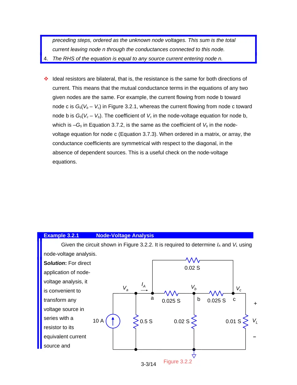
Given the circuit shown in Figure 3.2.2. It is required to determine IA and VL using
node-voltage analysis.
Solution: For direct
application of node-
voltage analysis, it
is convenient to
transform any
voltage source in
series with a
resistor to its
equivalent current
source and
3-3/14
0.01 S
10 A
0.025 S
0.02 S
c
Vc
b
Vb
a
IA
0.5 S
0.025 S
0.02 S
Va
Figure 3.2.2
VL
+
–
represent resistors by their conductances. The lower node is chosen as the reference,
since VL is with respect to this node. Following the procedure outlined above, the node-
voltage equations for nodes a, b, and c, may be written directly:
Va
Vb
Vc
Va
Vb
Vc
Va
Vb
Vc
The conductance coefficients are symmetrical with respect to the diagonal.
Simultaneous equations may be conveniently solved using MATLAB (Appendix SD.1).
The solution is: Va = 19.3 V; Vb = 11.2 V; and Vc = 12.1 V.
IA may be determined as the sum of the currents that flow into the 0.02 S and
0.025 S resistors connected to node a. That is, IA = = 0.346 A. Alternatively, IA = 10 –
0.5Va = 0.346 A. It is seen that VL = Vc = 12.1 V.
3.3
Special Considerations in Node-Voltage Analysis
Dependent Sources
Dependent current sources in node-voltage analysis are treated exactly like
independent sources.
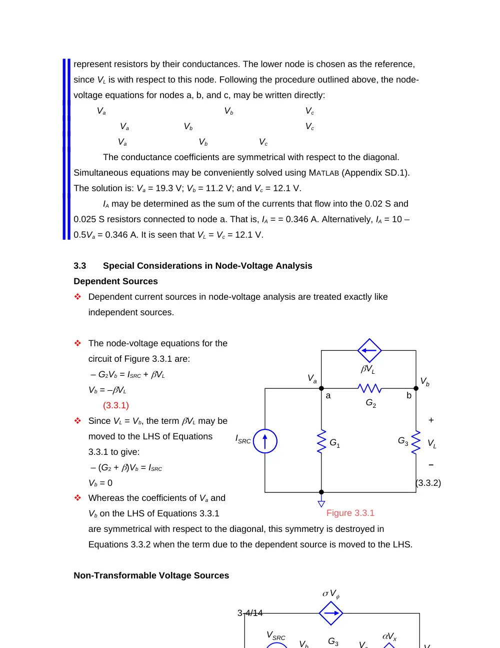
The node-voltage equations for the
circuit of Figure 3.3.1 are:
– G2Vb = ISRC + VL
Vb = –VL
(3.3.1)
Since VL = Vb, the term VL may be
moved to the LHS of Equations
3.3.1 to give:
– (G2 + )Vb = ISRC
Vb = 0
(3.3.2)
Whereas the coefficients of Va and
Vb on the LHS of Equations 3.3.1
are symmetrical with respect to the diagonal, this symmetry is destroyed in
Equations 3.3.2 when the term due to the dependent source is moved to the LHS.
Non-Transformable Voltage Sources
3-4/14
G2
G3
VL
ISRC
G1
a
b
Va
Vb
VL
+
Figure 3.3.1
–
VSRC
V
Vb
Vx
G3
Vc
V
In the circuit of Figure 3.3.2, neither voltage source has a resistance directly in series
with it, so it cannot be transformed to an equivalent current source.
However, if we choose node a as reference, Vb = VSRC, leaving three unknown node
voltages: Vc, Vd, and Ve.
The node equation for node e is:
(3.3.3)
Since the current through the dependent voltage source Vx is not known. An
unknown current I is introduced, which is arbitrarily assigned a direction from node c
to node d. The equation for node c is:
= – I
(3.3.4)
The equation for node d is:
= I + V
(3.3.5)
I is eliminated by adding Equations 3.3.4 and 3.3.5 together:
= V
(3.3.6)
The third equation is the voltage relation for the dependent voltage source:
Vx
(3.3.7)
Substituting Vb = VSRC and , and rearranging the variables, gives three equations that
may be solved for , , and :
VSRC
(3.3.8)
VSRC
(3.3.9)
VSRC
(3.3.10)
Change of Reference Node
If node e is grounded and voltages are required with respect to node e, then all we
have to do is subtract the value of Ve from all the node voltages determined with
node a as reference. If for the circuit of Figure 3.3.2, Va = 0, Vb = 20 V, Vc = 12.5 V,
Vd = 18.5 V, and Ve = 7.97 V, then if node e is grounded, Va = -7.97 V, Vb = 12.0 V,
Vc = 4.51 V, Vd =10.5 V, and Ve = 0.
The justification is simply that the branch voltages, which are the basic quantities
uniquely associated with the branch currents, depend on the difference between the
node voltages at the ends of a given branch and are not changed by adding the
same constant voltage to all the node voltages.
3-5/14
3.4
Mesh-Current Analysis
Concept In mesh-current analysis, the unknown mesh currents are assigned in
such a manner that KCL is automatically satisfied. Equations based on KVL
are then written for each mesh directly in terms of Ohm’s law.
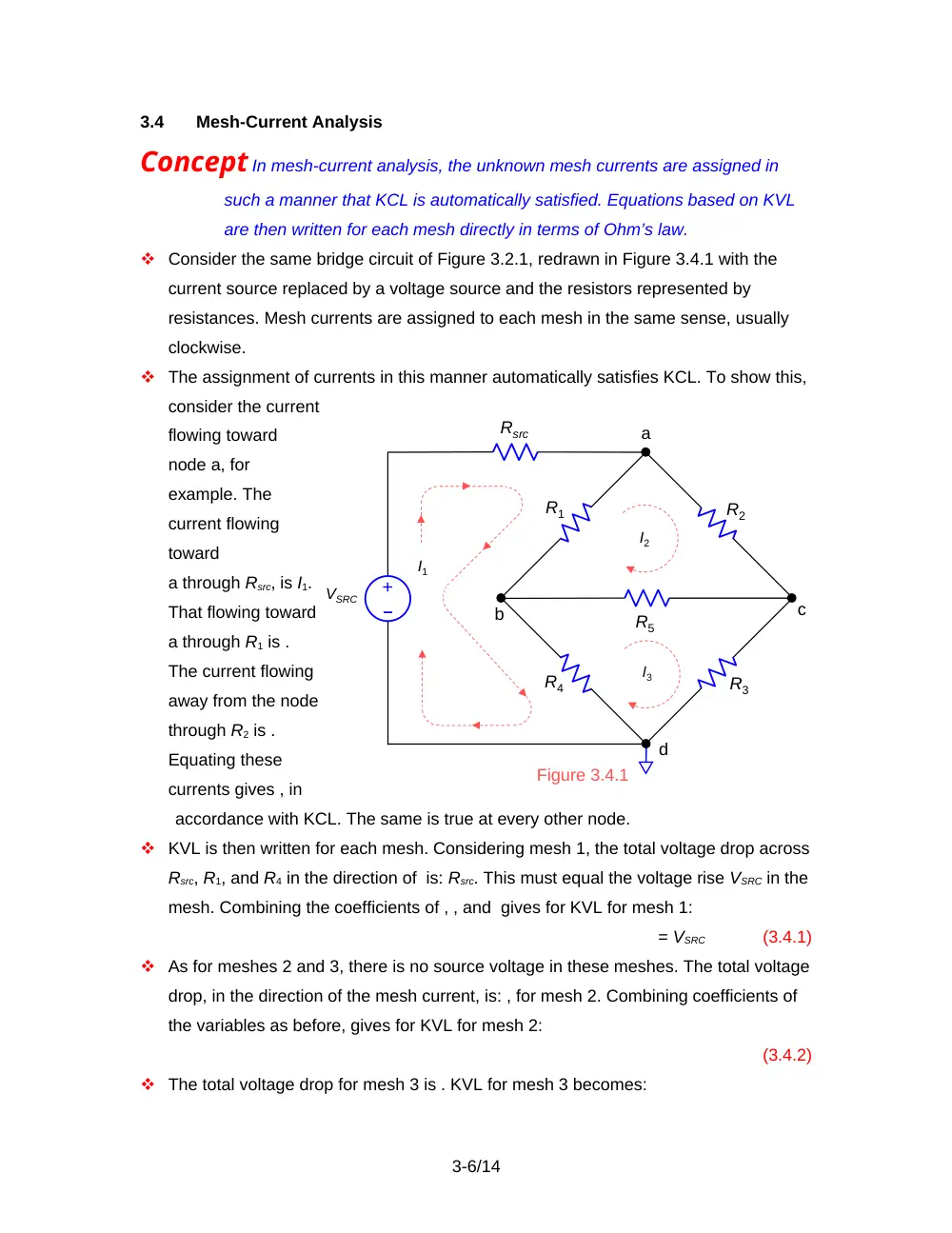
Consider the same bridge circuit of Figure 3.2.1, redrawn in Figure 3.4.1 with the
current source replaced by a voltage source and the resistors represented by
resistances. Mesh currents are assigned to each mesh in the same sense, usually
clockwise.
The assignment of currents in this manner automatically satisfies KCL. To show this,
consider the current
flowing toward
node a, for
example. The
current flowing
toward
a through Rsrc, is I1.
That flowing toward
a through R1 is .
The current flowing
away from the node
through R2 is .
Equating these
currents gives , in
accordance with KCL. The same is true at every other node.
KVL is then written for each mesh. Considering mesh 1, the total voltage drop across
Rsrc, R1, and R4 in the direction of is: Rsrc. This must equal the voltage rise VSRC in the
mesh. Combining the coefficients of , , and gives for KVL for mesh 1:
= VSRC
(3.4.1)
As for meshes 2 and 3, there is no source voltage in these meshes. The total voltage
drop, in the direction of the mesh current, is: , for mesh 2. Combining coefficients of
the variables as before, gives for KVL for mesh 2:
(3.4.2)
The total voltage drop for mesh 3 is . KVL for mesh 3 becomes:
3-6/14
R5
R1
R2
R3
R4
Figure 3.4.1
a
b
c
d
VSRC
–
+
Rsrc
I1
I2
I3
ISRC
40
50
VL
+
50
100
40
+
20 V
I3
I1
I2
2
(3.4.3)
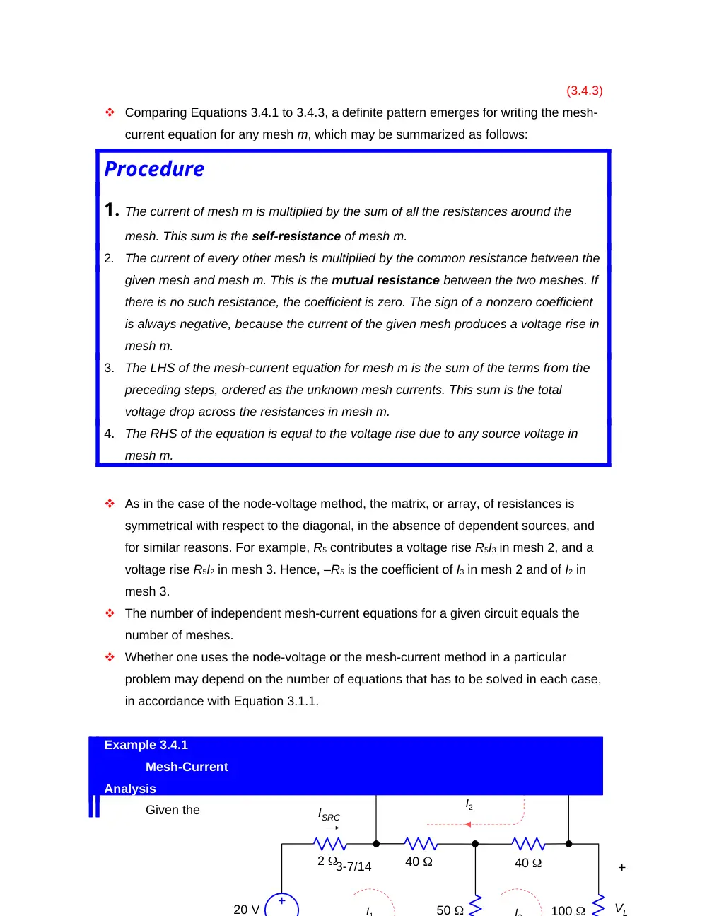
Comparing Equations 3.4.1 to 3.4.3, a definite pattern emerges for writing the mesh-
current equation for any mesh m, which may be summarized as follows:
Procedure
1. The current of mesh m is multiplied by the sum of all the resistances around the
mesh. This sum is the self-resistance of mesh m.
2.
The current of every other mesh is multiplied by the common resistance between the
given mesh and mesh m. This is the mutual resistance between the two meshes. If
there is no such resistance, the coefficient is zero. The sign of a nonzero coefficient
is always negative, because the current of the given mesh produces a voltage rise in
mesh m.
3.
The LHS of the mesh-current equation for mesh m is the sum of the terms from the
preceding steps, ordered as the unknown mesh currents. This sum is the total
voltage drop across the resistances in mesh m.
4.
The RHS of the equation is equal to the voltage rise due to any source voltage in
mesh m.
As in the case of the node-voltage method, the matrix, or array, of resistances is
symmetrical with respect to the diagonal, in the absence of dependent sources, and
for similar reasons. For example, R5 contributes a voltage rise R5I3 in mesh 2, and a
voltage rise R5I2 in mesh 3. Hence, –R5 is the coefficient of I3 in mesh 2 and of I2 in
mesh 3.
The number of independent mesh-current equations for a given circuit equals the
number of meshes.
Whether one uses the node-voltage or the mesh-current method in a particular
problem may depend on the number of equations that has to be solved in each case,
in accordance with Equation 3.1.1.
Example 3.4.1
Mesh-Current
Analysis
Given the
3-7/14
same circuit of Figure 3.2.2. It is required to determine ISRC and VL using mesh-current
analysis.
Solution: The circuit is redrawn
in Figure 3.4.2 showing the mesh currents. The 10 A source in combination with the 0.5
S is transformed to a voltage source of 20 V in series with 2 . Following
the procedure outlined above, the mesh-current equations for meshes 1, 2, and 3 are:
The resistance coefficients are symmetrical with respect to the diagonal. Solving
these equations gives: A; A; A. Hence, I3V, and I1 = IA, as in Example 3.2.1.
3.5
Special Considerations in Mesh-Current Analysis
Dependent Sources.
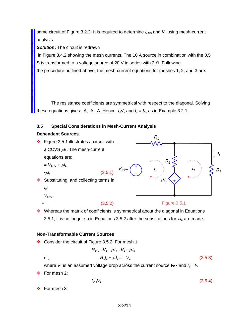
Figure 3.5.1 illustrates a circuit with
a CCVS IL. The mesh-current
equations are:
= VSRC + IL
IL
(3.5.1)
Substituting and collecting terms in
I2:
VSRC
+
(3.5.2)
Whereas the matrix of coefficients is symmetrical about the diagonal in Equations
3.5.1, it is no longer so in Equations 3.5.2 after the substitutions for IL are made.
Non-Transformable Current Sources
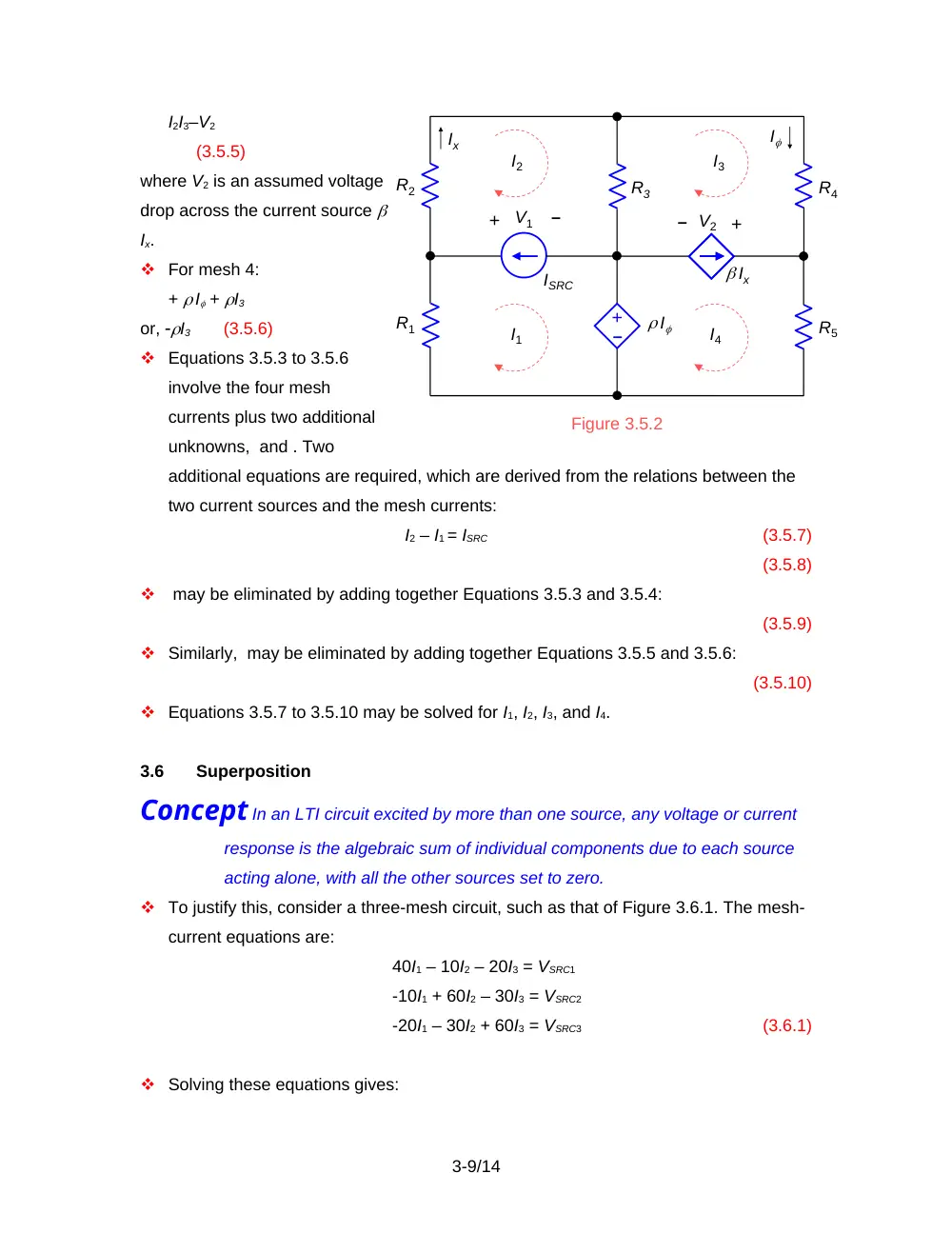
Consider the circuit of Figure 3.5.2. For mesh 1:
R1I1 –V1 I –V1 I3
or,
R1I1 + I3 = –V1
(3.5.3)
where V1 is an assumed voltage drop across the current source ISRC and I = I3.
For mesh 2:
I2I3V1
(3.5.4)
For mesh 3:
3-8/14
R1
R2
R3
IL
IL
VSRC
–
+
–
+
I1
I2
Figure 3.5.1
I2I3–V2
(3.5.5)
where V2 is an assumed voltage
drop across the current source
Ix.
For mesh 4:
+ I + I3
or, I3 (3.5.6)
Equations 3.5.3 to 3.5.6
involve the four mesh
currents plus two additional
unknowns, and . Two
additional equations are required, which are derived from the relations between the
two current sources and the mesh currents:
I2 – I1 = ISRC
(3.5.7)
(3.5.8)
may be eliminated by adding together Equations 3.5.3 and 3.5.4:
(3.5.9)
Similarly, may be eliminated by adding together Equations 3.5.5 and 3.5.6:
(3.5.10)
Equations 3.5.7 to 3.5.10 may be solved for I1, I2, I3, and I4.
3.6
Superposition
Concept In an LTI circuit excited by more than one source, any voltage or current
response is the algebraic sum of individual components due to each source
acting alone, with all the other sources set to zero.
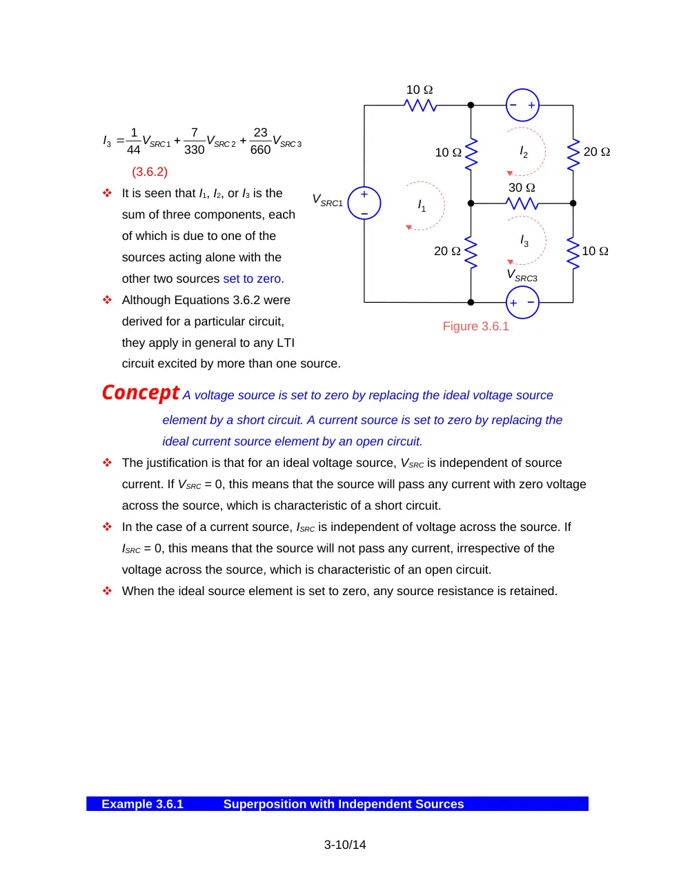
To justify this, consider a three-mesh circuit, such as that of Figure 3.6.1. The mesh-
current equations are:
40I1 – 10I2 – 20I3 = VSRC1
-10I1 + 60I2 – 30I3 = VSRC2
-20I1 – 30I2 + 60I3 = VSRC3
(3.6.1)
Solving these equations gives:
3-9/14
Figure 3.5.2
+
R5
R4
+
R3
R2
R1
–
–
+
–
ISRC
I2
I
I
Ix
I1
I3
I4
Ix
V1
V2
10
VSRC1
–
+
I1
I2
Figure 3.6.1
–
+
–
+
I3
10
10
20
30
20
VSRC3
(3.6.2)
It is seen that I1, I2, or I3 is the
sum of three components, each
of which is due to one of the
sources acting alone with the
other two sources set to zero.
Although Equations 3.6.2 were
derived for a particular circuit,
they apply in general to any LTI
circuit excited by more than one source.
Concept A voltage source is set to zero by replacing the ideal voltage source
element by a short circuit. A current source is set to zero by replacing the
ideal current source element by an open circuit.
The justification is that for an ideal voltage source, VSRC is independent of source
current. If VSRC = 0, this means that the source will pass any current with zero voltage
across the source, which is characteristic of a short circuit.
In the case of a current source, ISRC is independent of voltage across the source. If
ISRC = 0, this means that the source will not pass any current, irrespective of the
voltage across the source, which is characteristic of an open circuit.
When the ideal source element is set to zero, any source resistance is retained.
Example 3.6.1
Superposition with Independent Sources
3-10/14
3
2
1
3
660
23
330
7
44
1
SRC
SRC
SRC
V
V
V
I
It is required to determine VO in the circuit of Figure 3.6.2 using superposition.
Solution: If the
current source is
replaced by an
open circuit, the
resistance between
terminals ab is 30||
60 = 20 . Hence,
V, and VO1 = 12 V, where VO1 is the component of VO due to the voltage source acting
alone.
If the voltage source is replaced by a short circuit, the resistance between
terminals ab is 10||30 = 7.5 . The resistance in parallel with the 40 is 27.5 , and the
resistance across the current source is (27.5)||40 = . Hence, VO2 = 44 V, where VO2 is
the component of VO due to the current source acting alone.
By superposition, VO = 12 + 44 = 56 V.
Dependent Sources
In the presence of dependent sources, superposition can be applied in one of two
ways, depending on which method is easier to apply:
If we consider that the VSRC’s on the RHS of Equations 3.6.1 are due to
independent sources only, then the effect of dependent sources is to modify the
resistance coefficients on the LHS. The implication is that when applying
superposition, dependent sources should remain unaltered.
The dependent source may be replaced by an independent source of assigned,
symbolic value. Superposition is applied and a relation derived for the desired
circuit variable in terms of the assigned value. This relation can then be used with
the dependence relation of the source to solve the problem. In some problems,
this is the quicker solution.
Example 3.6.2
Superposition with Dependent Sources
Given the circuit of Figure
3.6.3. It is required to find VO
using superposition.
3-11/14
10
27 V
40
20
+
–
VO
+
–
2.7 A
30
Figure 3.6.2
a
b
+
20
0.5IO A
+
–
+
20 V
Solution: (a) Leaving the dependent source unaltered. In this case, each of the two
voltage sources is replaced by a short circuit, one at a time, and the two components of
VO determined.
If the 20 V source is replaced by a short circuit, the circuit becomes as shown in
Figure 3.6.4a. Let VO1 be the
component of VO and IO1 be the
current in the leftmost 10
resistor, where VO1 = 10IO1. The
current in the rightmost 10
resistor is also IO1, because the
same voltage VO1 is across this
resistor. The current flowing
away from node b through the
two 10 resistors is 2IO1. Since
0.5IO1 flows toward node b from
the dependent source, it follows from KCL
that a current 1.5IO1 flows toward node b
through the 20 resistor. Applying KVL to
the mesh abca: , or VO1 = 10 V.
When the 40 V source is replaced
by a short circuit, the circuit becomes as
shown in Figure 3.6.4b. Let
VO2 be the component of VO and IO2 be the
current in the leftmost 10 resistor, where
VO2 = 10IO2. Since VO2 is also across the 20
resistor, the current through this resistor
is 0.5IO2. From KCL at node b, the current through the 20 V source is 1.5IO2. as shown.
From KCL at node d, the current in the rightmost 10 resistor is IO2 directed upward.
Hence, the voltage across this resistor is also VO2 in the polarity shown. Applying KVL to
the mesh bcd gives 20 = 2VO2, or VO2 = 10 V. From superposition, VO = VO1 + VO2 = 20 V.
(b) Dependent source treated as an independent source. The dependent source is
assigned a value, say Ix as an independent source (Figure 3.6.5) and superposition is
applied with each of the three
sources acting alone. When the
3-12/14
–
+
40 V
20
IO1
0.5IO1 A
+
–
VO1
10
10
(a)
IO1
0.5IO1
1.5IO1
a
b
c
Figure 3.6.4
20
IO2
0.5IO2 A
+
–
VO2
–
+
10
10
20 V
(b)
0.5IO2
b
c
1.5IO2
IO2
0.5IO2
d
+
–
VO2
+
20
Ix
+
V
–
+
20 V
40 V source is applied alone, with the 20 V replaced by a short circuit and Ix by an open
circuit, 8 V. When the 20 V source is applied alone, with the 40 V replaced by a short
circuit and Ix by an open circuit, V. When Ix is applied alone, with the two voltage sources
replaced by short circuits, VO3 = (10||10||20)Ix. To calculate the parallel resistance, the
two 10 resistors in parallel give 5 . This resistance in parallel with 20 is 4, so that
VO3 = 4Ix. It follows that VO = VO1 + VO2 + VO3 = 16 + 4Ix. From the original circuit (Figure
3.6.3), , so that . Substituting, gives V, as before.
Power with Superposition
Concept In a circuit excited by more than one source, the total power dissipated in
a given resistor is NOT the sum of the powers due to each source acting
alone, with all the other sources set to zero.
The reason is that the power dissipated in a given resistor is proportional to the
square of the current through the resistor, or the square of the voltage across it, and
the sum of the squares of a set of quantities is not equal to the square of the sum of
these quantities. Thus, in Example 3.6.2, part(a), VO1 = VO2 = 10 V. The sum of the
powers due to these components is W. The true power dissipated is W.
Scaling of Input
Concept In a circuit excited by a single independent source, multiplying the
excitation by a constant K, multiplies all the voltage and current responses by
the same constant.
If only a single excitation, say , is applied to the circuit of Figure 3.6.1, Equations
3.6.2 become, with VSRC2 = VSRC3 = 0:
,
(3.6.3)
If VSRC1 is multiplied by K, then I1, I2, and I3 are also multiplied by K. This fact may be
usefully exploited in some problems by working backwards. That is, rather than
determine the output for a given input, a convenient output is assumed and the input
that produces this output is determined. The desired output is then obtained by
simple scaling according to the given input
Example 3.6.3
Scaling Applied to a Ladder Circuit
It is required to
3-13/14
20 V
+
–
1
1
1
1
1
1
IO
determine IO in the ladder circuit of Figure 3.6.7.
Solution: The quickest way to solve this problem is to assume a convenient value for IO
and work backwards towards the source. If IO = 1 A (Figure 3.6.8), Vcc’ = 3 V and the
current in the cc’ branch is 3 A. The current in the bc and c’b’ branches is 4 A, and Vbb’ =
11 V. That makes the source
current 15 A, and the
source voltage 41 V. But the
given source is 20 V; so the
actual value of IO is A.
Excitation by Dependent
Sources
It follows from Equations 3.6.2 that if the circuit
has dependent sources only, then all the VSRC’s
are zero and hence all the responses are zero.
In Figure 3.6.9, for example, , and . Substituting, ,
which is impossible unless V = 0. This means
that the source current is zero and all responses
in the circuit are zero.
In some cases, dependent sources can make the
circuit unstable and the response theoretically increases with time without limit.
Hence, a more accurate statement is:
Concept In a stable LTI circuit containing dependent sources, and no independent
sources, all circuit responses are zero.
3-14/14
Figure 3.6.9
3
–
+
V
V
3
3
3
a
b
41 V
15 A
11A
1 A
4 A
3 A
15 A
4 A
c
c
b
b
+
–
Figure 3.6.8