
EECE 210 Chapter 4, Fall 2012
American University of Beirut · Electric Circuits · 12 pages

Showing the first 10 of 12 pages. Download the PDF to see all of it.
More EECE 210 files
- Chapter Uploading Chapter 08 Sinusoidal Steady · Spring 2015ChapterView
- Homework All Chapters · Fall 2015ChapterView
- Chapter 1 · Fall 2012ChapterView
- Chapter 2 · Fall 2012ChapterView
- Chapter 3 · Fall 2012ChapterView
- Chapter 5 · Fall 2012ChapterView
- Chapter 6 · Fall 2012ChapterView
- Chapter 7 · Fall 2012ChapterView
Show the text of this chapter
Chapter 4
Circuit Simplification
4.1
Thevenin’s Equivalent Circuit
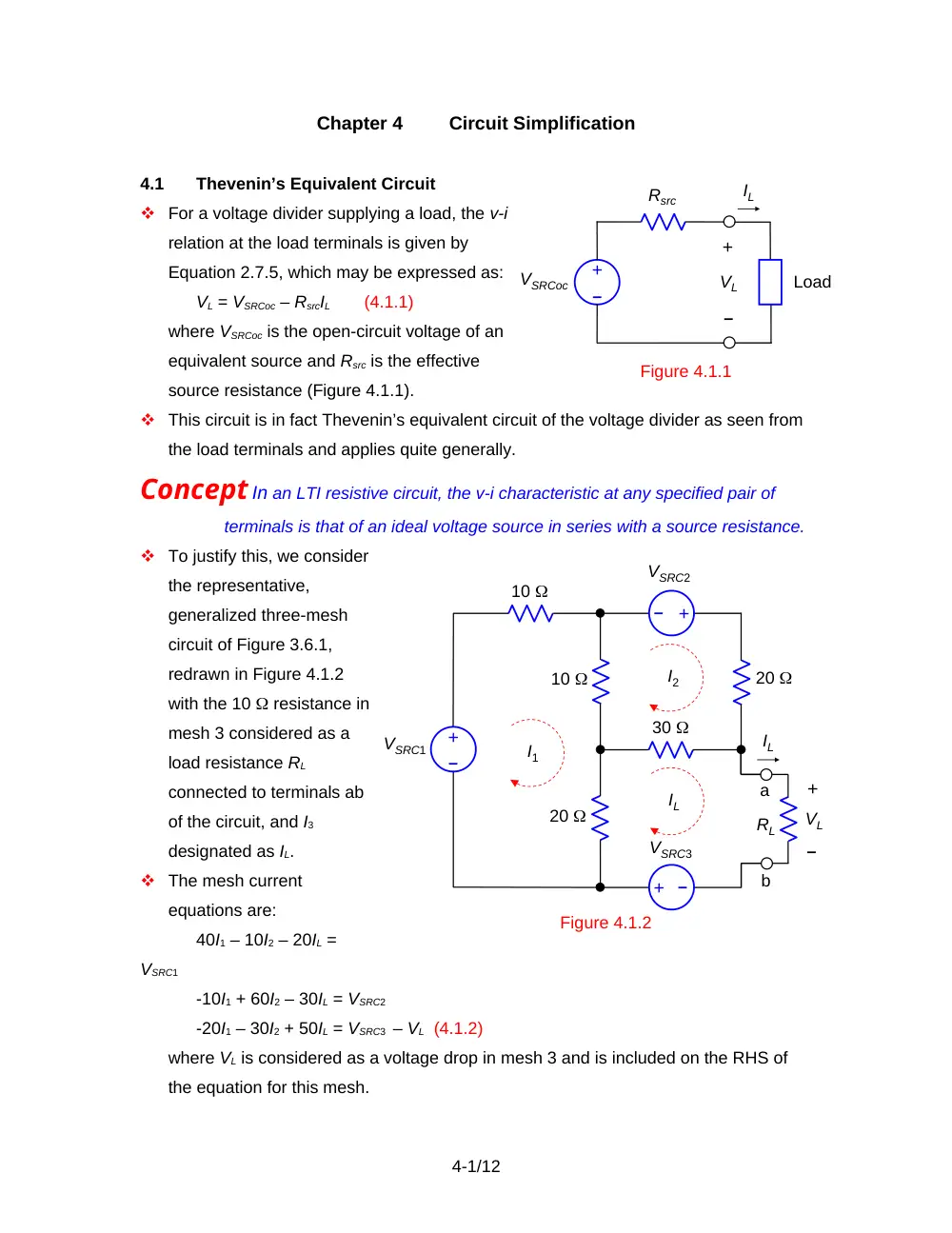
For a voltage divider supplying a load, the v-i
relation at the load terminals is given by
Equation 2.7.5, which may be expressed as:
VL = VSRCoc – RsrcIL
(4.1.1)
where VSRCoc is the open-circuit voltage of an
equivalent source and Rsrc is the effective
source resistance (Figure 4.1.1).
This circuit is in fact Thevenin’s equivalent circuit of the voltage divider as seen from
the load terminals and applies quite generally.
Concept In an LTI resistive circuit, the v-i characteristic at any specified pair of
terminals is that of an ideal voltage source in series with a source resistance.
To justify this, we consider
the representative,
generalized three-mesh
circuit of Figure 3.6.1,
redrawn in Figure 4.1.2
with the 10 resistance in
mesh 3 considered as a
load resistance RL
connected to terminals ab
of the circuit, and I3
designated as IL.
The mesh current
equations are:
40I1 – 10I2 – 20IL =
VSRC1
-10I1 + 60I2 – 30IL = VSRC2
-20I1 – 30I2 + 50IL = VSRC3 – VL (4.1.2)
where VL is considered as a voltage drop in mesh 3 and is included on the RHS of
the equation for this mesh.
4-1/12
Figure 4.1.1
Rsrc
–
+
+
–
VL
Load
VSRCoc
IL
10
VSRC1
–
+
I1
I2
Figure 4.1.2
–
+
–
+
IL
10
RL
20
30
20
VSRC2
VSRC3
–
+
VL
IL
a
b
Solving for IL and rearranging:
(4.1.3)
Equation 4.1.3 is of the form of Eq 4.1.1, where VSRCoc equals the bracketed terms,
and Rsrc = 430/23. Since the circuit of Figure 4.1.2 is quite arbitrary, it is concluded
that the v-i relation for any given circuit at specified terminals ab is the same, in
general, as that of an ideal voltage source VSRCoc in series with a resistance Rsrc.
The VSRCoc-Rsrc circuit is the TEC of the given circuit at terminals ab and is the
simplest possible equivalent circuit, since it consists of just an ideal source and a
resistor. It is customary to refer to VSRCoc as the Thevenin voltage VTh, and to Rsrc as
the Thevenin resistance RTh.
VTh is determined as the open-circuit voltage at specified pair of terminals. If
terminals ab in Figure 4.1.2 are open circuited, IL = 0 and the mesh current equations
for the circuit become:
40I1 – 10I2 = VSRC1
-10I1 + 60I2 = VSRC2
(4.1.4)
Solving for I1 and I2, and . From KVL, VL = 30I2 + 20I1 + VSRC3. This gives:
(4.1.5)
which is the open-circuit voltage determined above.
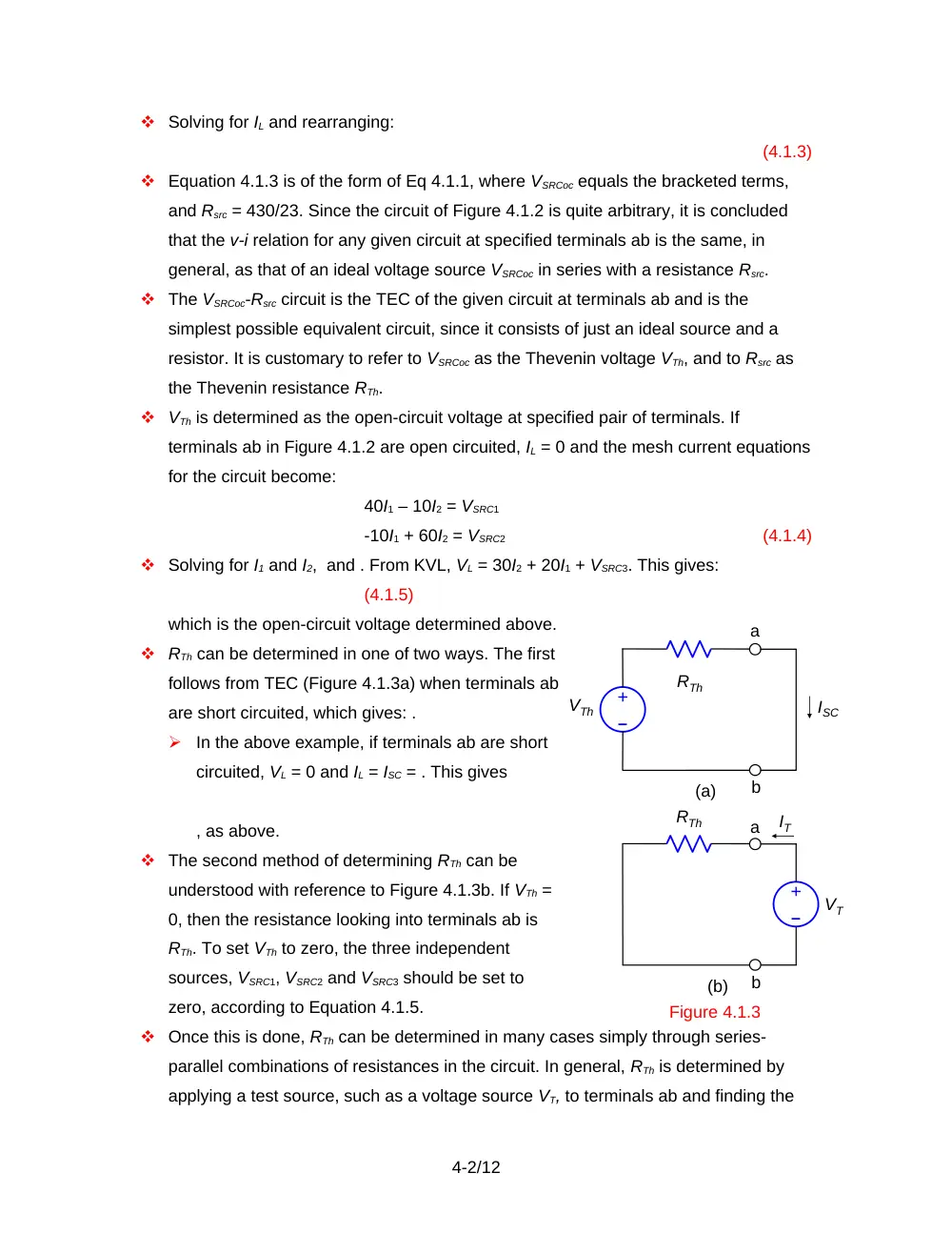
RTh can be determined in one of two ways. The first
follows from TEC (Figure 4.1.3a) when terminals ab
are short circuited, which gives: .
In the above example, if terminals ab are short
circuited, VL = 0 and IL = ISC = . This gives
, as above.
The second method of determining RTh can be
understood with reference to Figure 4.1.3b. If VTh =
0, then the resistance looking into terminals ab is
RTh. To set VTh to zero, the three independent
sources, VSRC1, VSRC2 and VSRC3 should be set to
zero, according to Equation 4.1.5.
Once this is done, RTh can be determined in many cases simply through series-
parallel combinations of resistances in the circuit. In general, RTh is determined by
applying a test source, such as a voltage source VT, to terminals ab and finding the
4-2/12
Figure 4.1.3
RTh
–
+
VTh
ISC
a
b
RTh
–
+
IT
a
b
VT
(a)
(b)
Figure 4.1.4
RN
+
–
VL
Load
IN
IL
resulting current IT as a function of VT.
In summary:
Procedure
The derivation of TEC of a given circuit between a specified pair of
terminals involves in general the following steps:
1.
Determining the open-circuit voltage VTh at the specified terminals.
2.
Determining the short-circuit current ISC at the specified terminals.
3.
Setting independent sources to zero and determining the resistance RTh
looking into the specified terminals. RTh is then determined either directly, or
by applying a test voltage and finding the test current.
Since VTh = RThISC, only two of the three quantities in this relation need be
determined through the above steps. However, it is useful for checking purposes to
determine all three independently.
Dependent sources affect the resistance values in the circuit. They should not be set
to zero in determining RTh, as this will change the circuit.
Norton’s Equivalent Circuit.
When the source VTh, in conjunction with RTh,
is transformed to an equivalent current
source, Norton’s equivalent circuit (NEC) is
obtained (Figure 4.1.4).
It follows from source transformation that:
,
(4.1.6)
Example 4.1.1
TEC and NEC
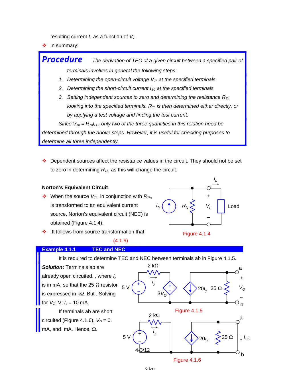
It is required to determine TEC and NEC between terminals ab in Figure 4.1.5.
Solution: Terminals ab are
already open circuited. , where Iy
is in mA, so that the 25 resistor
is expressed in k. But . Solving
for VO: V; Iy = 10 mA.
If terminals ab are short
circuited (Figure 4.1.6), VO = 0.
mA, and mA. Hence, .
4-3/12
–
+
25
5 V
2 k
Iy
–
+
3VO
20Iy
+
–
VO
a
b
Figure 4.1.5
–
+
5 V
2 k
Iy
20Iy
a
b
ISC
Figure 4.1.6
25
2 k
If VT is applied, with the 5 V source replaced by a short circuit (Figure 4.1.7), Iy
= . From KCL at node a, IT = . Hence, k 100 .
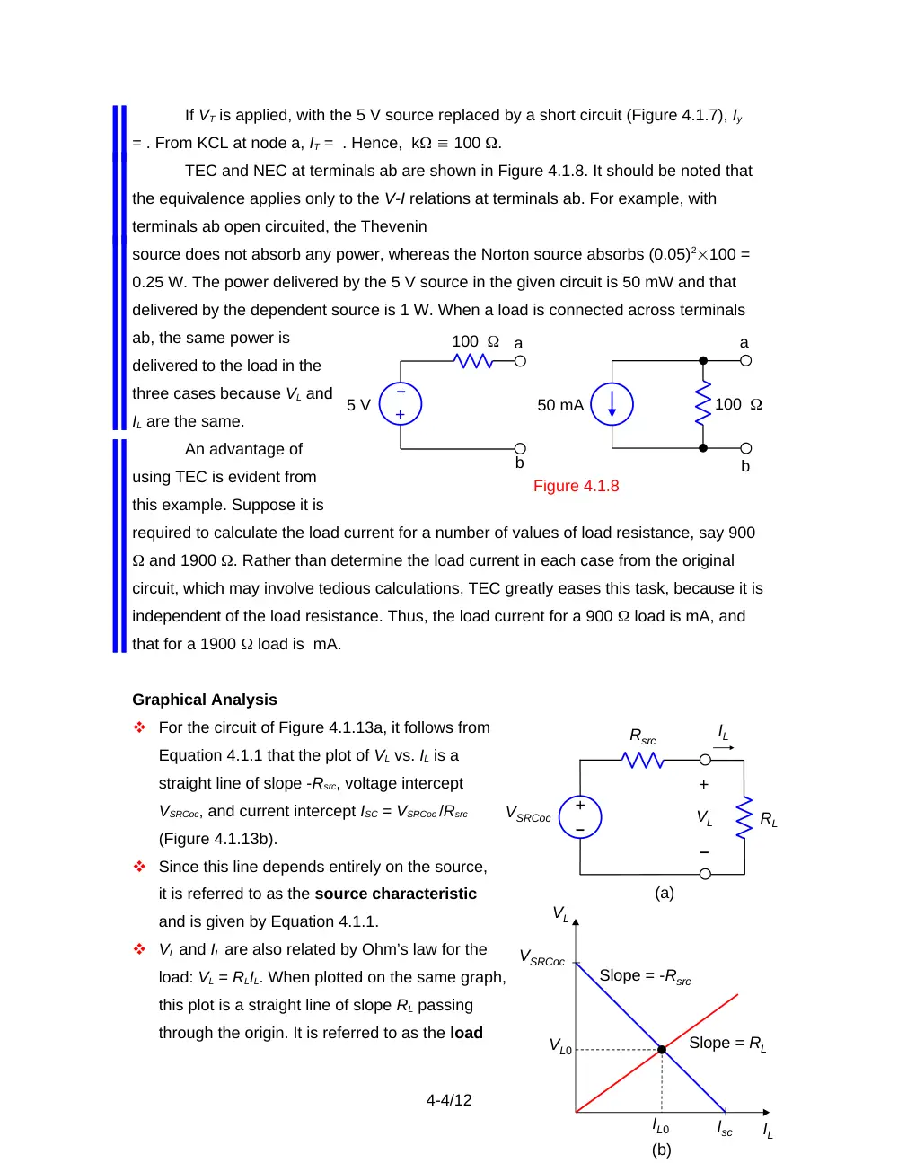
TEC and NEC at terminals ab are shown in Figure 4.1.8. It should be noted that
the equivalence applies only to the V-I relations at terminals ab. For example, with
terminals ab open circuited, the Thevenin
source does not absorb any power, whereas the Norton source absorbs (0.05)2100 =
0.25 W. The power delivered by the 5 V source in the given circuit is 50 mW and that
delivered by the dependent source is 1 W. When a load is connected across terminals
ab, the same power is
delivered to the load in the
three cases because VL and
IL are the same.
An advantage of
using TEC is evident from
this example. Suppose it is
required to calculate the load current for a number of values of load resistance, say 900
and 1900 . Rather than determine the load current in each case from the original
circuit, which may involve tedious calculations, TEC greatly eases this task, because it is
independent of the load resistance. Thus, the load current for a 900 load is mA, and
that for a 1900 load is mA.
Graphical Analysis
For the circuit of Figure 4.1.13a, it follows from
Equation 4.1.1 that the plot of VL vs. IL is a
straight line of slope -Rsrc, voltage intercept
VSRCoc, and current intercept ISC = VSRCoc /Rsrc
(Figure 4.1.13b).
Since this line depends entirely on the source,
it is referred to as the source characteristic
and is given by Equation 4.1.1.
VL and IL are also related by Ohm’s law for the
load: VL = RLIL. When plotted on the same graph,
this plot is a straight line of slope RL passing
through the origin. It is referred to as the load
4-4/12
5 V
100
a
b
a
b
50 mA
–
+
100
Figure 4.1.8
Rsrc
–
+
+
–
VL
VSRCoc
IL
RL
(a)
VL
IL
Isc
Slope = -Rsrc
VSRCoc
(b)
VL0
IL0
Slope = RL
line.
The intersection point of the load line and the source characteristic gives VL0 and IL0
for particular values of VSRCoc, Rsrc, and RL. This is because both the source
characteristic and the load line equation are satisfied at the intersection point.
4.2
Substitution Theorem
Statement
An unknown resistor having a voltage V across it, or a current I
through it, may be replaced by an ideal, independent voltage source V, or
an ideal, independent current source I, without disturbing the rest of the
circuit.
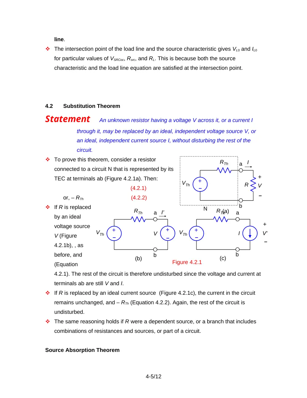
To prove this theorem, consider a resistor
connected to a circuit N that is represented by its
TEC at terminals ab (Figure 4.2.1a). Then:
(4.2.1)
or, – RTh
(4.2.2)
If R is replaced
by an ideal
voltage source
V (Figure
4.2.1b), , as
before, and
(Equation
4.2.1). The rest of the circuit is therefore undisturbed since the voltage and current at
terminals ab are still V and I.
If R is replaced by an ideal current source (Figure 4.2.1c), the current in the circuit
remains unchanged, and – RTh (Equation 4.2.2). Again, the rest of the circuit is
undisturbed.
The same reasoning holds if R were a dependent source, or a branch that includes
combinations of resistances and sources, or part of a circuit.
Source Absorption Theorem
4-5/12
(a)
V
–
+
N
–
+
VTh
RTh
a
b
R
I
Figure 4.2.1
(b)
I'
a
b
V
–
+
(c)
I
a
b
–
+
V'
–
+
VTh
RTh
–
+
VTh
RTh
This is a weaker form of the substitution theorem, which may be stated as follows:
Statement
A resistor of known value having a voltage V across it AND a
current I through it, may be replaced by a CCVS having V = RI, or a VCCS
having I = V/ R. Conversely, a CCVS having V = I may be replaced by a
resistance , and a VCCS having I = V may be replaced by a conductance
, where
V is the voltage across the source and I is the current through it.
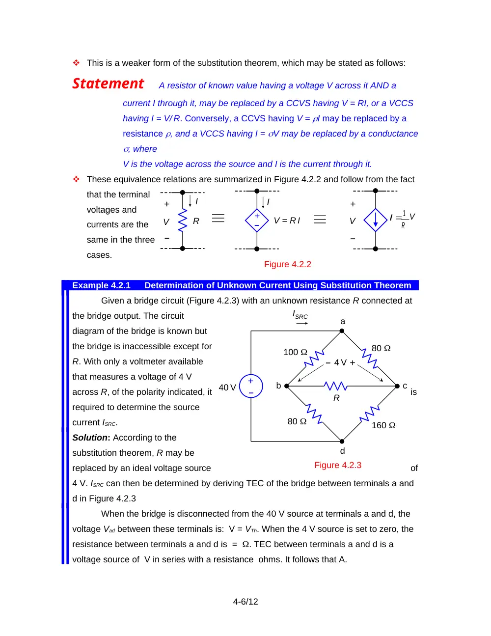
These equivalence relations are summarized in Figure 4.2.2 and follow from the fact
that the terminal
voltages and
currents are the
same in the three
cases.
Example 4.2.1
Determination of Unknown Current Using Substitution Theorem
Given a bridge circuit (Figure 4.2.3) with an unknown resistance R connected at
the bridge output. The circuit
diagram of the bridge is known but
the bridge is inaccessible except for
R. With only a voltmeter available
that measures a voltage of 4 V
across R, of the polarity indicated, it
is
required to determine the source
current ISRC.
Solution: According to the
substitution theorem, R may be
replaced by an ideal voltage source
of
4 V. ISRC can then be determined by deriving TEC of the bridge between terminals a and
d in Figure 4.2.3
When the bridge is disconnected from the 40 V source at terminals a and d, the
voltage Vad between these terminals is: V = VTh. When the 4 V source is set to zero, the
resistance between terminals a and d is = . TEC between terminals a and d is a
voltage source of V in series with a resistance ohms. It follows that A.
4-6/12
Figure 4.2.2
R
+
V
+
V
I
–
–
R
I 1
V
I
+
–
V = R I
–
+
–
+
a
b
80
100
80
160
c
d
R
4 V
40 V
ISRC
Figure 4.2.3
4.3
Source Rearrangement
Concept Sources may be rearranged in a circuit, so as to facilitate analysis of the
circuit, without affecting circuit responses, as long as KCL and KVL remain
satisfied.
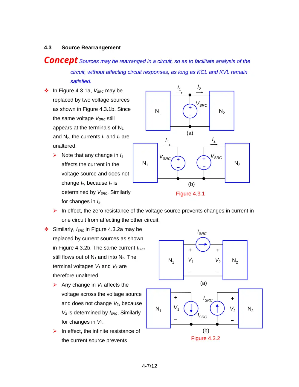
In Figure 4.3.1a, VSRC may be
replaced by two voltage sources
as shown in Figure 4.3.1b. Since
the same voltage VSRC still
appears at the terminals of N1
and N2, the currents I1 and I2 are
unaltered.
Note that any change in I1
affects the current in the
voltage source and does not
change I2, because I2 is
determined by VSRC, Similarly
for changes in I2.
In effect, the zero resistance of the voltage source prevents changes in current in
one circuit from affecting the other circuit.
Similarly, ISRC in Figure 4.3.2a may be
replaced by current sources as shown
in Figure 4.3.2b. The same current ISRC
still flows out of N1 and into N2. The
terminal voltages V1 and V2 are
therefore unaltered.
Any change in V1 affects the
voltage across the voltage source
and does not change V2, because
V2 is determined by ISRC, Similarly
for changes in V2.
In effect, the infinite resistance of
the current source prevents
4-7/12
Figure 4.3.1
N2
N1
VSRC
I1
I2
–
+
(a)
N2
N1
VSRC
I1
I2
–
+
(b)
VSRC
–
+
Figure 4.3.2
N2
N1
ISRC
(a)
+
–
V2
+
–
V1
N2
N1
ISRC
(b)
ISRC
+
–
V1
+
–
V2
changes in the voltage in one circuit from affecting the other circuit.
Example 4.3.1
Source Rearrangement
It is required to determine Ix in Figure 4.3.3
using source rearrangement.
Solution: The voltage source and current source
may each be split into two sources as shown in
Figure 4.3.4. In Figure 4.3.3, a current of 10 A enters
node b from the source and a current of 10 A leaves
node a. The same conditions are preserved in Figure
4.3.4. A source current of 10 A both enters and
leaves node c in Figure 4.3.4, so that the net source
current at this node is zero, as in Figure 4.3.3. Ix will
be determined in two ways:
Method 1: The
first method is
to derive TEC
between nodes
b and a. The
open-circuit
voltages
between nodes
a and c, and
between nodes b and c will be determined by superposition.
When the 6 resistor
is removed, and the A sources set to zero, V, and 4 V. Hence, nodes a and b will be at
the same voltage, and this component of Vba is zero. If the 10 V sources are set to zero,
V, and V. It follows that Vba = VTh = 36 V. With all sources set to zero, RTh = (4||6) + (2||3)
= 3.6 . Hence A.
Method 2: The second method is based on the substitution theorem and source
transformation. The 6 resistor is replaced by a current source Ix, in accordance with
the substitution theorem, which adds Ix to the two 10 A sources. The 10 V source on the
RHS in Figure 4.3.4 is transformed to a 5/3 A current source. The parallel resistance of 6
and 4 is 12/5 , and . Similarly the 10 V source
on the LHS in Figure 4.3.4 is transformed to 10/3 A current source in parallel with 6/5
,and . From the circuit without the 6 resistor replaced by a current source, .
4-8/12
Figure 4.3.3
–
+
10 V
3
6
4
2
6
10 A
Ix
a
b
Iy
Figure 4.3.4
–
+
10 V
3
6
4
2
6
Ix
a
b
10 A
–
+
10 V
10 A
c
Substituting gives A.
4.4
Removal of Redundant Elements
Concept
Redundant elements can be removed from a circuit without affecting the
circuit responses of interest.
Examples of redundant elements are:
A resistor in series with an ideal current source. When this series resistor is
removed, that is, replaced by a short circuit, the source current is unchanged.
The voltage across the source decreases by an amount equal to the voltage drop
across the resistor, but the rest of the circuit is not disturbed.
A resistor in parallel with an ideal voltage source. When this parallel resistor is
removed, that is, replaced by an open circuit, the source voltage is unchanged.
The current through the source decreases by an amount equal to the current
through the resistor, but the rest of the circuit is not disturbed.
Resistors that do not carry any current. These may be replaced by an open
circuit or a short circuit without disturbing the rest of the circuit.
Inductors and capacitors in a circuit under DC operating conditions. The inductor
is replaced by a short circuit and the capacitor by an open circuit, as discussed in
sections 1.8 and 1.9.
Example 4.4.1
Redundant Elements
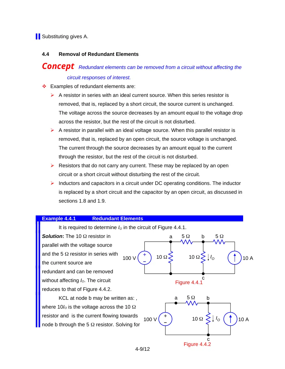
It is required to determine IO in the circuit of Figure 4.4.1.
Solution: The 10 resistor in
parallel with the voltage source
and the 5 resistor in series with
the current source are
redundant and can be removed
without affecting IO. The circuit
reduces to that of Figure 4.4.2.
KCL at node b may be written as: ,
where 10IO is the voltage across the 10
resistor and is the current flowing towards
node b through the 5 resistor. Solving for
4-9/12
5
Figure 4.4.1
100 V
10
10
10 A
IO
–
+
5
a
b
c
Figure 4.4.2
5
100 V
10
10 A
IO
–
+
a
b
c
IO gives A.
The two resistors do not affect IO. In Figure 4.4.2, the current through the voltage
source is zero and the voltage across the current source is 100 V. In Figure 4.4.1, the
current through the voltage source is 10 A, and the voltage across the current source is
150 V.
4.5
Exploitation of Symmetry
Concept In circuits possessing symmetry, the circuit may be simplified by removing
elements that do not carry current, or by connecting together nodes that are
at the same voltage.
Example 4.5.1
Exploitation of Symmetry
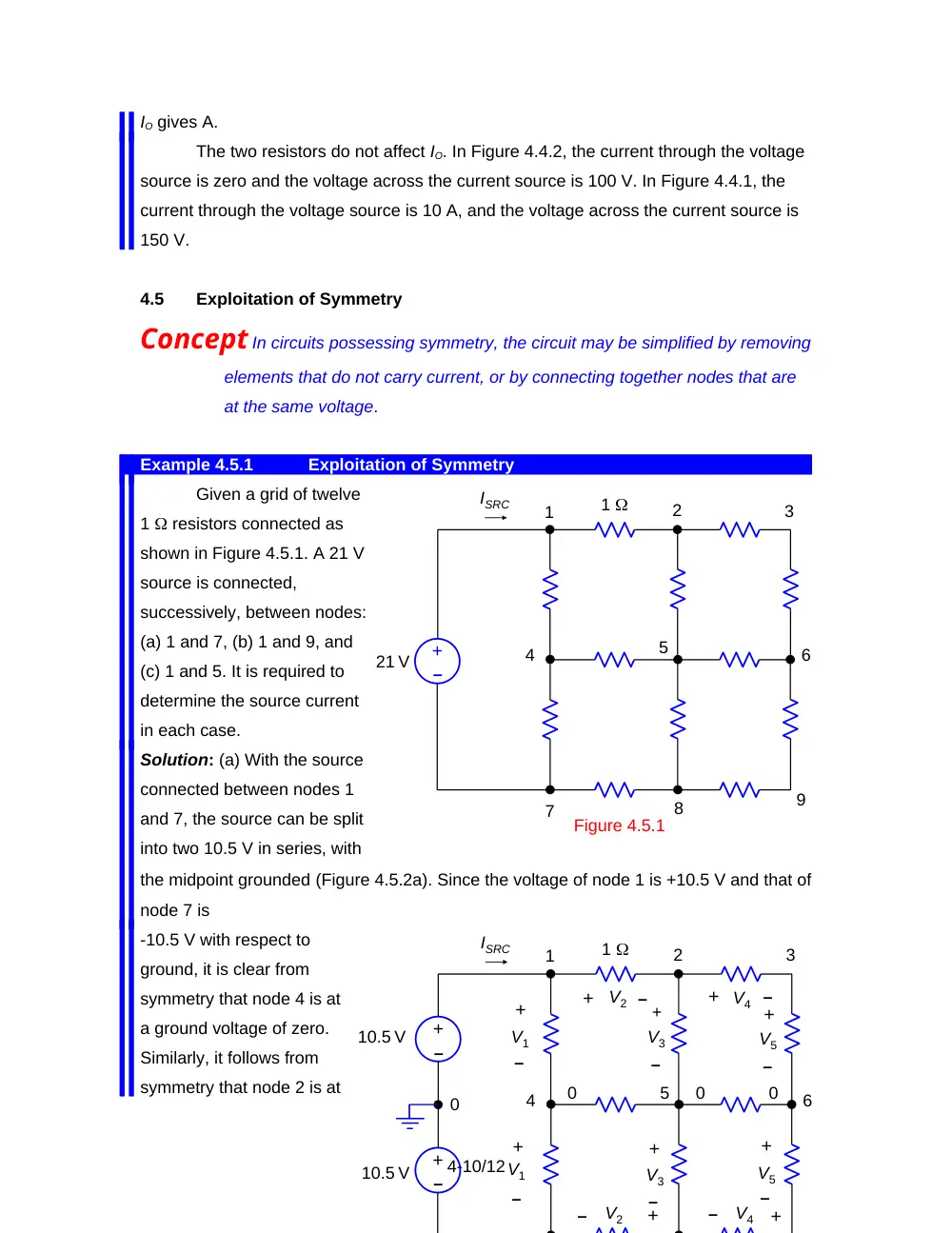
Given a grid of twelve
1 resistors connected as
shown in Figure 4.5.1. A 21 V
source is connected,
successively, between nodes:
(a) 1 and 7, (b) 1 and 9, and
(c) 1 and 5. It is required to
determine the source current
in each case.
Solution: (a) With the source
connected between nodes 1
and 7, the source can be split
into two 10.5 V in series, with
the midpoint grounded (Figure 4.5.2a). Since the voltage of node 1 is +10.5 V and that of
node 7 is
-10.5 V with respect to
ground, it is clear from
symmetry that node 4 is at
a ground voltage of zero.
Similarly, it follows from
symmetry that node 2 is at
4-10/12
+
–
1
21 V
1
2
3
4
5
6
7
8
9
ISRC
Figure 4.5.1
+
–
1
10.5 V
1
2
3
4
5
6
V2
V4
V1
V3
V5
V2
V4
V1
V3
V5
+
–
+
–
+
–
+
–
+
–
+
–
+
–
+
–
+
–
+
–
ISRC
+
–
10.5 V
0
0
0
0
a voltage 10.5 – V2, whereas node 8 is at -10.5 + V2, where V2 is a positive voltage drop.
This means that the voltages of nodes 2 and 8 are equal in magnitude but opposite in
sign. Node 5 is therefore at zero voltage. Since nodes 2 and 6 are connected by a
resistance of 2 , as are nodes 6 and 8, then node 6 is also at a node voltage of zero.
Hence, the resistors between nodes 4 and 5, and between nodes 5 and 6, do not carry
any current. They could just as well be replaced by open circuits or short circuits. If they
are replaced by open circuits, the circuit reduces to that shown in Figure 4.5.2b. The
series-parallel combination of resistances evaluates to 1.25 across the source, so that
ISRC = 16.8 A.
Alternatively, it may be argued that the circuit of Figure 4.5.2a is symmetrical
about a horizontal line passing through nodes 4, 5, 6, and the ground between the split
sources. Voltages above this line are positive, whereas voltages below this line is
negative. Hence, voltages along the line are zero.
(b) If the 21 V source is connected between
nodes 1 and 9 (Figure 4.5.1), the circuit
becomes symmetrical about the diagonal and
could be split into two halves alon the
diagonal. Figure 4.5.3a shows the source
applied to one hal-circuit. The half-circuit can
be reduced to that shown in Figure 4.5.3b,
from which it follows that the current drawn
by the half circuit is 7 A, so that Isrc = 14 A.
4-11/12
+
–
21 V
1
2
3
5
6
9
(a)
+
–
1
21 V
1
9
7 A
1
Figure 4.5.3
(b)
2
6
1
(c) When the 21 V source is connected between
nodes 1 and 5 (Figure 4.5.4a), the currents are
symmetrical about the diagonal through nodes 1,
5, and 9. Thus, the current from node 1 to node 2
equals that from node 1 to node 4, the current
from node 3 to node 6 equals that from node 7 to
node 8, and the current from node 6 to node 9
equals that from node 8 to node 9. The currents
at node 9 are therefore equal and sum to zero.
Hence, each of them must be zero. It follows that
the two resistors connected to node 9 do not
carry current and may be removed. The resulting circuit becomes as shown in Figure
4.5.5b. The resistance on either side of the source is 7/4 . The effective resistance
across the source is 7/8 , so that ISRC = 24 A.
4-12/12
+
–
1
2
3
4
5
6
7
8
9
21 V
0
0
(a)
+
–
1
21 V
1
1
3
3
1
Figure 4.5.4
(b)