
EECE 210 Chapter 6, Fall 2012
American University of Beirut · Electric Circuits · 19 pages


Showing the first 10 of 19 pages. Download the PDF to see all of it.
More EECE 210 files
- Chapter Uploading Chapter 08 Sinusoidal Steady · Spring 2015ChapterView
- Homework All Chapters · Fall 2015ChapterView
- Chapter 1 · Fall 2012ChapterView
- Chapter 2 · Fall 2012ChapterView
- Chapter 3 · Fall 2012ChapterView
- Chapter 4 · Fall 2012ChapterView
- Chapter 5 · Fall 2012ChapterView
- Chapter 7 · Fall 2012ChapterView
Show the text of this chapter
Chapter 6
Linear and Ideal Transformers
6.1
Mutual Inductance
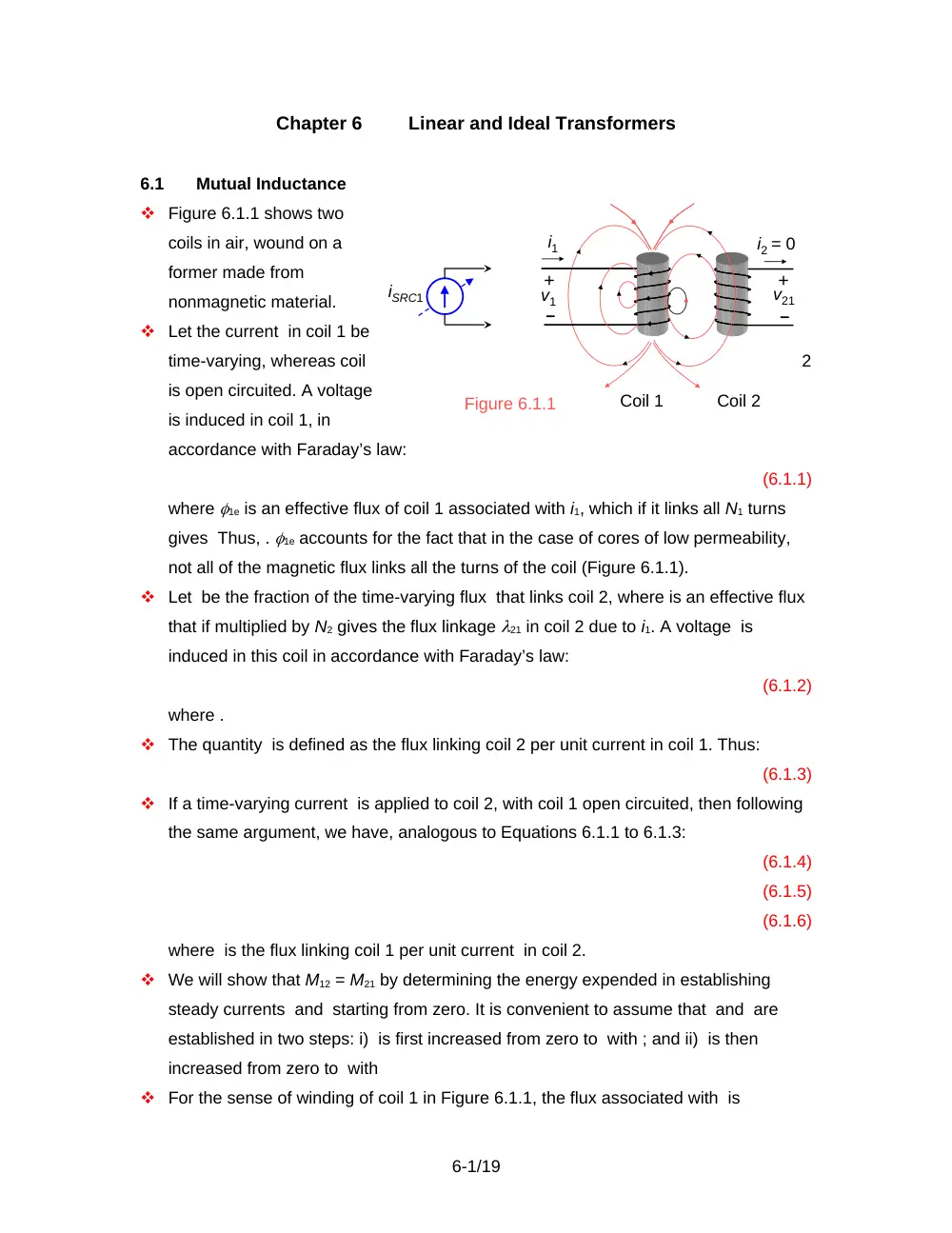
Figure 6.1.1 shows two
coils in air, wound on a
former made from
nonmagnetic material.
Let the current in coil 1 be
time-varying, whereas coil
2
is open circuited. A voltage
is induced in coil 1, in
accordance with Faraday’s law:
(6.1.1)
where 1e is an effective flux of coil 1 associated with i1, which if it links all N1 turns
gives Thus, . 1e accounts for the fact that in the case of cores of low permeability,
not all of the magnetic flux links all the turns of the coil (Figure 6.1.1).
Let be the fraction of the time-varying flux that links coil 2, where is an effective flux
that if multiplied by N2 gives the flux linkage 21 in coil 2 due to i1. A voltage is
induced in this coil in accordance with Faraday’s law:
(6.1.2)
where .
The quantity is defined as the flux linking coil 2 per unit current in coil 1. Thus:
(6.1.3)
If a time-varying current is applied to coil 2, with coil 1 open circuited, then following
the same argument, we have, analogous to Equations 6.1.1 to 6.1.3:
(6.1.4)
(6.1.5)
(6.1.6)
where is the flux linking coil 1 per unit current in coil 2.
We will show that M12 = M21 by determining the energy expended in establishing
steady currents and starting from zero. It is convenient to assume that and are
established in two steps: i) is first increased from zero to with ; and ii) is then
increased from zero to with
For the sense of winding of coil 1 in Figure 6.1.1, the flux associated with is
6-1/19
i1
+
–
v1
+
–
v21
i2 = 0
Figure 6.1.1
Coil 1
Coil 2
iSRC1
downward in this coil, according to the right-hand rule. While is increasing, the
induced voltage = in coil 1 opposes the increase in in accordance with Lenz’s law,
by being a voltage drop across L1 in the direction of i1. This voltage is concurrently a
voltage rise across the current source, so that the total energy delivered by the
source is:
(6.1.7)
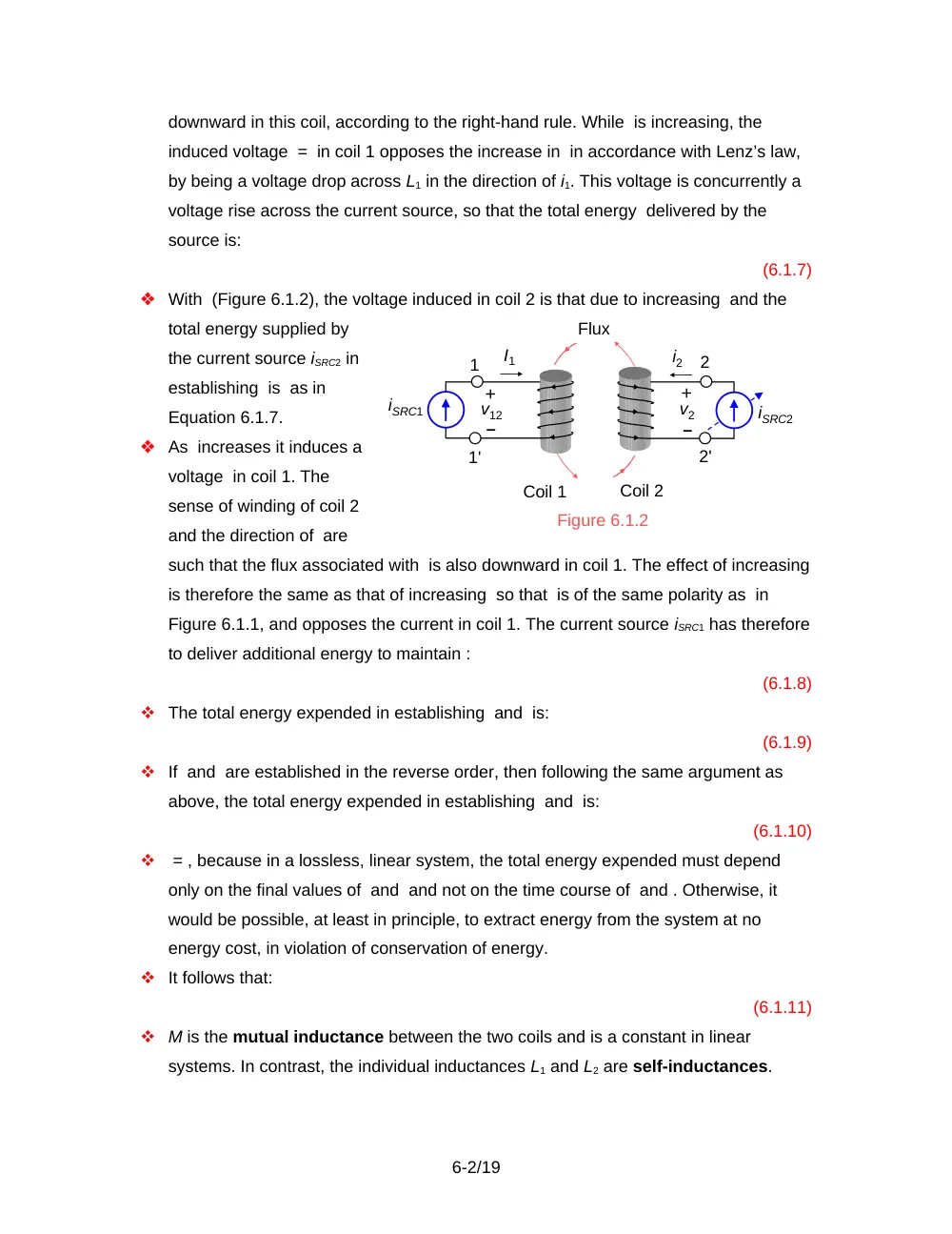
With (Figure 6.1.2), the voltage induced in coil 2 is that due to increasing and the
total energy supplied by
the current source iSRC2 in
establishing is as in
Equation 6.1.7.
As increases it induces a
voltage in coil 1. The
sense of winding of coil 2
and the direction of are
such that the flux associated with is also downward in coil 1. The effect of increasing
is therefore the same as that of increasing so that is of the same polarity as in
Figure 6.1.1, and opposes the current in coil 1. The current source iSRC1 has therefore
to deliver additional energy to maintain :
(6.1.8)
The total energy expended in establishing and is:
(6.1.9)
If and are established in the reverse order, then following the same argument as
above, the total energy expended in establishing and is:
(6.1.10)
= , because in a lossless, linear system, the total energy expended must depend
only on the final values of and and not on the time course of and . Otherwise, it
would be possible, at least in principle, to extract energy from the system at no
energy cost, in violation of conservation of energy.
It follows that:
(6.1.11)
M is the mutual inductance between the two coils and is a constant in linear
systems. In contrast, the individual inductances L1 and L2 are self-inductances.
6-2/19
Figure 6.1.2
I1
+
–
v12
+
–
v2
i2
Coil 1
Coil 2
Flux
iSRC2
1
1'
2
2'
iSRC1
Definition
The mutual inductance of two magnetically-coupled coils is the
flux linkage in one coil per unit current in the other coil. It is independent of
which coil carries the current.
If either the polarity of iSRC2, or the sense of winding of coil 2, is reversed in Figure
6.1.2, the flux due to becomes upward in coil 1. The polarity of is reversed and
becomes a voltage drop across the current source iSRC1. Energy is therefore returned
to the source and the sign of the energy term involving becomes negative in
Equations 6.1.9 and 6.1.10. M, however, is always a positive quantity.
Since and are arbitrary values, they might just as well be replaced by instantaneous
values and The energy stored in the magnetic field in building up the currents in two
magnetically coupled coils to i1 and i2, starting from zero, may therefore be
expressed in general as:
(6.1.12)
Coupling Through a High-Permeability Core
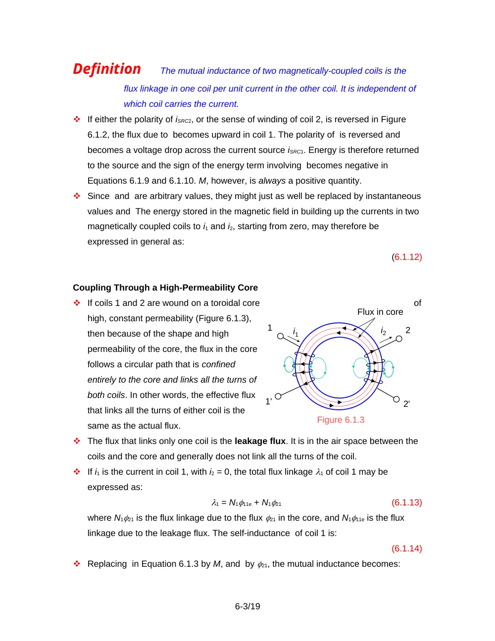
If coils 1 and 2 are wound on a toroidal core
of
high, constant permeability (Figure 6.1.3),
then because of the shape and high
permeability of the core, the flux in the core
follows a circular path that is confined
entirely to the core and links all the turns of
both coils. In other words, the effective flux
that links all the turns of either coil is the
same as the actual flux.
The flux that links only one coil is the leakage flux. It is in the air space between the
coils and the core and generally does not link all the turns of the coil.
If i1 is the current in coil 1, with i2 = 0, the total flux linkage 1 of coil 1 may be
expressed as:
1 = N111e + N121
(6.1.13)
where N121 is the flux linkage due to the flux 21 in the core, and N111e is the flux
linkage due to the leakage flux. The self-inductance of coil 1 is:
(6.1.14)
Replacing in Equation 6.1.3 by M, and by 21, the mutual inductance becomes:
6-3/19
Figure 6.1.3
i1
1'
1
Flux in core
i2
2'
2
(6.1.15)
If i2 is the current in coil 2, with i1 = 0, the relations corresponding to Equations 6.1.13
to 6.1.15 are obtained by repeating the above arguments. Thus:
2 = N222e + N212
(6.1.16)
(6.1.17)
(6.1.18)
Coupling Coefficient
Multiplying together Equations 6.1.15 and 6.1.18:
(6.1.19)
Dividing by the product L1L2 from Equations 6.1.14 and 6.1.17:
(6.1.20)
The expression is a measure of how effectively coil 1 is coupled to the core.
Similarly for . The product on the RHS of Equation 6.1.20 is a measure of how well
the two coils are magnetically coupled together through the core.
Equation 6.1.20 may be written as:
or
(6.1.21)
Definition
The coupling coefficient k of two magnetically-coupled coils is
defined as and is a measure of how tightly the two coils are coupled
through the core. It assumes values in the range of 0 to unity, where k = 0
denotes no coupling and k = 1 denotes perfect coupling.
Electric Circuit Analogy
A useful analogy can be
made between a
magnetic systems and
electric circuits (Table
6.1.1).
Magnetic flux is
analogous to electric
current, and
6-4/19
Table 6.1.1 Electric Circuit Analogy
Electric Circuit
Magnetic System
Current
Flux ()
Voltage excitation (emf)
mmf (Ni)
Resistance
Reluctance (mmf/flux)
Conductance
Permeance (flux/mmf)
Conductivity
Permeability
magnetomotive force (mmf), which equals Ni and drives magnetic flux, is analogous
to voltage excitation, also known as electromotive force (emf). Flux is the product of
permeance and mmf.
6.2
The Linear Transformer
Definition
A transformer consists of two or more coils that are magnetically
coupled relatively tightly. In a linear transformer, permeability is constant,
so that B and H, or and i, are linearly related.
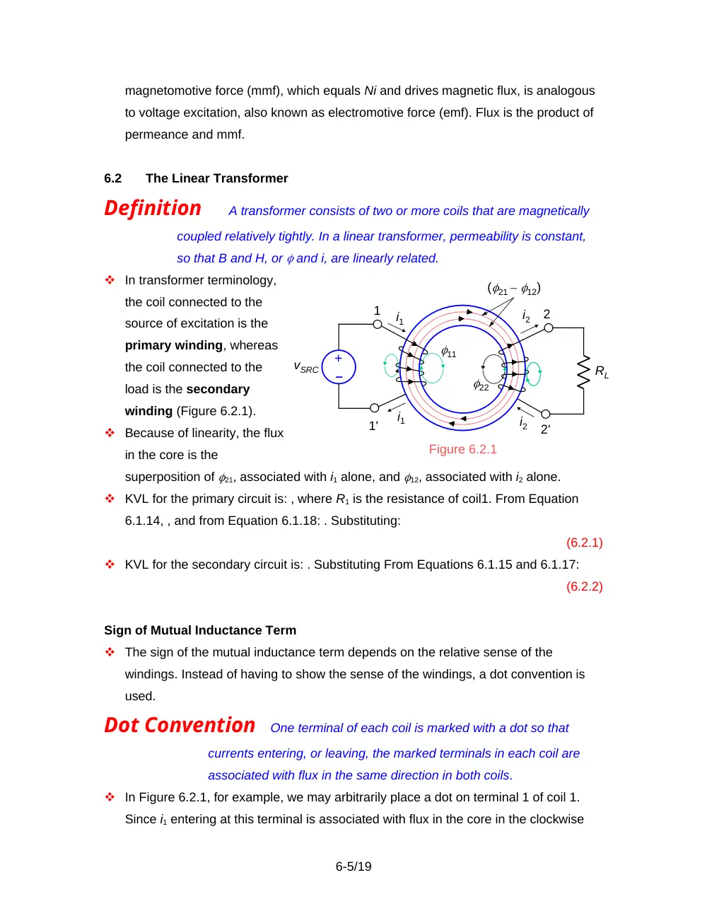
In transformer terminology,
the coil connected to the
source of excitation is the
primary winding, whereas
the coil connected to the
load is the secondary
winding (Figure 6.2.1).
Because of linearity, the flux
in the core is the
superposition of 21, associated with i1 alone, and 12, associated with i2 alone.
KVL for the primary circuit is: , where R1 is the resistance of coil1. From Equation
6.1.14, , and from Equation 6.1.18: . Substituting:
(6.2.1)
KVL for the secondary circuit is: . Substituting From Equations 6.1.15 and 6.1.17:
(6.2.2)
Sign of Mutual Inductance Term
The sign of the mutual inductance term depends on the relative sense of the
windings. Instead of having to show the sense of the windings, a dot convention is
used.
Dot Convention
One terminal of each coil is marked with a dot so that
currents entering, or leaving, the marked terminals in each coil are
associated with flux in the same direction in both coils.
In Figure 6.2.1, for example, we may arbitrarily place a dot on terminal 1 of coil 1.
Since i1 entering at this terminal is associated with flux in the core in the clockwise
6-5/19
Figure 6.2.1
–
+
vSRC
RL
i1
i2
i1
1'
1
(21 – 12)
i2
2'
2
11
22
direction, and i2 entering terminal 2 is also associated with flux in the same direction,
terminal 2 is dotted. Alternatively, terminals 1 and 2 may be dotted. If the sense of
winding of either coil is reversed, as in Figure 6.1.3, then the dotted terminals will be
1 and 2, or 1 and 2. In Figure 6.1.2, terminals 1 and 2, or 1 and 2, will be dotted.
An alternative interpretation of the dot markings, which follows from the above, is that
the polarities of induced voltages in both coils are the same, relative to the dot
markings. In Figure 6.1.2, when i2 is increasing, v2 opposes the increase in i2 and v12
opposes I1. Both voltages oppose currents entering at the dotted terminals, and the
polarities of these voltages make the dotted terminal positive with respect to the
unmarked terminal in both coils.
Once the terminals are marked with dots, the sign of the M term readily follows:
Sign of M Term
If the assigned positive directions of currents are
such that these currents both flow in, or both flow out, at the dotted
terminals, the sign of the mutual inductance term (Mdi1 /dt, or Mdi2 /dt)
for either coil is the same as that of the self-inductance term for that
coil (L1di1 /dt, or L2di2 /dt) . Otherwise, the sign of the mutual
inductance term for either coil is opposite that of the self-inductance
term for that coil.
The justification is that if the assigned positive directions of coil currents are such
that both currents flow into, or out of, the dotted terminals, and produce flux in the
same direction in the core. This means that the voltage induced by in coil 1 is of the
same polarity as the voltage induced by in coil 1, so that these two terms have the
same sign in the voltage relations of coil 1. Similarly for the voltage induced by in
coil 2 and the term.
Frequency-Domain Representation
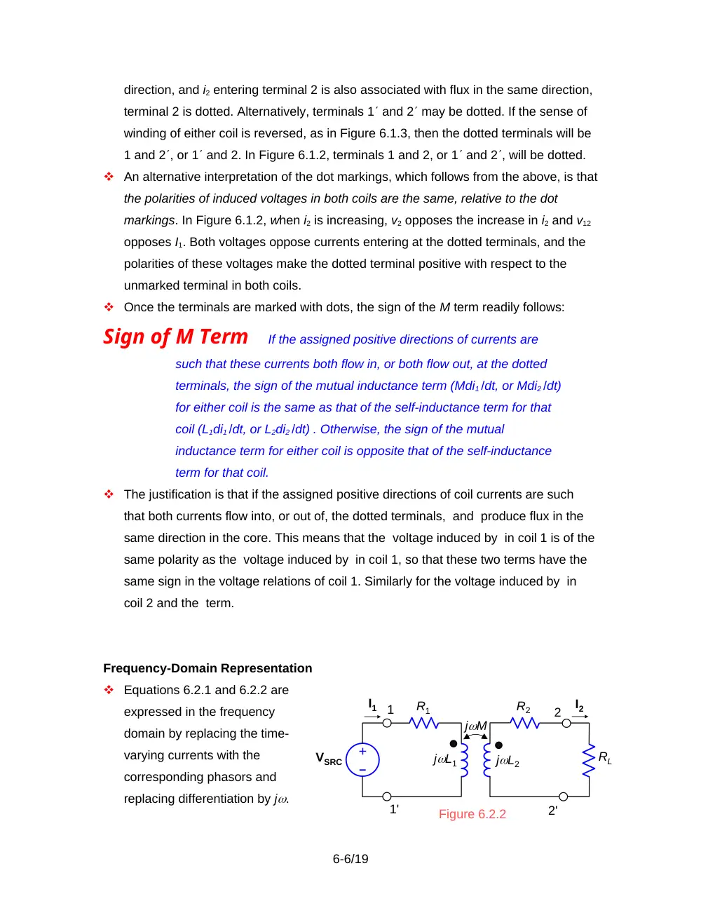
Equations 6.2.1 and 6.2.2 are
expressed in the frequency
domain by replacing the time-
varying currents with the
corresponding phasors and
replacing differentiation by j.
6-6/19
Figure 6.2.2
I2
VSRC
I1
–
+
RL
jL2
jL1
jM
R2
R1
1'
1
2'
2
(Figure 6.2.2). Thus:
I1 – jMI2 = VSRC
(6.2.3)
and,
-jMI1 + I2 = 0
(6.2.4)
T-Equivalent Circuit
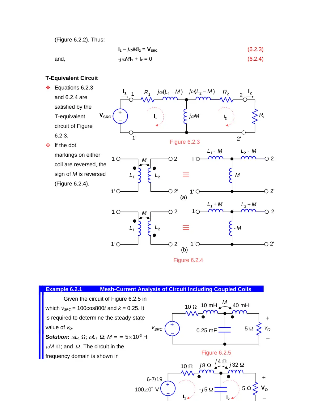
Equations 6.2.3
and 6.2.4 are
satisfied by the
T-equivalent
circuit of Figure
6.2.3.
If the dot
markings on either
coil are reversed, the
sign of M is reversed
(Figure 6.2.4).
Example 6.2.1
Mesh-Current Analysis of Circuit Including Coupled Coils
Given the circuit of Figure 6.2.5 in
which vSRC = 100cos800t and k = 0.25. It
is required to determine the steady-state
value of vO.
Solution: L1 ; L2 ; M 510-3 H;
M ; and . The circuit in the
frequency domain is shown in
6-7/19
Figure 6.2.3
I2
VSRC
I1
–
+
RL
jM
R2
R1
1'
1
2'
2
j(L1 – M )
j(L2 – M )
I2
I1
Figure 6.2.4
M
1'
1
2'
2
L1 M
L2 M
- M
1'
1
2'
2
L1 + M
L2 + M
L2
L1
M
1'
1
2'
2
L2
L1
M
1'
1
2'
2
(a)
(b)
10
M
+
_
vO
0.25 mF
vSRC
Figure 6.2.5
–
+
10 mH
40 mH
5
10
+
_
VO
1000 V
–
+
j 8
5
j 4 j 32
- j 5
I2
I1
Figure 6.2.6.
In writing the mesh current equation for mesh 1, the total voltage drop in this
mesh due to I1 equals, as usual, I1 multiplied by the total self-impedance of this mesh,
that is,(10 + j8 – j5)I1. I2 introduces as usual a voltage rise of ZcI2 in mesh 1, where Zc =-
j5 is the common impedance between meshes 1 and 2, plus a jMI2 term due to the
magnetic coupling between the coils in the two meshes. Since both I1 and I2 enter at the
dotted terminals, the sign of the jMI2 term is the same as that of jL1 term in the
equation of mesh 1 and the same as that of the jL2 term in the equation for mesh 2.
The mesh-current equation for mesh 1 is therefore:
(6.2.5)
Similarly, the mesh-current equation for mesh 2 is:
(6.2.6)
Solving for I2 gives: I2 = -
3.0636 – j0.5375 A, so that VO = 5I2
= -15.3 – j2.69 = 15.55-170.0 V, or
vO = 15.55cos(800t – 170.0) V.
Equations 6.2.5 and 6.2.6
could just as well be derived using
the T-equivalent circuit (Figure
6.2.7). If L1 in Figure 6.2.6a is
rotated clockwise and L2 is rotated
counterclockwise so as to bring them to the upright position, the dot markings will be as
in the transformer of Figure 6.2.4b. The appropriate T-equivalent circuit is therefore that
having series branches L1 + M and L2 + M and a shunt branch –M.
If the assigned positive direction of I2 in Figure 6.2.4 is made counterclockwise,
and this current is denoted by then flows into the unmarked terminal of coil 2. The sign
of the mutual inductance term is now opposite that of the self-inductance term for each
coil. The Zc term in the mutual impedance between the two meshes becomes positive
since the voltage drop due to flowing in Zc is also a voltage drop in mesh 1. Equations
6.2.5 and 6.2.6 become:
(6.2.7)
and,
(6.2.8)
Now = – I2 and Vo = –R2= R2I2 as before. The T-equivalent circuit is the same as
in Figure 6.4.6b.
6-8/19
Figure 6.2.7
10
+
_
VO
1000 V
–
+
j 12
5
j 36
- j 5
I2
I1
- j 4
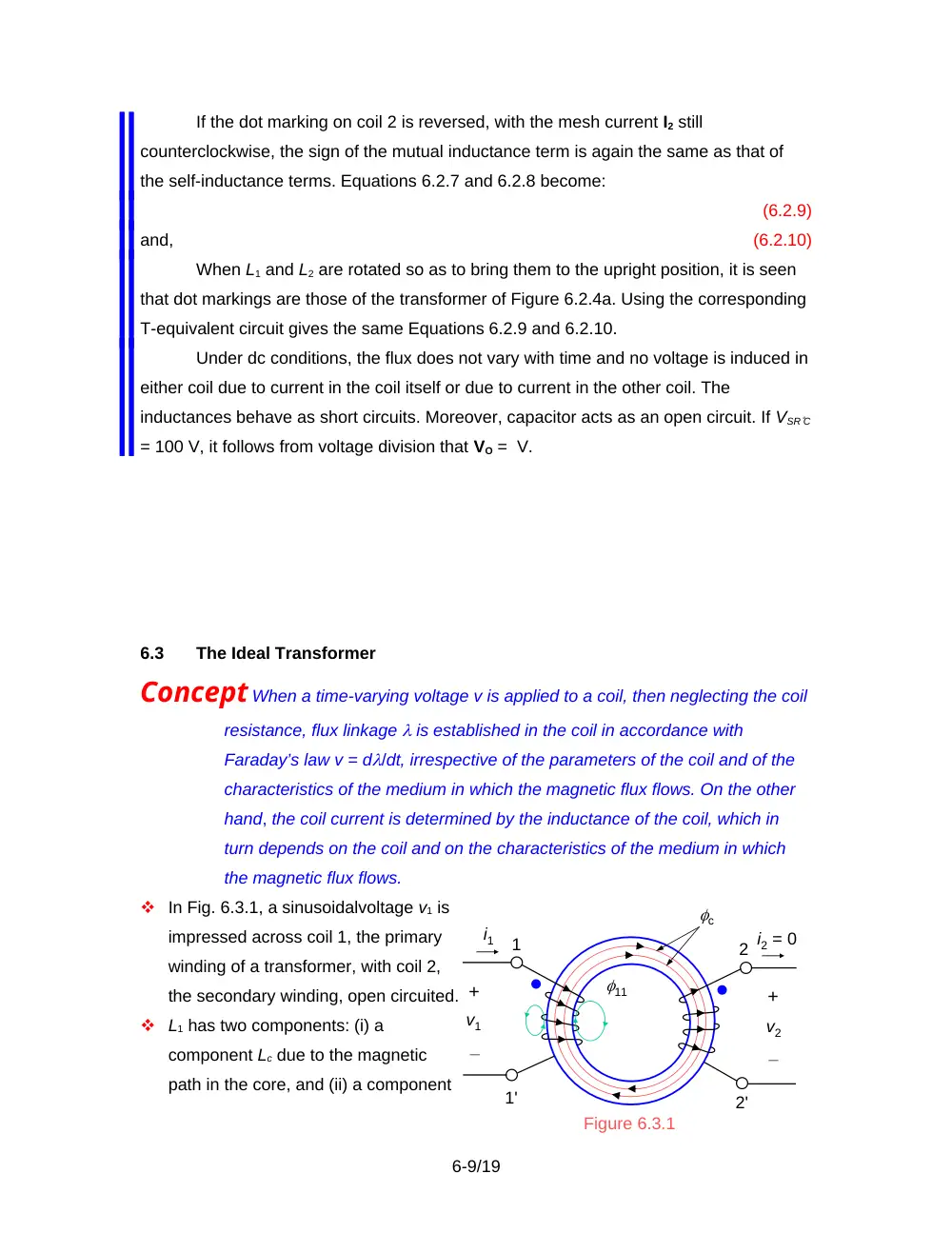
If the dot marking on coil 2 is reversed, with the mesh current I2 still
counterclockwise, the sign of the mutual inductance term is again the same as that of
the self-inductance terms. Equations 6.2.7 and 6.2.8 become:
(6.2.9)
and,
(6.2.10)
When L1 and L2 are rotated so as to bring them to the upright position, it is seen
that dot markings are those of the transformer of Figure 6.2.4a. Using the corresponding
T-equivalent circuit gives the same Equations 6.2.9 and 6.2.10.
Under dc conditions, the flux does not vary with time and no voltage is induced in
either coil due to current in the coil itself or due to current in the other coil. The
inductances behave as short circuits. Moreover, capacitor acts as an open circuit. If VSRC
= 100 V, it follows from voltage division that VO = V.
6.3
The Ideal Transformer
Concept When a time-varying voltage v is applied to a coil, then neglecting the coil
resistance, flux linkage is established in the coil in accordance with
Faraday’s law v = d/dt, irrespective of the parameters of the coil and of the
characteristics of the medium in which the magnetic flux flows. On the other
hand, the coil current is determined by the inductance of the coil, which in
turn depends on the coil and on the characteristics of the medium in which
the magnetic flux flows.
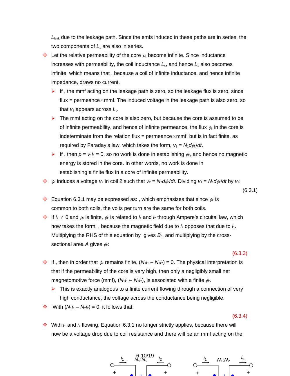
In Fig. 6.3.1, a sinusoidalvoltage v1 is
impressed across coil 1, the primary
winding of a transformer, with coil 2,
the secondary winding, open circuited.
L1 has two components: (i) a
component Lc due to the magnetic
path in the core, and (ii) a component
6-9/19
Figure 6.3.1
v1
i1
1'
1
c
2'
2
11
i2 = 0
+
_
+
_
v2
Lleak due to the leakage path. Since the emfs induced in these paths are in series, the
two components of L1 are also in series.
Let the relative permeability of the core r become infinite. Since inductance
increases with permeability, the coil inductance Lc, and hence L1 also becomes
infinite, which means that , because a coil of infinite inductance, and hence infinite
impedance, draws no current.
If , the mmf acting on the leakage path is zero, so the leakage flux is zero, since
flux = permeancemmf. The induced voltage in the leakage path is also zero, so
that v1 appears across Lc.
The mmf acting on the core is also zero, but because the core is assumed to be
of infinite permeability, and hence of infinite permeance, the flux c in the core is
indeterminate from the relation flux = permeancemmf, but is in fact finite, as
required by Faraday’s law, which takes the form, v1 = N1dc/dt.
If , then p = v1i1 = 0, so no work is done in establishing c, and hence no magnetic
energy is stored in the core. In other words, no work is done in
establishing a finite flux in a core of infinite permeability.
c induces a voltage v2 in coil 2 such that v2 = N2dc/dt. Dividing v1 = N1dc/dt by v2:
(6.3.1)
Equation 6.3.1 may be expressed as: , which emphasizes that since c is
common to both coils, the volts per turn are the same for both coils.
If i2 0 and r is finite, c is related to i1 and i2 through Ampere’s circuital law, which
now takes the form: , because the magnetic field due to i2 opposes that due to i1.
Multiplying the RHS of this equation by gives Bc, and multiplying by the cross-
sectional area A gives c:
(6.3.3)
If , then in order that c remains finite, (N1i1 – N2i2) = 0. The physical interpretation is
that if the permeability of the core is very high, then only a negligibly small net
magnetomotive force (mmf), (N1i1 – N2i2), is associated with a finite c.
This is exactly analogous to a finite current flowing through a connection of very
high conductance, the voltage across the conductance being negligible.
With (N1i1 – N2i2) = 0, it follows that:
(6.3.4)
With i1 and i2 flowing, Equation 6.3.1 no longer strictly applies, because there will
now be a voltage drop due to coil resistance and there will be an mmf acting on the
6-10/19
i1
i2
+
+
i1
i2
+
+
N1:N2
N1:N2
leakage path to produce a leakage flux and hence a voltage drop. Thus, in order that
both Equations 6.3.1 and 6.3.4 apply, we have to assume negligible resistance and
perfect coupling between the coils and the core.
If the assigned positive
direction of and do not
conform to the dot
markings . Similarly, if
and both enter or leave
at the dotted terminals,
so that . The four
possibilities are
illustrated in Figure 6.3.2.
It follows from the voltage and current ratios that the instantaneous power input
equals the instantaneous power output, neglecting power losses in the core.
Definition
An ideal transformer is a two-port device that neither dissipates
nor stores energy, and whose input-output v-i relations are of the form: and
From Equation 1.9.8: and , so that:
(6.3.5)
independently of r. Thus, although each of L1 and L2 becomes infinite as r becomes
infinite, their ratio remains finite and equal to the square of the turns ratio.
Phasor Relations
Figure 6.3.3b shows the phasor diagram for the ideal transformer of Figure 6.3.3a.
Figure 6.3.3c is a flow diagram of the causal relationships.
A voltage V1 applied to the primary winding establishes a flux c in the core such that
c V1 and lags V1 by 90. c induces a voltage V2 in the secondary winding such that
V2c, assuming the assigned positive directions and dot markings shown. Since V2
leads c by 90, it is in phase with V1. V2 causes a current I2 in the
secondary circuit,
which lags V2 by an
angle , assuming ZL
is inductive. In order
to have zero mmf in
6-11/19
2
1
2
1
N
N
v
v
1
2
2
1
N
N
i
i
2
1
2
1
N
N
v
v
1
2
2
1
N
N
i
i
(c)
(d)
Figure 6.3.2
i1
i2
v2
_
+
v1
_
+
i1
i2
v2
_
+
v1
_
+
N1:N2
N1:N2
V1
1/jN1
c
jN2
1/ZL
V1
ZL
+
_
V2
_
+
I1
I2
V1
V2
I2
I1
c
(a)
(b)
(c)
N1:N2
N1I1 – N2I2 = 0
I2
V2
I1
the core, a current I1 flows in the primary winding such that I1I2.
Reflected Impedance
For the dot markings and assigned positive directions of Figure 6.3.3a: and .
Dividing these two equations: . Substituting :
(6.3.6)
Because of squaring of the turns ratio, Equation 6.3.6 is valid for any of the
configurations of Figure 6.3.3a to d.
An open circuit is reflected as an open circuit, and a short circuit is reflected as a
short circuit.
Example 6.3.1
Ideal Transformer Circuit
Assume that in Figure 6.3.4, v1 = 120cos1000t,
N1:N2 = 1:2, and that Z consists of a resistance of 10
in series with a 20 mH inductor. It is required to
determine the primary current and the secondary
current and voltage.
Solution: V2 = V1 = 2400 V; hence I2 =
-63.4 A. It follows that I1 = I2 -63.4 A.
The Ideal Autotransformer
Consider a two-winding transformer having
(Figure 6.3.5a). v1 can be stepped up to v2 by
adding to v1 a voltage , resulting in a step-up
autotransformer (Figure 6.3.5b).
A winding of is required, and the
current in the common winding is i1 –
i2, which means that this winding can
have a conductor of smaller cross-
sectional area. Both of these
considerations make the
autotransformer smaller and lighter. In
addition, terminal a in Figure 6.3.5b
6-12/19
V1
+
_
V2
_
+
I1
I2
Figure 6.3.4
N1:N2
10
j 20
i1
i2
+
_
v2
Load
c
v1
(a)
N1
N2
+
_
d
a
b
2
N
1
N
i1 – i2
i2
+
_
+
_
v2
Load
a
b
d
i1
(b)
Figure 6.3.5
v1
+
_
2
v
could be connected to a slider over a bare part of the winding, so that a variable
turns ratio is obtained.
The principal disadvantage of the autotransformer is that the input and output sides
are not electrically isolated, because of the conduction path between them.
The voltage and current relations for the autotransformer follow directly from those of
the two-winding transformer by substituting . Thus:
(6.3.8)
(6.3.9)
If the dot marking on either winding is reversed, the effective turns ratio becomes .
Example 6.3.2
Three-Winding Transformer
Given a three-winding ideal
transformer with loads Z2 and Z3
connected as shown in Figure 6.3.7. It is
required to determine the input
impedance.
Solution: Method 1: Since the voltage
induced per turn is the same for all
windings, , and
, where the assigned positive directions
of V1, V2, and V3 are all in accordance
with the dots, so that the volts per turn
are positive for all the windings. Since the net mmf in the core must be zero,
= 0, where and . Note that I1 and (I1 – I2) enter at the dotted terminals of their respective
windings. Their mmfs are in the same sense and may be assigned a positive sign. I3
leaves its winding at the dotted terminals, so its mmf is assigned a negative sign.
Eliminating , , , and from these equations gives:
(6.3.10)
If , the impedance reflected to the primary side is , as for a two-winding
transformer of turns ratio . If , the reflected impedance is , as for an autotransformer of
turns N1 and N2. In fact, these reflected impedances in parallel give the reflected
impedance of Equation 6.3.10.
6-13/19
+
Z2
I2
I1
I3
Z3
+
V3
N2
I1 I2
+
V1
V2
Figure 6.3.7
1
N
_
_
N3
_
Method 2: Let the impedances be
replaced by current sources I2 and
I3, in accordance with the
substitution theorem, as shown in
Figure 6.3.8, where and . We now
apply superposition. If is applied
alone, the primary current is . If is
applied alone, the primary current
is . With both sources applied, the
primary current is I1 = + .
Substituting for the currents in
terms of voltages and impedances: I1 = + . But = V1 and =V1. Substituting for and gives:
I1 = V1. The reflected impedance V1
/ I1 is the same as that obtained above.
Note that superposition strictly applies to voltage sources and current sources
only. It cannot be applied directly to impedances, such as Z2 and Z3 in this Example.
However, the substitution theorem allowed us to apply superposition after replacing
these impedances with sources.
6.4
Reflection of Circuits
Concept Circuits involving ideal transformers can be conveniently analyzed by
reflecting the circuit on the primary side to the secondary side, or conversely.
Consider Figure 6.4.1.
KCL for node q is:
I2 + IL(V2 – Vy)
(6.4.1)
6-14/19
_
+
+ _
VSRC
Vy
+
_
V1
V2
I1
I2
ISRC
Ix
IL
Zsrc
ZL
p
q
1:a
Primary side
Secondary side
+
_
Figure 6.4.1
I2
I1
I3
+
V3
N2
+
V1
V2
Figure 6.3.8
_
N3
_
–
+
N1
Substituting: V2 = aV1 and I2I1, Equation 6.4.1 may be expressed as:
I1IL
(6.4.2)
where .
This is KCL
for a node q′
in Figure
6.4.2. The
voltage V1 at
node p and
the current I1
leaving this
node, are unaltered. The ideal transformer now appears at the extreme right with its
secondary open-circuited. Since it is not serving any useful function, it can be
omitted from the circuit.
In Figure 6.4.2, the secondary circuit is reflected to the primary side, element by
element. If a > 1, voltages are stepped down by a and currents are stepped up by a.
Impedances are stepped down, like voltages, but by a factor a2.
In a similar manner, we may write KCL for node p in Figure 6.4.1 as:
(6.4.3)
Substituting: and , Equation 6.4.3 may be expressed as:
(6.4.4)
where . This is KCL
for a node p′ on the
secondary side in
Figure 6.4.3. The
voltage and currents
at node q are
unaltered. The ideal
transformer now appears at the extreme left of the figure with its primary open-
circuited. Since it is not serving any useful function, it can be omitted from the circuit.
In reflecting circuits from one side to the other, the order of the elements, left to right
or right to left, must be preserved. Otherwise, the circuit is altered.
Controlling currents or voltages of dependent sources are reflected like any other
voltage or current.
6-15/19
aVSRC
Vy
+
V2
I2
ISRC /a
Ix /a
IL
a2Zsrc
p
q
ZL
1:a
+ _
+
_
_
Figure 6.4.3
VSRC
Vy /a
+
V1
I1
ISRC
Ix
aIL
Zsrc
p
q
1:a
2
a
Z L
+ _
+
_
_
Figure 6.4.2
When the dot markings are reversed, a negative value of a is used.
6.5
Transformer Imperfections
Practical transformers depart from the ideal in the following respects:
finite inductance of the windings;
finite leakage flux;
power losses, because of finite resistance of the windings and core losses;
capacitances between primary and secondary windings as well as between
layers of the same winding. The capacitances arise because of voltage
differences and consequent energy storage in the electric field.
The finite resistances of the windings are accounted for, at least at low frequencies,
by adding them at the terminals of the respective winding
The distributed capacitance between windings and layers of the same winding are
accounted for in an approximate manner by lumped capacitances connected across
the terminals of the primary and secondary windings and between these windings.
Ignoring the aforementioned imperfections, except for finite inductances and
imperfect coupling, we are left with a linear transformer consisting of two coupled,
lossless coils, of inductances L1 and L2 (Figure 6.5.1).
The governing equations are Equations 6.2.3 and 6.2.4, with R1 = 0 = R2, and with RL
replaced by ZL:
I1 – jMI2 = VSRC
(6.5.1)
-jMI1 + I2 = 0
(6.5.2)
Any circuit that represents the effect of
finite inductances of windings and finite
leakage fluxes must satisfy these
equations.
Finite Inductance of Windings
Let the coils to be perfectly coupled to begin with, that is, . Substituting for I2 from
Equation 6.5.2 in Equation 6.5.1:
(6.5.3)
With , it follows that the impedance
seen by the source is that of jL2 in
parallel with ZL, reflected to the primary
6-16/19
I2
I1
I2
VSRC
I1
–
+
Inductance ratio
L1:L2
(a)
jL2
1'
1
2'
2
ZL
Figure 6.5.1
I2
VSRC
I1
–
+
ZL
jL2
jL1
jM
1'
1
2'
2
side of an ideal transformer having an inductance ratio of L1:L2, or a turns ratio
(Equation 6.3.5), as illustrated in Figure 6.5.2a. The impedance jL2 reflected to the
primary side becomes jL1 (Figure 6.5.2b).
It is seen that the effect of finite inductances of an otherwise ideal transformer is to
introduce a shunt impedance jL1 on the primary side, or a shunt impedance jL2 on
the secondary side.
Finite Leakage flux
Because equivalence must apply for any value of ZL, we may assume that ZL = 0.
Substituting in Equation 6.5.3:
(6.5.4)
When terminals 22 in Figure 6.5.2b are short circuited by having ZL = 0, jL1 is short
circuited. To satisfy Equation 6.5.4,
a series impedance must be
inserted in series at terminal 1, as
shown in Figure 6.5.3.
When terminals 22 are open
circuited, I2 = 0, and Equation 6.5.1
gives: . To satisfy this condition,
the shunt impedance must be instead of , as
shown. Moreover, L2 in Figure 6.5.2a must now be reflected as k2L1 in order to satisfy
this same condition, which implies that the inductance ratio is k2L1:L2.
Concept The performance of a transformer is limited at low frequencies by the
reactance of the windings and at high frequencies by the leakage reactance.
At low frequencies, the leakage impedance is negligible, but the impedance jL2
appears in parallel with ZL. If the transformer is not to affect adversely the behavior of
the circuit, jL2 >> ZL.
At high frequencies, the shunting effect of jL2 can be neglected. The leakage
impedance referred to the secondary side becomes and appears in series with the
6-17/19
jk2L1
Inductance ratio
k2L1:L2
j(1-k2)L1
Figure 6.5.3
VSRC
I1
–
+
1'
1
I2
2'
2
ZL
load. If the transformer is not to affect adversely the
behavior of the circuit, this impedance should be small compared with ZL.
Core Losses
These are of two types: eddy-current losses and hysteresis losses.
Eddy-current losses occur in any core made of electrically conducting material.
Suppose that the secondary in Figure 6.3.1 consists of a single, closed turn of wire of
resistance R. A voltage of rms value is induced in this turn and causes a current ,
assuming the inductance of the turn is negligible with respect to its resistance The
power loss is /R.
But a similar situation occurs
throughout the body of the core,
since any closed path inside the
core may be considered to act
like the closed turn of wire, as
illustrated in Figure 6.5.4a.
This causes eddy currents to
circulate in the core. Apart from
the power loss and the resultant
heating, the flux of these eddy
currents (e (t) in Figure 6.5.4a
opposes, and hence decreases,
the flux in the core.
To reduce these currents, either a magnetic material of high resistivity is used, or the
core is made of thin laminations that are insulated from one another and stacked
together so that the flux is in a direction parallel to the plane of the laminations
(Figure 6.5.4b). The induced currents are confined by the insulation to within each
lamination. This effectively reduces the cross sectional area of the loop that encloses
flux and which can give rise to current flow.
Iron, steel, nickel, cobalt and their alloys are ferromagnetic materials, characterized
by high permeability and nonlinearity that includes hysteresis. In general, hysteresis
arises when an effect lags behind its cause. As a result, the state of a system
6-18/19
c(t)
e (t)
Eddy current
I
c(t)
Cross
section
Cross
section
Laminated Core