
EECE 210 Chapter 5, Fall 2012
American University of Beirut · Electric Circuits · 13 pages


Showing the first 10 of 13 pages. Download the PDF to see all of it.
More EECE 210 files
- Chapter Uploading Chapter 08 Sinusoidal Steady · Spring 2015ChapterView
- Homework All Chapters · Fall 2015ChapterView
- Chapter 1 · Fall 2012ChapterView
- Chapter 2 · Fall 2012ChapterView
- Chapter 3 · Fall 2012ChapterView
- Chapter 4 · Fall 2012ChapterView
- Chapter 6 · Fall 2012ChapterView
- Chapter 7 · Fall 2012ChapterView
Show the text of this chapter
Chapter 5
Sinusoidal Steady State
5.1
Sinusoidal Function
(5.1.1)
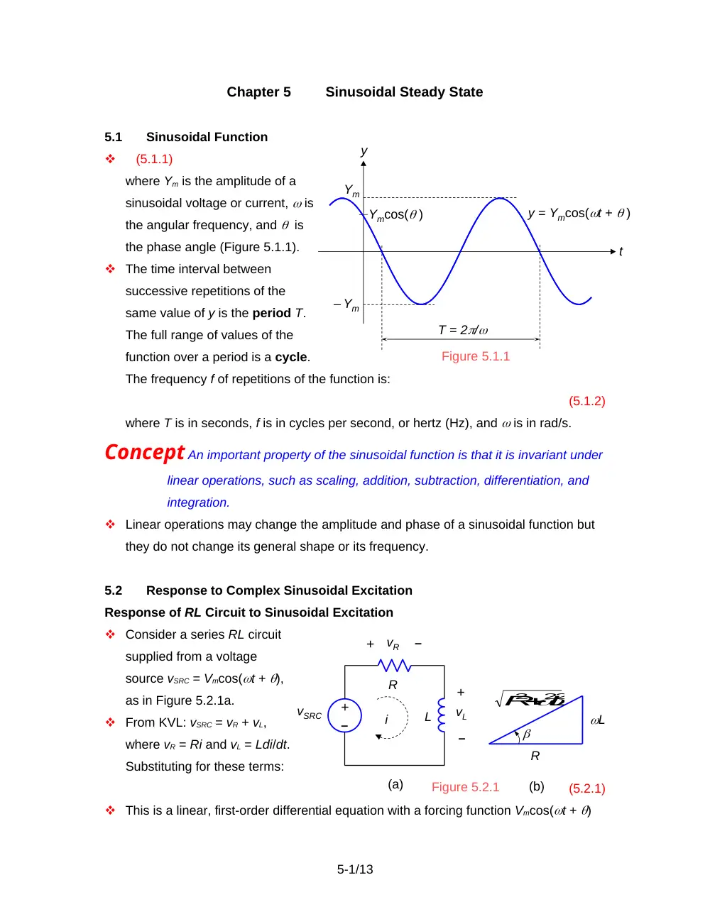
where Ym is the amplitude of a
sinusoidal voltage or current, is
the angular frequency, and is
the phase angle (Figure 5.1.1).
The time interval between
successive repetitions of the
same value of y is the period T.
The full range of values of the
function over a period is a cycle.
The frequency f of repetitions of the function is:
(5.1.2)
where T is in seconds, f is in cycles per second, or hertz (Hz), and is in rad/s.
Concept An important property of the sinusoidal function is that it is invariant under
linear operations, such as scaling, addition, subtraction, differentiation, and
integration.
Linear operations may change the amplitude and phase of a sinusoidal function but
they do not change its general shape or its frequency.
5.2
Response to Complex Sinusoidal Excitation
Response of RL Circuit to Sinusoidal Excitation
Consider a series RL circuit
supplied from a voltage
source vSRC = Vmcos(t + ),
as in Figure 5.2.1a.
From KVL: vSRC = vR + vL,
where vR = Ri and vL = Ldi/dt.
Substituting for these terms:
(5.2.1)
This is a linear, first-order differential equation with a forcing function Vmcos(t + )
5-1/13
y
Ym
T = 2/
Ymcos( )
Figure 5.1.1
– Ym
t
y = Ymcos(t + )
vSRC
R
L
i
L
R
(a)
(b)
Figure 5.2.1
2
2 2
L
R
–
+
+
+
–
–
vR
vL
on the RHS. The complete solution is the sum of two components:
A transient component that is the solution to the equation , and which dies out
with time. A steady state is assumed to prevail only after the transient component
has become insignificant.
A steady-state component iSS that satisfies Equation 5.2.1. Since the linear
operations on the LHS of Equation 5.2.1 affect the amplitude and phase of iSS
without affecting the frequency. we may consider iSS to be of the form:
(5.2.2)
where Im and are unknowns to be determined so as to satisfy Equation 5.2.1.
Substituting iSS from Equation 5.2.2 in Equation 5.2.1:
(5.2.3)
If the LHS of Equation 5.2.3 is multiplied and divided by , it becomes:
(5.2.4)
Let be the angle whose sine is and whose cosine is therefore (Figure 5.2.1b).
Equation 5.2.4 becomes:
or:
(5.2.5)
To equalize both sides of Equation 5.2.5 under all conditions, we must have and =
. It follows that:
,
(5.2.6)
Response of RL Circuit to Complex Sinusoidal Excitation
Let:
(5.2.7)
Since the circuit is linear, superposition applies, and iSS = iSS1 + iSS2, where iSS1 is the
steady-state response to Vmcos(t + ), as given by Equation 5.2.6, and iSS2 is the
steady-state response to jVmsin(t + ).
The excitation jVmsin(t + ) may be written as . Hence, iSS2 can be obtained from iss1
by replacing by ( –) and multiplying Vm by j. This gives:
,
(5.2.8)
5-2/13
Concept When a complex sinusoidal excitation vSRC is applied to an LTI circuit, the
response is a complex sinusoidal function whose real part is the response to
the real part of the excitation, Vmcos(t + ), applied alone, and whose
imaginary part is the response to the imaginary part of the excitation, Vmsin(t
+ ), applied alone.
In other words, the real and imaginary parts retain their separate identities in linear
operations, without any mutual interaction.
5.3
Phasor Notation
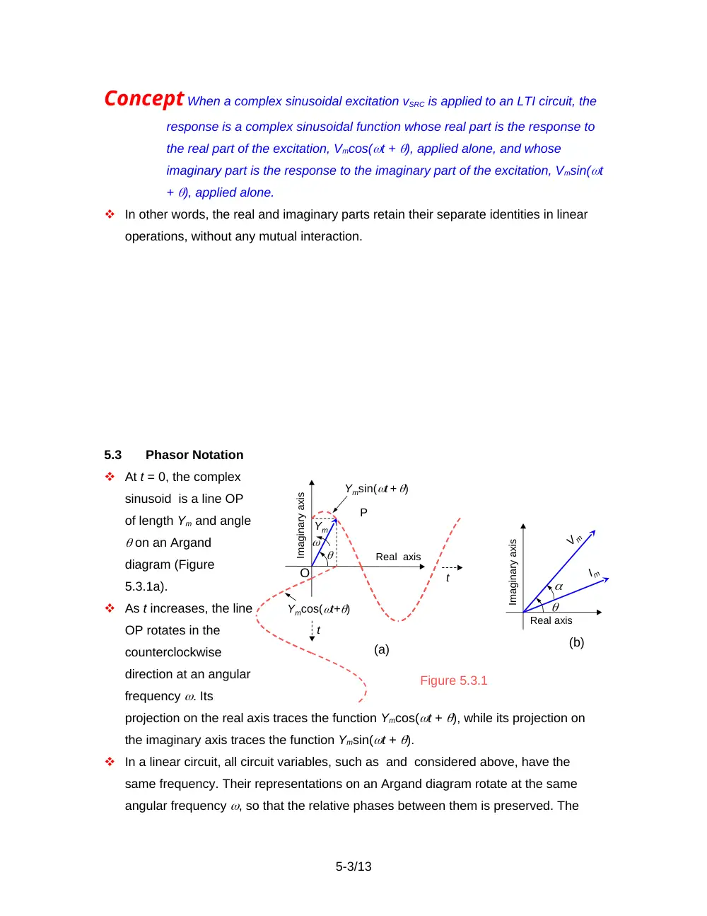
At t = 0, the complex
sinusoid is a line OP
of length Ym and angle
on an Argand
diagram (Figure
5.3.1a).
As t increases, the line
OP rotates in the
counterclockwise
direction at an angular
frequency . Its
projection on the real axis traces the function Ymcos(t + ), while its projection on
the imaginary axis traces the function Ymsin(t + ).
In a linear circuit, all circuit variables, such as and considered above, have the
same frequency. Their representations on an Argand diagram rotate at the same
angular frequency , so that the relative phases between them is preserved. The
5-3/13
Figure 5.3.1
Imaginary axis
Real axis
Vm
Im
(a)
(b)
P
Ym
t
t
Ymsin(t + )
Ymcos(t+)
O
Real axis
Imaginary axis
rotation can be frozen at t = 0 without loss of the information contained in the
magnitudes and relative phase angles (Figure 5.3.1b).
Definition
A phasor is a quantity such as or representing a complex
sinusoidal function of time, but with the time variation suppressed.
Phasors are written in boldface and expressed as a magnitude and phase angle:
V
(5.3.1)
Properties of Phasors
Since phasors have magnitude and direction, they are similar to vectors in many
respects, but have a real part, Yr = Ymcos, and an imaginary part, Yi = Ymsin. It
follows that .
Multiplying a phasor by a real quantity K multiplies its magnitude by K, without
changing its phase angle.
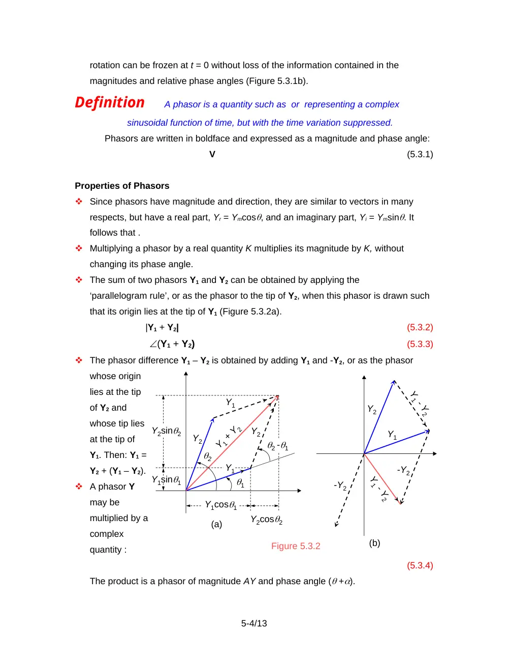
The sum of two phasors Y1 and Y2 can be obtained by applying the
‘parallelogram rule’, or as the phasor to the tip of Y2, when this phasor is drawn such
that its origin lies at the tip of Y1 (Figure 5.3.2a).
|Y1 + Y2|
(5.3.2)
(Y1 + Y2)
(5.3.3)
The phasor difference Y1 – Y2 is obtained by adding Y1 and -Y2, or as the phasor
whose origin
lies at the tip
of Y2 and
whose tip lies
at the tip of
Y1. Then: Y1 =
Y2 + (Y1 – Y2).
A phasor Y
may be
multiplied by a
complex
quantity :
(5.3.4)
The product is a phasor of magnitude AY and phase angle ( +).
5-4/13
Figure 5.3.2
(a)
(b)
1
2
2 -1
Y1
Y1
Y2
Y2
Y1 + Y2
Y1cos1
Y2cos2
Y2sin2
Y1sin1
Y2
-Y2
Y1
-Y2
Y1 - Y2
Y1 - Y2
A phasor Y may be divided by a complex quantity :
(5.3.5)
The quotient is a phasor of magnitude and phase angle ( –).
In the complex plane, j is an imaginary quantity of unit magnitude and a phase angle
of /2:
(5.3.6)
Multiplying a phasor by j rotates the phasor through an angle /2
counterclockwise without changing its magnitude. Dividing a phasor by j, or
conversely multiplying it by –j, since , rotates the phasor through an angle /2
clockwise without changing its magnitude.
Example 5.3.1
Magnitude, Real Part, and Imaginary Part of a Complex
Fraction
It is required to determine the magnitude, real, and imaginary parts of .
Solution: Let us rationalize Y, i.e., make its denominator real, by multiplying numerator
and denominator by the complex conjugate of the denominator, c – jd. Thus:
(5.3.7)
The real part of Y is its imaginary part is.
The magnitude of Y may be obtained as the square root of the sum of the
squares of the real and imaginary parts. An easier way is to convert the numerator and
denominator to polar coordinates. Thus: . The magnitude of Y is therefore . It should be
noted that, whereas the magnitude of Y is the magnitude of the numerator divided by
that of the denominator, the real part of Y is not the real part of the numerator divided by
that of the denominator. Nor is the imaginary part of Y the imaginary part of the
numerator divided by that of the denominator.
5.4
Phasor Relations of Circuit Elements
Phasor Relations for a Resistor
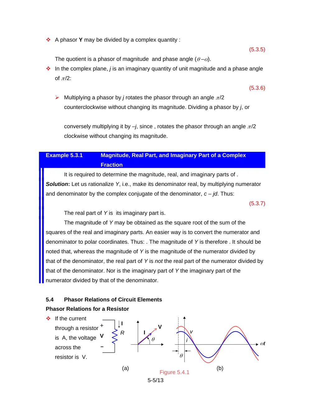
If the current
through a resistor
is A, the voltage
across the
resistor is V.
5-5/13
V
+
R
I
(a)
i
t
v
(b)
Figure 5.4.1
V
I
–
In phasor notation (Figure 5.4.1a):
VI, or
IV
(5.4.1)
According to the interpretation of complex sinusoidal excitation, a voltage Vmcos(t +
) V produces a current A that is in phase (Figure 5.4.1b).
The energy dissipated in a resistor R over a period is:
(5.4.2)
The average power dissipated is:
(5.4.3)
The operations leading to Equation 5.4.3 involve squaring the current Imcos(t + ),
then taking the mean value over a period, which is . Similarly, the mean square of
the voltage is . The square roots of these quantities are the root-mean-square
(rms), values. Thus:
,
and
(5.4.4)
The power dissipated may be expressed in terms of rms values as:
W
(5.4.5)
Since the power dissipated in R by a dc current I is W, it follows that:
Concept A current of rms value Irms, or a voltage of rms value Vrms, dissipate the
same power in a given resistor as a dc current, or a dc voltage, of the same
value.
Phasor Relations for an Inductor
If the inductor current is A, the inductor voltage is:
V
(5.4.6)
In phasor notation, I A, and V V, or:
VI,
or
IV
(5.4.7)
The magnitude of V is L times that of I, and the phase angle of V is /2 plus the
phase
angle
of I
(Figure
5.4.2a).
5-6/13
jL
(a)
(b)
I
V
Im
Vm
V
+
I
–
Figure 5.4.2
i
t
v
Q
P
According to the interpretation of complex sinusoidal excitation, if the inductor current
is: A, the inductor voltage is: V. The voltage leads the current by 90, or the current
lags the voltage by 90 (Figure 5.4.2b).
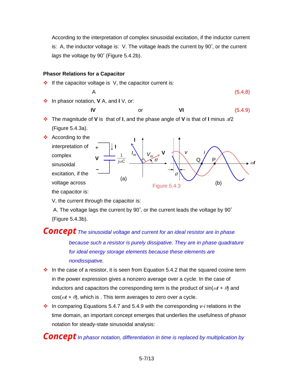
Phasor Relations for a Capacitor
If the capacitor voltage is V, the capacitor current is:
A
(5.4.8)
In phasor notation, V A, and I V, or:
IV
or
VI
(5.4.9)
The magnitude of V is that of I, and the phase angle of V is that of I minus /2
(Figure 5.4.3a).
According to the
interpretation of
complex
sinusoidal
excitation, if the
voltage across
the capacitor is:
V, the current through the capacitor is:
A. The voltage lags the current by 90, or the current leads the voltage by 90
(Figure 5.4.3b).
Concept The sinusoidal voltage and current for an ideal resistor are in phase
because such a resistor is purely dissipative. They are in phase quadrature
for ideal energy storage elements because these elements are
nondissipative.
In the case of a resistor, it is seen from Equation 5.4.2 that the squared cosine term
in the power expression gives a nonzero average over a cycle. In the case of
inductors and capacitors the corresponding term is the product of sin(t + ) and
cos(t + ), which is . This term averages to zero over a cycle.
In comparing Equations 5.4.7 and 5.4.9 with the corresponding v-i relations in the
time domain, an important concept emerges that underlies the usefulness of phasor
notation for steady-state sinusoidal analysis:
Concept In phasor notation, differentiation in time is replaced by multiplication by
5-7/13
(a)
I
V
Vm
Im
C
j
1
I
V
+
–
Figure 5.4.3
i
t
v
Q
P
(b)
j, and integration in time is replaced by division by j. Thus, differential and
integral relations are transformed to algebraic relations in j for steady-state
sinusoidal analysis ONLY.
5.5
Impedance and Reactance
Let be a voltage phasor and be a related current phasor, representing, for example,
the voltage and current between any two nodes in a circuit, and let . Then:
Definition
Impedance Z is the ratio of the voltage phasor to the related
current phasor :
= Z
(5.5.1)
When V is in volts and I is in amperes Z is in ohms.
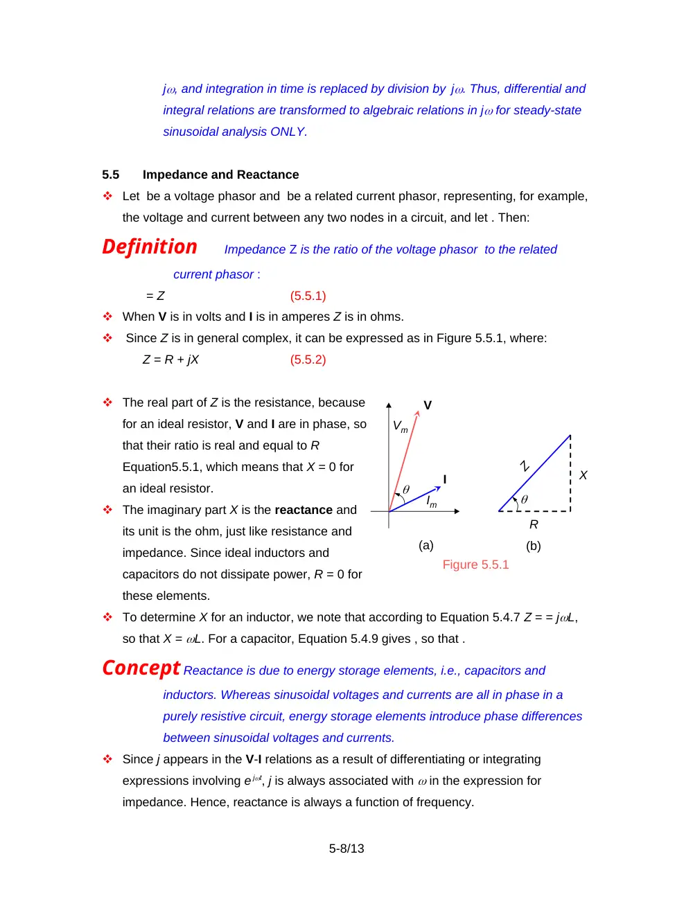
Since Z is in general complex, it can be expressed as in Figure 5.5.1, where:
Z = R + jX
(5.5.2)
The real part of Z is the resistance, because
for an ideal resistor, V and I are in phase, so
that their ratio is real and equal to R
Equation5.5.1, which means that X = 0 for
an ideal resistor.
The imaginary part X is the reactance and
its unit is the ohm, just like resistance and
impedance. Since ideal inductors and
capacitors do not dissipate power, R = 0 for
these elements.
To determine X for an inductor, we note that according to Equation 5.4.7 Z = = jL,
so that X = L. For a capacitor, Equation 5.4.9 gives , so that .
Concept Reactance is due to energy storage elements, i.e., capacitors and
inductors. Whereas sinusoidal voltages and currents are all in phase in a
purely resistive circuit, energy storage elements introduce phase differences
between sinusoidal voltages and currents.
Since j appears in the V-I relations as a result of differentiating or integrating
expressions involving e
jt, j is always associated with in the expression for
impedance. Hence, reactance is always a function of frequency.
5-8/13
V
Z
R
X
(a)
(b)
Figure 5.5.1
Im
Vm
I
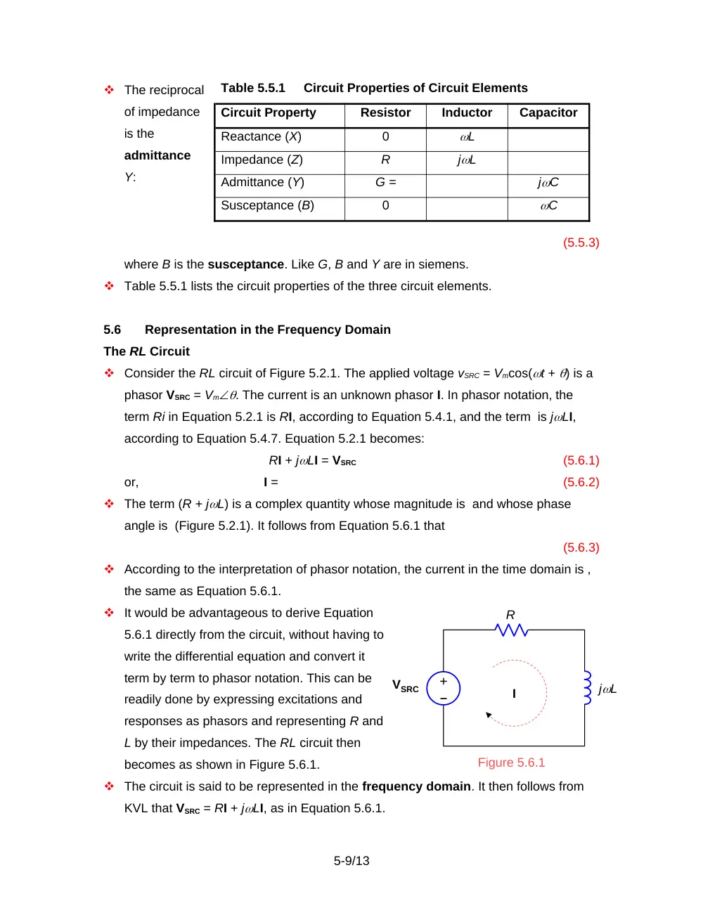
The reciprocal
of impedance
is the
admittance
Y:
(5.5.3)
where B is the susceptance. Like G, B and Y are in siemens.
Table 5.5.1 lists the circuit properties of the three circuit elements.
5.6
Representation in the Frequency Domain
The RL Circuit
Consider the RL circuit of Figure 5.2.1. The applied voltage vSRC = Vmcos(t + ) is a
phasor VSRC = Vm. The current is an unknown phasor I. In phasor notation, the
term Ri in Equation 5.2.1 is RI, according to Equation 5.4.1, and the term is jLI,
according to Equation 5.4.7. Equation 5.2.1 becomes:
RI + jLI = VSRC
(5.6.1)
or,
I =
(5.6.2)
The term (R + jL) is a complex quantity whose magnitude is and whose phase
angle is (Figure 5.2.1). It follows from Equation 5.6.1 that
(5.6.3)
According to the interpretation of phasor notation, the current in the time domain is ,
the same as Equation 5.6.1.
It would be advantageous to derive Equation
5.6.1 directly from the circuit, without having to
write the differential equation and convert it
term by term to phasor notation. This can be
readily done by expressing excitations and
responses as phasors and representing R and
L by their impedances. The RL circuit then
becomes as shown in Figure 5.6.1.
The circuit is said to be represented in the frequency domain. It then follows from
KVL that VSRC = RI + jLI, as in Equation 5.6.1.
5-9/13
Figure 5.6.1
+
jL
I
R
–
VSRC
Table 5.5.1
Circuit Properties of Circuit Elements
Circuit Property
Resistor
Inductor
Capacitor
Reactance (X)
0
L
Impedance (Z)
R
jL
Admittance (Y)
G =
jC
Susceptance (B)
0
C
Since KVL, KCL, and the v-i relations of circuit elements can all be expressed in the
frequency domain, it follows that:
Concept All circuit relations and theorems that apply to resistive circuits under dc
conditions apply for sinusoidal steady-state analysis in the frequency
domain to circuits that include resistance, inductance, and capacitance, with
voltages and currents represented as phasors and impedances of circuit
elements replacing resistance.
It should be emphasized that phasor analysis applies to the sinusoidal steady state
only.
Example 5.6.1
Voltage Division and Current Division
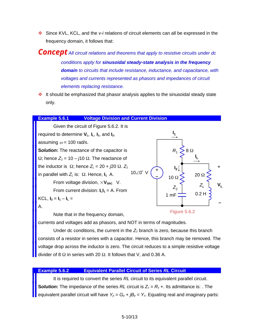
Given the circuit of Figure 5.6.2. It is
required to determine VL, IL, I1, and I2,
assuming = 100 rad/s.
Solution: The reactance of the capacitor is
; hence Z2 = 10 – j10 . The reactance of
the inductor is ; hence ZL = 20 + j20 . Z2
in parallel with ZL is: . Hence, I1 A.
From voltage division, VSRC V.
From current division: ILI1 = A. From
KCL, I2 = I1 – IL =
A.
Note that in the frequency domain,
currents and voltages add as phasors, and NOT in terms of magnitudes.
Under dc conditions, the current in the Z2 branch is zero, because this branch
consists of a resistor in series with a capacitor. Hence, this branch may be removed. The
voltage drop across the inductor is zero. The circuit reduces to a simple resistive voltage
divider of 8 in series with 20 . It follows that V, and 0.36 A.
Example 5.6.2
Equivalent Parallel Circuit of Series RL Circuit
It is required to convert the series RL circuit to its equivalent parallel circuit.
Solution: The impedance of the series RL circuit is Zs = Rs +. Its admittance is: . The
equivalent parallel circuit will have Yp = Gp + jBp = Ys. Equating real and imaginary parts:
5-10/13
I1
IL
+
VL
Figure 5.6.2
+
–
–
100 V
I2
8
10
20
1 mF
0.2 H
R1
Z2
ZL
,
and
(5.6.4)
Both Gp and Bp are frequency dependent. At = 0, Gp = and Bp = 0, as expected.
For an ideal inductor, Rs = 0 = Gp and Bp = –1/Ls, also as expected. Gp can also be
derived from the equality of power dissipation in Rs and Gp, since no power is dissipated
in Ls or Bp, and the two circuits are equivalent at their respective terminals. The power
dissipated in Rs is , whereas the power dissipated in Gp is . Equating these two quantities
gives the same value of Gp.
Example 5.6.3
Sinusoidal Steady State Using Node-Voltage Analysis
It is required to analyze the circuit of Figure 5.6.4 by the node-voltage method,
assuming = 1 rad/s. The circuit configuration is the same as that of Figure 3.3.2.
Solution: The admittance of the 20 H inductor is S,
whereas that of the capacitor is
j0.05 S. Following the usual
procedure for writing the node-
voltage equations, but using
admittances instead of
conductances, the node voltage
equation for node e is: j0.05Vb –
j0.05Vc – 0.1Vd +(0.1 – j0.05 +
j0.05 + 0.1)Ve = 0. Substituting Vb
= 10 gives:
-j0.05Vc – 0.1Vd + 0.2Ve = -j0.5
For node c: -0.2Vb + (0.2 + j0.05)Vc – j0.05Ve = -I, and for node d: 0.1Vd – 0.1Ve =
I + 0.1V. Adding these two equations to eliminate I and substituting Vb = 10 and V = Vc
– Ve, gives:
(0.1 + j0.05)Vc + 0.1Vd – j0.05Ve = 2
For the dependent voltage source, Vd – Vc = 2Vx = 2(Vb – Ve), or:
-Vc + Vd + 2Ve = 20
Solving these three equations using MATLAB gives: Vc = 6.7568 – j0.5405 V, Vd =
13.2432 + j0.5405 V, and Ve = Vc = 6.7568 – j0.5405 V.
Example 5.6.4
Sinusoidal Steady State Using Mesh-Current Analysis
It is required to
5-11/13
+
–
–
+
I2
I
Ix
V1
I3
V2
20
2 H
40
20
5 mF
+
_
100 V
a
0.1V
Vb
b
I
2Vx
+
+
Vx
V
c
d
Vc
Vd
Ve
– +
–
–
e
10
5
10
50 mF
Figure 5.6.4
20 H
analyze the circuit of Figure 5.6.7 by the mesh-current method, assuming = 10 rad/s.
The circuit configuration is the same as that of Figure 3.5.2.
Solution: The impedance of the 2 H inductor is j20 , that
of the 5 mF capacitor is , and that of the 2 mF capacitor is –j50 . The mesh-current
equation for mesh 1 is:
10I1 = -V1 – 4I, that for mesh 2 is: (60 + j20)I2 – 40I3 = V1. Adding and substituting I = I3:
10I1 + (60 + j20)I2 – 36I3 = 0
The mesh-current equation for mesh 3 is: (60 – j20)I3 – 40I2 = -V2, that for mesh 4
is: -j50I4 = V2 + 4I. Adding and substituting I = I3:
-40I2 + (56 – j20)I3 – j50I4 = 0
For the independent current source:
-I1 + I2 = 10
For the dependent current source: I4 – I3 = 2Ix, or:
-2I2 – I3 + I4 = 0
Solving using MATLAB, gives: I1 = -8.9443 + j0.2038 A, I2 = 1.0557 + j0.2038 A, I3
= -0.8383 + j0.9828 A, and I4 = 1.2730 + j1.3904 A.
5.7
Phasor Diagrams
Phasor diagrams showing various voltage and current phasors in a given circuit are
useful for illustrating the interrelations between the various variables involved,
particularly when some circuit variable is varied.
Example 5.7.1
Phase Shifter
Given the circuit of
Figure 5.7.1. It is required to
determine how the output
voltage vO changes as Rx is
varied from 0 to infinity,
assuming that no current is
drawn at the output.
Solution: The lattice
configuration of Figure 5.7.1 may be redrawn as a bridge configuration, for easier
visualization, and represented in the frequency domain as shown in Figure 5.7.2.
5-12/13
Rx
R
R
C
+
vO
vI = Vmcost
+
a
b
c
d
Figure 5.7.1
–
–
Since II, where , and the phasor I lags
the phasor I by 90, then point Q joining these
two phasors lies on the perimeter of a
semicircle of diameter Vm (Figure 5.7.3). If a
phasor I is drawn from point T at the tip of the
phasor , then VOI is the phasor from the origin
O to S at the tip of I.
When Rx = 0, VO = and . Q coincides
with O, and S coincides with T. As Rx
increases, Q moves clockwise
around the perimeter of its
semicircle. Likewise, S moves
clockwise around the
perimeter of a semicircle
because I is always parallel to
I and of the same magnitude.
As , I. Both plates of the
capacitor will be at the same
potential, and VO =. S would then lie at the tip of the phasor . At any Rx, VO = and .
It is seen from the geometry that, where . Substituting, gives: .
The circuit may be used to shift the phase of the output with respect to the input,
without altering the magnitude.
5-13/13
Rx
Rx
0
x
R
x
R
c
jX
O
S
Q
T
Rx I
I
Figure 5.7.3
VO
– RxI
Vm 0
Vm /20
– Vm /20
R
R
Rx
RxI
jXC
I
Vm/2
Vm/2
VO
+
+
+
0
m
V
a
b
d
c
–
–
–
–
+
+
–
Figure 5.7.2