
EECE 491 Lecture 2, Fall 2015
American University of Beirut · Discrete-time Signal Processing · 41 pages · Prof. Mohammad Mansour
Showing the first 10 of 41 pages. Download the PDF to see all of it.
More EECE 491 files
Show the text of this lab
Prof. M. Mansour
EECE 491: Discrete‐time Signal Processing
1
EECE 491: Discrete‐time Signal Processing
Mohammad M. Mansour
Dept. of Electrical and Compute Engineering
American University of Beirut
Lecture 2: Review of Signals, Systems, and Signal
Processing
Prof. M. Mansour
EECE 491: Discrete‐time Signal Processing
2
Announcements
Reading
– Chapter 1, Proakis
Prof. M. Mansour
EECE 491: Discrete‐time Signal Processing
3
Outline
Signals and signal types
– Continuous‐time vs. discrete‐time frequency
– Harmonically‐related complex exponentials
SP systems
Sampling
A/D and D/A
Quantization
– SQNR
Prof. M. Mansour
EECE 491: Discrete‐time Signal Processing
4
Signals
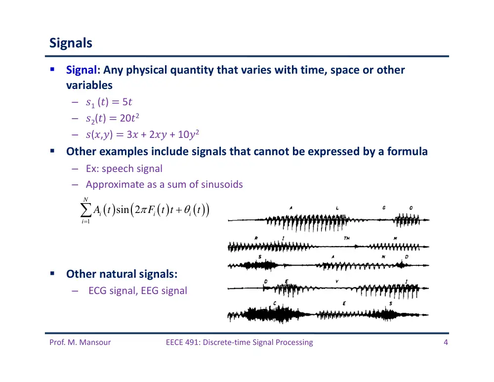
Signal: Any physical quantity that varies with time, space or other
variables
– �1 (�) � 5�
– �2(�) � 20�2
– �(�,�) � 3� + 2�� + 10�2
Other examples include signals that cannot be expressed by a formula
– Ex: speech signal
– Approximate as a sum of sinusoids
Other natural signals:
–
ECG signal, EEG signal
1
sin 2
N
i
i
i
i
A t
F t t
t
Prof. M. Mansour
EECE 491: Discrete‐time Signal Processing
5
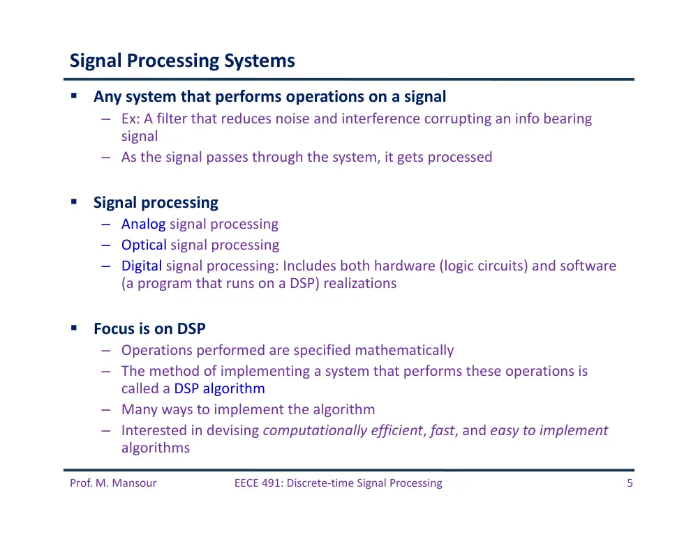
Signal Processing Systems
Any system that performs operations on a signal
– Ex: A filter that reduces noise and interference corrupting an info bearing
signal
– As the signal passes through the system, it gets processed
Signal processing
– Analog signal processing
– Optical signal processing
– Digital signal processing: Includes both hardware (logic circuits) and software
(a program that runs on a DSP) realizations
Focus is on DSP
– Operations performed are specified mathematically
– The method of implementing a system that performs these operations is
called a DSP algorithm
– Many ways to implement the algorithm
– Interested in devising computationally efficient, fast, and easy to implement
algorithms
Prof. M. Mansour
EECE 491: Discrete‐time Signal Processing
6
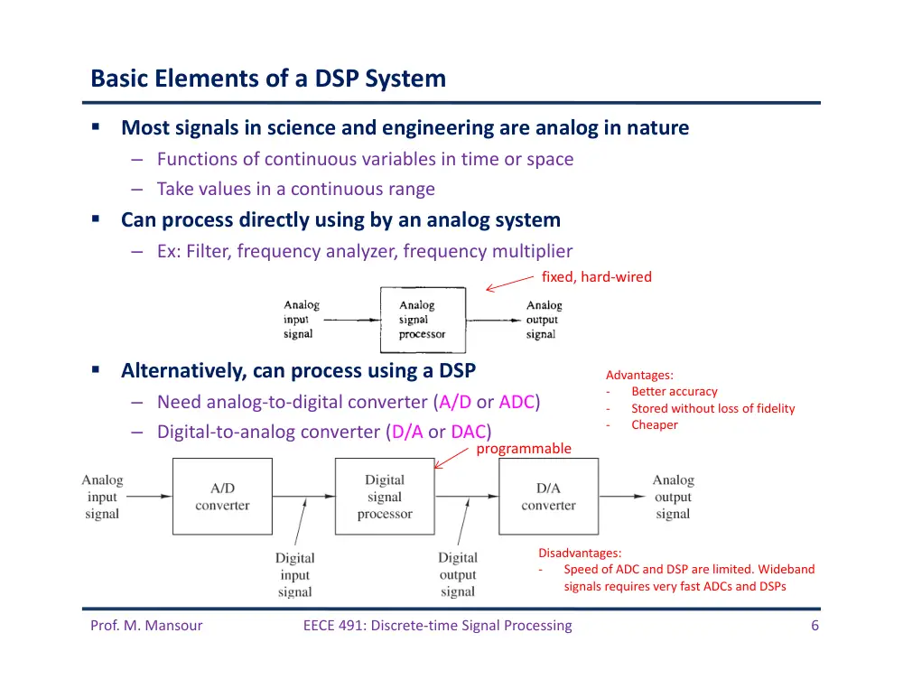
Basic Elements of a DSP System
Most signals in science and engineering are analog in nature
– Functions of continuous variables in time or space
– Take values in a continuous range
Can process directly using by an analog system
– Ex: Filter, frequency analyzer, frequency multiplier
Alternatively, can process using a DSP
– Need analog‐to‐digital converter (A/D or ADC)
– Digital‐to‐analog converter (D/A or DAC)
fixed, hard‐wired
programmable
Advantages:
‐
Better accuracy
‐
Stored without loss of fidelity
‐
Cheaper
Disadvantages:
‐
Speed of ADC and DSP are limited. Wideband
signals requires very fast ADCs and DSPs
Prof. M. Mansour
EECE 491: Discrete‐time Signal Processing
7
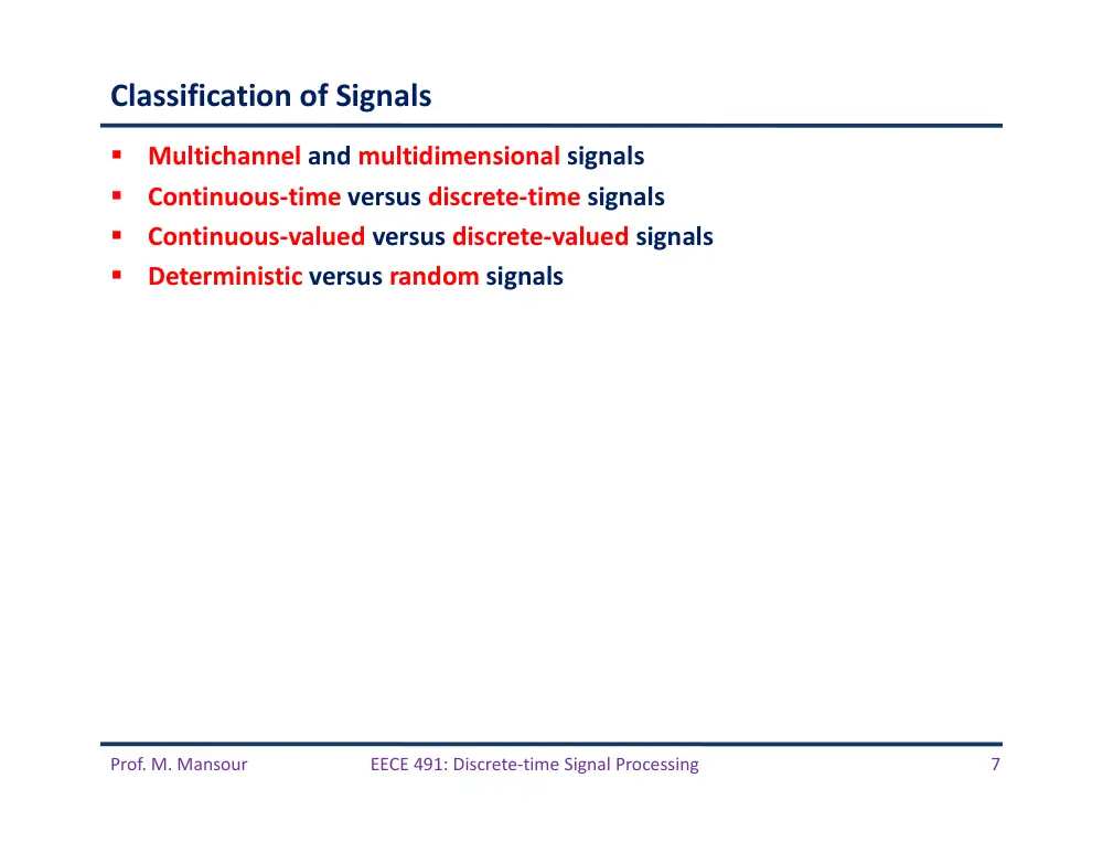
Classification of Signals
Multichannel and multidimensional signals
Continuous‐time versus discrete‐time signals
Continuous‐valued versus discrete‐valued signals
Deterministic versus random signals
Prof. M. Mansour
EECE 491: Discrete‐time Signal Processing
8
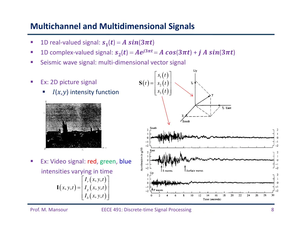
1D real‐valued signal: ��(�) � ���(���)
1D complex‐valued signal: ��(�) ������ � ���(���) + � � ���(���)
Seismic wave signal: multi‐dimensional vector signal
Ex: 2D picture signal
�(�,�) intensity function
Ex: Video signal: red, green, blue
intensities varying in time
Multichannel and Multidimensional Signals
1
2
3
s t
t
s
t
s
t
S
, ,
, ,
, ,
, ,
r
g
b
I
x y t
x y t
I
x y t
I
x y t
I
Prof. M. Mansour
EECE 491: Discrete‐time Signal Processing
9
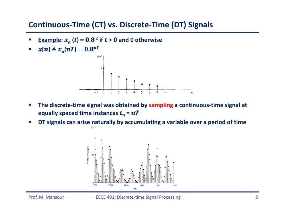
Continuous‐Time (CT) vs. Discrete‐Time (DT) Signals
Example: �� (�) �.� � if � > � and 0 otherwise
�[�] ≜ ��(��) �.���
The discrete‐time signal was obtained by sampling a continuous‐time signal at
equally spaced time instances �� = ��
DT signals can arise naturally by accumulating a variable over a period of time
Prof. M. Mansour
EECE 491: Discrete‐time Signal Processing
10
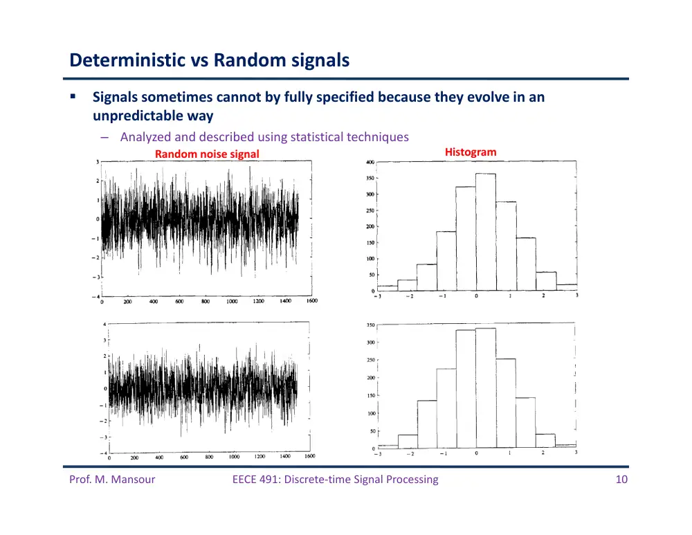
Deterministic vs Random signals
Signals sometimes cannot by fully specified because they evolve in an
unpredictable way
–
Analyzed and described using statistical techniques
Random noise signal
Histogram
Prof. M. Mansour
EECE 491: Discrete‐time Signal Processing
11
Continuous‐Valued vs Discrete‐Valued Signals
Values of a CT and DT signals can continuous or discrete
Discrete valued DT signals are called digital signals
Digital signals are obtained by quantizing a sampled CT signal
Prof. M. Mansour
EECE 491: Discrete‐time Signal Processing
12
Frequency of a CT Signal
�� (�) = ����(��+�), −∞ < � < ∞
–
A: Amplitude
–
�: Frequency in rad/sec; �=���, � is frequency in cycles/sec (Hz)
–
�: Phase in radians
Properties of analog sinusoidal signals
– For any fixed �, ��(�) is periodic with �� = 1/F
being its fundamental period
– CT sinusoidal signals with different frequencies
are themselves different
– Increasing F results in an increase in the rate of oscillation
These properties apply to class of complex‐exponential signals as well
– �� (�) = ���(��+�) = ����(��+�) + �����(��+�)
For mathematical convenience we use negative frequencies
– ���(��+�) = �/� ��(��+�) + �/� ��(��−�)
– Phasor representation
Prof. M. Mansour
EECE 491: Discrete‐time Signal Processing
13
Frequency of a DT Signal
–
A: Amplitude
–
�=���: Frequency in rad/sample; � is frequency in cycles/sample (Hz)
–
�: Phase in radians
1. Properties of DT sinusoidal signals: A DT sinusoid is periodic with period N if f is
rational.
–
Periodic: Smallest N that satisfies x[n+N] = x[n] for all n is called fundamental period
–
Ex: for a sinusoid with freq f0:
–
Ex:
–
Ex:
0
0
0
cos 2
cos 2
: 2
2
f
N
n
f n
k
f N
k
1
1
31/ 60
60
f
N
2
2
30 / 60
2
f
N
cos
,
a
x n
x
nT
n
n
Prof. M. Mansour
EECE 491: Discrete‐time Signal Processing
14
Properties of DT Sinusoidal Signals (cont’d)
2.
DT sinusoids whose frequencies are integer multiples of �� are identical
Hence, all sinusoidal sequences �� (�)= ����(���+�), � = 0,1,… are identical
when �� = ��+ 2�k, where −� ≤ �� ≤ �
Any sequence resulting from a sinusoid with freq |�| > � is identical to a
sequence obtained from a sinusoidal signal with|�| < �
Sinusoids with |�| > � are called aliases
Frequencies in the range −� ≤ � ≤ � or −1/2 ≤ � ≤ 1/2 are unique
–
Frequencies in the range |�| > � or |�| > 1/2 are aliases
Ex: for � ≤ �� ≤ 2�, consider two sinusoids with freqs ��=�� and �� = 2� −��
–
��[�] = ����(��� + �)
– ��[�] = ����(���+�) = ����((��−��)�+�) = �1[�]
0
0
cos
2
cos
n
n
Prof. M. Mansour
EECE 491: Discrete‐time Signal Processing
15
Properties of DT Sinusoidal Signals (cont’d)
3.
The highest rate of oscillation is attained when � =± � or � = ±1/2
Prof. M. Mansour
EECE 491: Discrete‐time Signal Processing
16
Harmonically‐Related Complex Exponentials (HRCEs)
Harmonically‐Related Complex Exponentials: Set of periodic complex
exponentials with fundamental frequencies multiple of a single frequency
CT exponentials:
– Fundamental period: 1/(��0) = ��/�
– Fundamental freq: ��0
– Periodic signals with period ��/� and hence also with period ��.
– F0 can take any value and all members of the set are distinct
Basic signals are a linear combination of HRCEs:
– ��: arbitrary complex constants
– ��(�) is periodic with fundamental period �� = 1/�0.
– Representation is called Fourier series expansion of ��(�) and��’s are Fourier
series coefficients.
– ��(�) is called the kth harmonic
0
0
2
,
0, 1, 2,
jk
t
j
kF t
ks
t
e
e
k
0
jk
t
a
k
k
k
k
k
x
t
c s
t
c e
Prof. M. Mansour
EECE 491: Discrete‐time Signal Processing
17
Discrete‐Time Exponentials
A DT complex exponential is periodic if its relative frequency is a rational
number, choose �0 = 1/�
Define the set of DT‐HRCEs as
Note that
Hence there are only N distinct DT‐HRCEs in the above set
All members have a common period of N samples
Choose any consecutive N complex exponentials to form the set of
HRCEs
– Most convenient choice:
Linear combination:
– Periodic with period N
– Called Fourier series expansion for a periodic DT signal, with Fourier
coefficients {��}
– ��[�] is called the kth harmonic
0
2
,
0, 1, 2,
j
kf n
ks
n
e
k
0
2
2
j
kf
n N
j
n
k N
k
k
s
n
e
e
s
n
s
n
2
/ ,
0,1,
,
1
j
kn N
ks
n
e
k
N
1
1
2
/
0
0
N
N
j
kn N
k
k
k
k
k
x n
c s
n
c e
Prof. M. Mansour
EECE 491: Discrete‐time Signal Processing
18
Example
Assume you have stored in memory of a DSP one cycle of the sinusoid:
–
�[�] = sin(���/�+�) where � = ���/�, where � and � are integers
–
i.e., the samples x[0], x[1], …, x[N‐1] are stored in the processor’s memory
Q1: Determine how this table of values can be used to obtain values of
harmonically related sinusoids having the same phase
–
That is find �2[�] = sin(���2/�+�), �3[�] = sin(���3/�+�), …, �k[�] = sin(���k/�+�)
Answer: Let ��[�]= ���(����/�+�) having frequency ��= �/� which is
harmonically related to x[n].
–
��[n] = ���(����/�+�) = �[�� mod N]
–
Read off values from memory for every n to determine all xk[n]
–
Ex: Assume N = 10, and k = 2. The 10 values of the harmonic sequence x2[n] are:
–
Ex: Assume N = 10, and k = 3. The 10 values of the harmonic sequence x3[n] are:
x2[0] = x[0]
x2[1] = x[2]
x2[2] = x[4]
x2[3] = x[6]
x2[4] = x[8]
x2[5] = x[0]
x2[6] = x[2]
x2[7] = x[4]
x2[8] = x[6]
x2[9] = x[8]
(two periods)
x3[0] = x[0]
x3[1] = x[3]
x3[2] = x[6]
x3[3] = x[9]
x3[4] = x[2]
x3[5] = x[5]
x3[6] = x[8]
x3[7] = x[1]
x3[8] = x[4]
x3[9] = x[7]
(one period)
Prof. M. Mansour
EECE 491: Discrete‐time Signal Processing
19
Example (cont’d)
Q2: Determine how this table of values can be used to obtain sinusoids having
the same frequency but different phase.
–
That is given
–
Determine
Answer:
– The same applies for any other phase
sin 2
/
,
2
/
kx
n
nk
N
q N
sin 2
/
,
2
/
ky
n
nk
N
N
sin 2
/
2
/
sin 2
/
2
/
sin 2
1
/
1
k
k
y
n
nk
N
k
N
nk
N
k
N
n
k
N
x
n
2
/
m N
Prof. M. Mansour
EECE 491: Discrete‐time Signal Processing
20
A/D and D/A Conversion
Prof. M. Mansour
EECE 491: Discrete‐time Signal Processing
21
A/D and D/A Conversion
Three steps:
– Sampling: Take samples of a CT signal at discrete time instances: �[�]=��(��),
T is the sampling period, and � = 1/� is the sampling rate.
• Uniform or periodic sampling
– Quantization: Convert a DT continuous‐valued signal into a digital signal.
• x�[�] = �(�[�]), where |�[�]−��[�]| is the quantization error
– Coding: Each discrete value ��[�] is mapped to a b‐bit binary number
Prof. M. Mansour
EECE 491: Discrete‐time Signal Processing
22
Sampling of Analog Signals
�[�] = ��(��), −∞ < � < ∞
Sampling rate: �� = 1/� (samples per sec, Hertz)
Relationship between t and n: � = �� = �/��
Hence there exists a relationship between frequency F (analog signal)
and f (DT signal)
Prof. M. Mansour
EECE 491: Discrete‐time Signal Processing
23
Sampling of Analog Signals (cont’d)
��(�) = ����(����+�), when sampled at ��= 1/� gives
CT: −∞ < � < ∞ −∞ < Ω < ∞
DT: −�/�<�<�/�
−�<�<�
Therefore:
Hence: The frequency of a CT sinusoid when sampled at a rate �� = 1/� must fall
in the range −��/� ≤ � ≤ ��/�
Map an infinite frequency range of a CT signal into a finite frequency range for
the DT signal
���� = ��/2
cos
,
a
x n
x
nT
n
n
cos 2
/
cos 2
1
2
2
2
a
s
s
s
s
x
nT
x n
A
nF F
A
nf
F
f
F
F
f
F
T
F
F
1
1
1
1
2
2
2
2
2
2
s
s
s
F
F
F
F
F
T
T
Prof. M. Mansour
EECE 491: Discrete‐time Signal Processing
24
Example
Consider two CT signals sampled at Fs = 40Hz
– �1(�) = ���2�(10)�
– �2(�) = ���2�(50)�
Corresponding DT signals are:
– �1(�) = ���2�(10/40)� = cos(�/2 �)
– �2(�) = ���2�(50/40)� = cos(5�/2 �) = cos(�/2 �)
– Therefore �1(�) = �2(�)
The two DT signals are identical and hence they are indistinguishable
We say that the frequency 50Hz is an alias of the frequency F1 = 10Hz at
the sampling rate of 40 samples/sec.
Also all frequencies �1 + 40�, � = 0, 1, 2, … are aliases as well
Prof. M. Mansour
EECE 491: Discrete‐time Signal Processing
25
Sampling of Analog Signals (cont’d)
Two cases:
Case I: If
, then f0 is in the range . The relationship
between F0 and f0 is one to one, and it is possible to reconstruct ��(�) from �[�].
Case II: Otherwise, for sinusoids with frequencies ��= �0
+���, � =±�, ±�,… If they are sampled at Fs, it is clear that Fk is outside the
fundamental range. Hence the sampled signal in this case is
sample @ ��= �/�
sample @�� = �/�
0
cos 2
ax
t
A
F t
0
0
0
cos 2
,
a
s
F
x
n
A
f n
f
F
0
2
2
s
s
F
F
F
0
1
1
2
2
f
cos 2
a
k
x
t
A
F t
cos 2
a
k
x
t
A
F t
0
0
0
cos 2
cos 2
cos 2
s
s
s
F
kF
x n
A
n
F
F
A
F n
A
f n
Prof. M. Mansour
EECE 491: Discrete‐time Signal Processing
26
Sampling of Analog Signals (cont’d)
�0 �
�
� Hz
�1 � �
�
� Hz
0
k
s
F
F
kF
1
0
7
1
8
F
F
Prof. M. Mansour
EECE 491: Discrete‐time Signal Processing
27
Example
Consider the analog signal ��(�) = ����(�����)
Q1: Determine the minimum sampling rate required to avoid aliasing.
A1: ��,��� = 2×� = 2×50 = 100��
Q2: Suppose ��(�) is sampled at ��= 200Hz. What is the resulting DT
signal?
A2:
Q3: Suppose ��(�) is sampled at �� = ��Hz. What is the resulting DT
signal?
A3:
Q4: What is the frequency 0 < � < ��/2 of an analog sinusoid that yields
samples identical to those in Q3?
A4: For the sampling rate ��= 75 Hz, we have � =��� = 75�. The
frequency of the DT signal in Q3 is � = 1/3. So the frequency of the CT
signal is � = 25 Hz and the corresponding sinusoid is ��(�) = ����(����)
3cos 100
3cos
200
2
n
n
x n
100
4
2
3cos
3cos
3cos
75
3
3
n
n
n
x n
Prof. M. Mansour
EECE 491: Discrete‐time Signal Processing
28
The Sampling Theorem
Need to know the maximum frequency content of a signal to sample it
properly
Example:
– Speech signal: N sinusoids, where Fmax = 3000 Hz
– TV signal: N sinusoids, where Fmax = 5 MHz
If signal is not band limited to Fmax, we need to low‐pass filter it before
sampling
To avoid ambiguities resulting from aliasing, must select
In this case, frequency Fi in the above sinusoid maps to
1
sin 2
N
a
i
i
i
i
x
t
A
F t t
t
max
2
sF
F
1
1
such that - 2
2
i
i
i
i
s
F
F
f
f
F
Prof. M. Mansour
EECE 491: Discrete‐time Signal Processing
29
The Sampling Theorem (cont’d)
Sampling Theorem: If the highest frequency in an analog signal ��(�) is
Fmax=� and the signal is sampled at ��> �����≡ ��, then ��(�) can be
exactly recovered from its samples xa[n] using the interpolation function
�(�), and ��(�) can be written as follows:
Interpolation function
Reconstruction formula
sin 2
2
Bt
g t
Bt
a
a
n
s
s
n
n
x
t
x
g t
F
F
Prof. M. Mansour
EECE 491: Discrete‐time Signal Processing
30
The Sampling Theorem (cont’d)
When the sampling is performed exactly at the minimum rate �� � ��,
then
Nyquist rate: �������� � ����� � ��
Process called Ideal D/A conversion
sin 2
/ 2
2
2
/ 2
a
a
n
B t
n
B
n
x
t
x
B
B t
n
B
Prof. M. Mansour
EECE 491: Discrete‐time Signal Processing
31
Sinc Function
zero crossings of
normalized sinc
occur at non‐zero
integers
Prof. M. Mansour
EECE 491: Discrete‐time Signal Processing
32
Example
Q1: What is the Nyquist rate?
A1: The frequencies of ��(�) are ��= � ���, ��= � ���, ��= � ���. Hence �� must be at
least �����= �� ��� which is the Nyquist rate.
Q2: Assume signal is sampled at Fs = 5000 samp/s. What is the DT signal obtained?
A2: Note here the choice of �� is less than the Nyquist rate. Hence aliasing will occur. The
maximum frequency that can be represented without aliasing is ��/� = �.� ���. This can
be shown as well as follows:
Q3:What is the analog signal ��(�) that we can reconstruct from the samples if we use ideal
interpolation?
A3: The freq components present in the signal are ��=��∙��=� ��� and ��= ��∙��= � ���,
the analog signal recovered is ��(�) = �� ��������� − � ���������
3cos2000
5sin6000
10cos12000
ax
t
t
t
t
3
6
3cos2
5sin2
10cos2
5
5
5
3
3cos2
5sin2
10cos2
5
5
5
2
13cos2
5sin2
5
5
a
a
s
n
x n
x
nT
x
F
n
n
n
n
n
n
n
n
1
2
1
2
5,
5
f
f
Prof. M. Mansour
EECE 491: Discrete‐time Signal Processing
33
Quantization
Prof. M. Mansour
EECE 491: Discrete‐time Signal Processing
34
Quantization of Continuous‐Amplitude Signals
Quantizer operation on the samples �[�]:
Quantization error:
Quantization
[ ]
qx
n
Q x n
q
q
e
n
x
n
x n
0.9
0
0
0
n
n
x n
n
Prof. M. Mansour
EECE 491: Discrete‐time Signal Processing
35
Quantization of Continuous‐Amplitude Signals (cont’d)
�(�) requires � significant digits in order to be represented in full
Prof. M. Mansour
EECE 491: Discrete‐time Signal Processing
36
Quantization of Continuous‐Amplitude Signals (cont’d)
Assume want to retain d significant digits
– Quantization by rounding: drop excess digits and round to nearest digit
– Quantization by truncation : drop excess digits
In previous example, retain only one significant digit
Quantization levels L: Number of allowed values of a digital signal
Quantization step
Quantization error for rounding is limited to the range
x[n]:
– ����: maximum value of �(�)
– ����: minimum value of �(�)
– Dynamic range: ����− ����
– Quantization step is determined by L and dynamic range:
For a fixed dynamic range, increasing � decreases .
Quantization is an irreversible process
– The map �(∙) is a many‐to‐one mapping since all samples within are assigned
the same quantization level
2
2
qe
n
max
min
1
x
x
L
Prof. M. Mansour
EECE 491: Discrete‐time Signal Processing
37
Quantization of Sinusoidal Signals
��(�) = � ������
– If �� satisfies Nyquist rate, then quantization is the only error in the A/D
process
Prof. M. Mansour
EECE 491: Discrete‐time Signal Processing
38
Quantization of Sinusoidal Signals (cont’d)
Thus we can evaluate quantization error by quantizing the analog signal ��(�)
instead of the DT signal �[�].
From figure, ��(�) is almost linear between quantization levels:
: time that ��(�) stays within the quantization levels
Approximate quantization error as:
Mean square error power ��:
If the quantizer uses b bits of accuracy and it covers the entire range 2A, the
quantization step is and hence
,
2
qe
t
t
t
2
2
2
2
2
0
1
1
2
2
2
12
q
q
P
e
t dt
t dt
2
2b
A
2
2
/ 3
2
q
b
P A
Prof. M. Mansour
EECE 491: Discrete‐time Signal Processing
39
Quantization of Sinusoidal Signals (cont’d)
Average power of the signal ��(�) = � ������:
Quality of an A/D converter is measured by the signal‐to‐quantization noise ratio (SQNR)
Expressed in decibels (dB):
SQNR increases by almost 6 dB for every bit added to the word length
Note: The assumption was that the input signal we a sinusoid and the range of the
quantizer spans the dynamic range of the signal. A similar result holds for every such
signal, not necessarily a sinusoid, as will be shown later in the course
Example: Most compact disc players use a sampling frequency of 44.1 kHz and 16‐bit
sample resolution, which implies an SQNR of 96 dB.
2
2
0
0
0
0
1
2
cos
,
2
2
p
T
x
p
p
A
P
A
t
dt
F
T
T
3 22
2
b
x
q
P
SQNR
P
10log10
1.76
6.02
SQNRdB
SQNR
b
Prof. M. Mansour
EECE 491: Discrete‐time Signal Processing
40
Coding of Quantized Bits
Coding process assigns a unique binary number to each quant. Level
For L levels, we need L different binary numbers
With a word length of b bits we can create 2b levels
– Hence � ≥ log2�
Commercially available A/D converters may be obtained with a finite
precision of 16 bits or less
Generally, the higher the sampling speed and the finer the quantization,
the more expensive the device becomes
Prof. M. Mansour
EECE 491: Discrete‐time Signal Processing
41
D/A Conversion
Ideally, we should use the “sinc” interpolation function
– Too complicated for practical purposes
– Use sub‐optimum interpolation techniques
Can use zero‐order hold: Hold constant the value of 1 sample until the next
one
Linear interpolation: Connect successive samples with straight line segments
– Other higher order techniques
Generally, sub‐optimum interpolations result in passing frequencies above
Fs/2
These undesirable frequencies must be removed by passing the output of
the interpolator through a proper analog filter, called a post‐filter or
smoothing filter.