
EECE 491 Lecture 6, Spring 2016
American University of Beirut · Discrete-time Signal Processing · 34 pages


Showing the first 10 of 34 pages. Download the PDF to see all of it.
More EECE 491 files
Show the text of this lab
Prof. M. Mansour
EECE 491: Discrete‐time Signal Processing
1
EECE 491: Discrete‐time Signal Processing
Mohammad M. Mansour
Dept. of Electrical and Compute Engineering
American University of Beirut
Lecture 6: Digital Filters
Part I: Frequency Selective Filters
Prof. M. Mansour
EECE 491: Discrete‐time Signal Processing
2
Announcements
Reading
–
Chapter 5, Proakis
Prof. M. Mansour
EECE 491: Discrete‐time Signal Processing
3
Outline
Ideal Filter Characteristics
Lowpass Filters (LPF)
Highpass Filters (HPF)
Bandpass Filters (BPF)
Digital Resonators
Notch Filters
Comb Filters
All‐Pass Filters
Inverse Systems
Minimum Phase Systems
Prof. M. Mansour
EECE 491: Discrete‐time Signal Processing
4
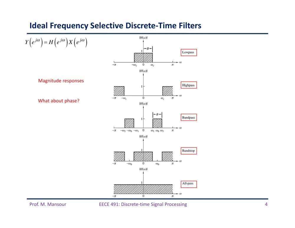
Ideal Frequency Selective Discrete‐Time Filters
Magnitude responses
What about phase?
j
j
j
Y e
H e
X e
Prof. M. Mansour
EECE 491: Discrete‐time Signal Processing
5
Phase Response of Ideal Filters
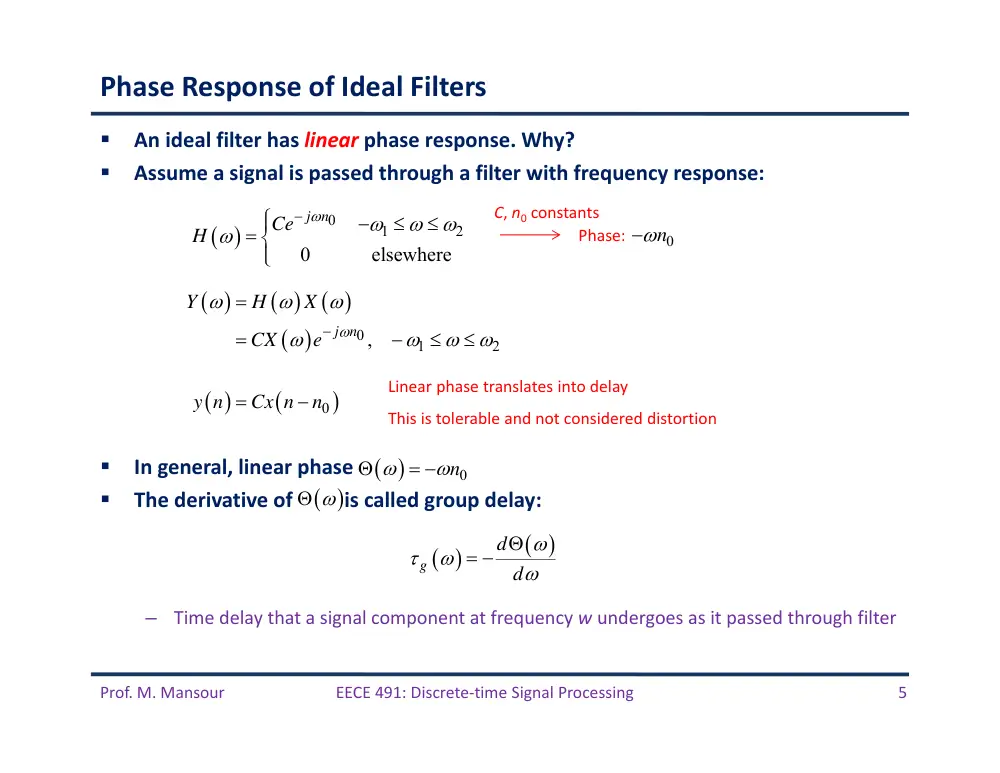
An ideal filter has linear phase response. Why?
Assume a signal is passed through a filter with frequency response:
In general, linear phase
The derivative of is called group delay:
–
Time delay that a signal component at frequency w undergoes as it passed through filter
0
1
2
0
elsewhere
Ce j n
H
C, n0 constants
0
1
2
j n ,
Y
H
X
CX
e
0
y n
Cx n
n
Linear phase translates into delay
This is tolerable and not considered distortion
Phase:
g
d
d
n0
n0
Prof. M. Mansour
EECE 491: Discrete‐time Signal Processing
6
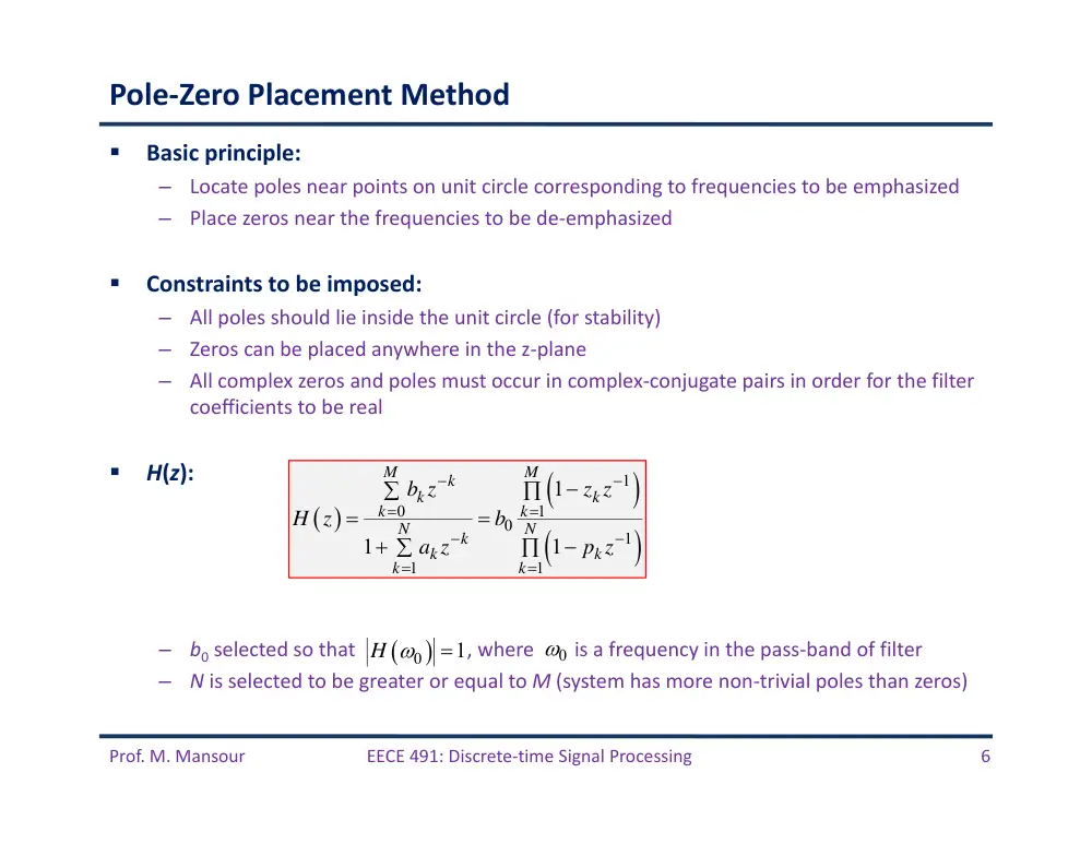
Pole‐Zero Placement Method
Basic principle:
–
Locate poles near points on unit circle corresponding to frequencies to be emphasized
–
Place zeros near the frequencies to be de‐emphasized
Constraints to be imposed:
–
All poles should lie inside the unit circle (for stability)
–
Zeros can be placed anywhere in the z‐plane
–
All complex zeros and poles must occur in complex‐conjugate pairs in order for the filter
coefficients to be real
H(z):
–
b0 selected so that
, where
is a frequency in the pass‐band of filter
–
N is selected to be greater or equal to M (system has more non‐trivial poles than zeros)
1
0
1
0
1
1
1
1
1
1
M
M
k
k
k
k
k
N
N
k
k
k
k
k
z z
b z
H z
b
a z
p z
0
1
H
0
Prof. M. Mansour
EECE 491: Discrete‐time Signal Processing
7
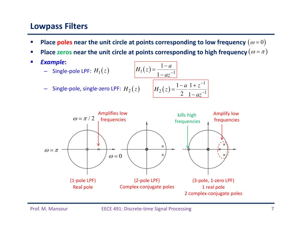
Lowpass Filters
Place poles near the unit circle at points corresponding to low frequency
Place zeros near the unit circle at points corresponding to high frequency
Example:
–
Single‐pole LPF:
–
Single‐pole, single‐zero LPF:
1
1
1
1
a
H
z
az
1
2
1
1
1
2 1
a
z
H
z
az
(2‐pole LPF)
Complex‐conjugate poles
(1‐pole LPF)
Real pole
(3‐pole, 1‐zero LPF)
1 real pole
2 complex‐conjugate poles
Amplifies low
frequencies
kills high
frequencies
Amplify low
frequencies
0
H1
z
H2
z
/ 2
0
Prof. M. Mansour
EECE 491: Discrete‐time Signal Processing
8
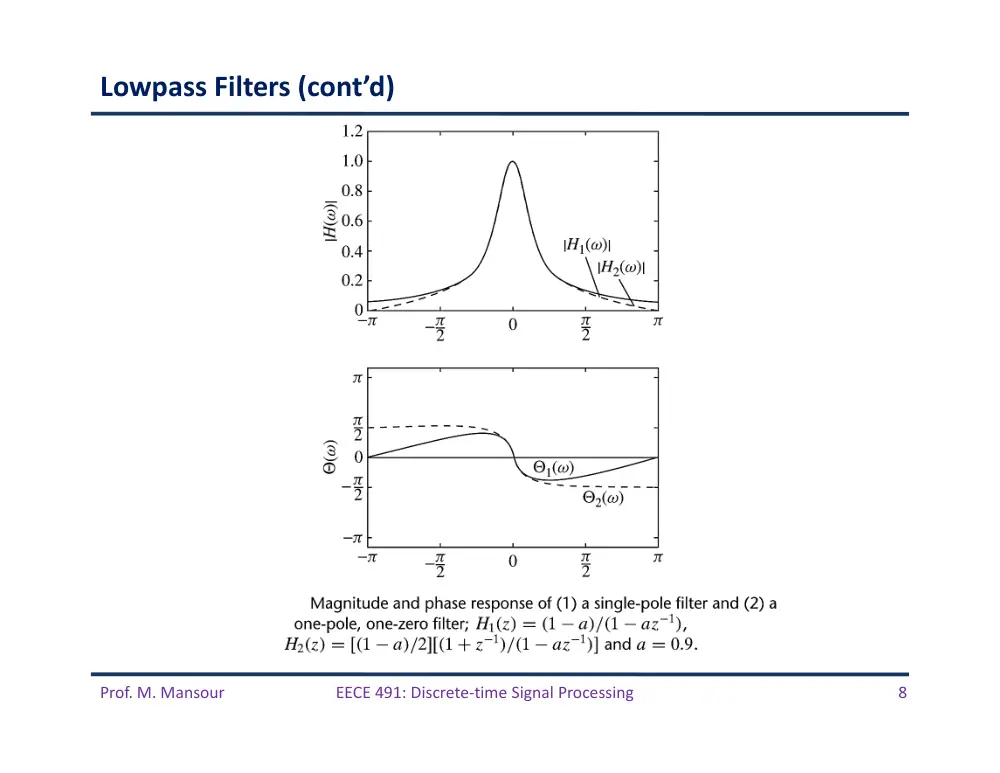
Lowpass Filters (cont’d)
Prof. M. Mansour
EECE 491: Discrete‐time Signal Processing
9
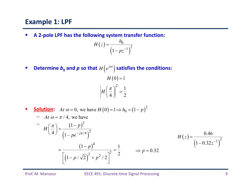
Example 1: LPF
A 2‐pole LPF has the following system transfer function:
Determine b0 and p so that
satisfies the conditions:
Solution:
–
.
–
0
1 2
1
b
H z
pz
2
0
1
1
4
2
H
H
0.32
p
1 2
0.46
1
0.32
H z
z
j
H e
2
0
0, we have
0
1
1
At
H
b
p
/ 4, we have
At
2
2
/4
4
2
2
2
1
4
1
1
1
2
1
/
2
/ 2
j
p
H
pe
p
p
p
Prof. M. Mansour
EECE 491: Discrete‐time Signal Processing
10
Highpass Filters
Pole‐zero placement
Simply reflect the pole‐zero locations of the low‐pass filters about the imaginary
axis
Same ideas can be extended to design bandpass filters
1
3
1
1
1
2 1
a
z
H
z
az
Prof. M. Mansour
EECE 491: Discrete‐time Signal Processing
11
Highpass Filters (cont’d)
Prof. M. Mansour
EECE 491: Discrete‐time Signal Processing
12
Example 2: BPF
Design a 2‐pole bandpass filter that has the center of its bandpass at , zero in its
frequency response characteristic at and , and a magnitude of at
Solution: The filter must have:
–
Poles at
–
Zeros at
Hence, system function looks like:
Gain factor G is chosen such that H has unit gain at center frequency:
Parameter r determined from
:
BPF
2
2
2
1
1
1
z
z
H
z
G z
jr
z
jr
G z
z
r
2
2
2
1
1
2
2
1
r
H
G
G
r
2 2
2
2
4
2
1
2
2cos 8
/ 9
4
1
0.7
9
2
4
1
2
cos 8
/ 9
r
H
r
r
r
2
BPF
2
0.15 1
1
0.7
z
H
z
z
/ 2
0
1/
2
4
/ 9
/2
1,2
j
p
re
jr
1
1 and 2
1
z
z
at
4
/ 9
H
Prof. M. Mansour
EECE 491: Discrete‐time Signal Processing
13
Example 2: BPF (cont’d)
Prof. M. Mansour
EECE 491: Discrete‐time Signal Processing
14
A Lowpass to Highpass Filter Transformation
Given a Lowpass filter with frequency response
A Highpass filter can be obtained by translating by radians:
In time domain, this corresponds to multiplication by
–
Change the signs of the odd‐numbered samples of
LPF:
HPF:
HP
LP
j
j
H
e
H
e
HP
LP
LP
1
n
n
j
h
n
e
h
n
h
n
1
0
N
M
k
k
k
k
y n
a y n
k
b x n
k
0
LP
1
1
M
j k
k
j
k
N
j k
k
k
b e
H
e
a e
0
HP
1
1
1
1
M
k
j k
k
j
k
N
k
j k
k
k
b e
H
e
a e
1
0
1
1
N
M
k
k
k
k
k
k
y n
a y n
k
b x n
k
hLP
n
j
HLP
e
j
HLP
e
j n
e
hLP
n
Prof. M. Mansour
EECE 491: Discrete‐time Signal Processing
15
Digital Resonators
A Special 2‐pole bandpass filter with the pair of complex‐conjugate poles located
near the unit circle
Resonator: Filter “resonates” in the vicinity of the pole location
Applications: Bandpass filtering and speech recognition
Prof. M. Mansour
EECE 491: Discrete‐time Signal Processing
16
Digital Resonators
For a resonant peak frequency at or near
:
–
Select the complex conjugate poles to be
We can select up to two zeros:
–
Choice 1 H1(z): select both zeros to be at origin
–
Choice 2 H2(z): select zeros to be at z = +1 and z = –1. This choice eliminates frequencies
� � 0 and � � � which is useful in many applications
For choice 1, we have
Gain at �0 is 1:
0
1
1
1
0
0
0
1
0
0
0
0
0
0
2 0
1
1
1
1
1
1
j
j
j
j
j
j
j
b
H
z
re
z
re
z
b
H
re
e
re
e
b
r
re
0
1
0
2
0
2
0
0
1
1
1
2 cos2
1
1
2 cos2
b
H
r
r
r
b
r
r
r
0
0
1,2
,
0
1
j
p
re
r
0
Prof. M. Mansour
EECE 491: Discrete‐time Signal Processing
17
Digital Resonators
At frequency �, we have
2
0
1
0
0
1
1
2 cos2
1
1
j
j
j
j
r
r
r
H
re
e
re
e
2
0
1
1
2
1
1
2 cos2
r
r
r
H
U
U
1
2
2
��
x
x
�
���
�
�� (�)
�� (�)
2
1
0
2
2
0
1
2 cos
1
2 cos
U
r
r
U
r
r
1
2
U
U
reaches its minimum at frequency
2
1
0
1
cos
cos
2
r
r
r
(resonant frequency)
As r → 1, �� → �0
Prof. M. Mansour
EECE 491: Discrete‐time Signal Processing
18
Digital Resonators
As � approaches 1, the resonant peak becomes sharper
A quantitative measure is the 3dB bandwidth ∆�:
–
For � close to 1, ∆� ≈ 2(1−�)
Prof. M. Mansour
EECE 491: Discrete‐time Signal Processing
19
Digital Resonators (cont’d)
Choice 2: select zeros to be at � = +1 and � = −1
1
1
2
1
1
0
0
2
2
0
0
1
1
1
1
1
1
1
j
j
j
j
j
z
z
H
z
G
re
z
re
z
e
H
G
re
re
Prof. M. Mansour
EECE 491: Discrete‐time Signal Processing
20
Notch Filters
Contains perfect nulls in its frequency response characteristic
–
Used in applications where specific frequencies must be eliminated (e.g. power‐line 60
Hz and its harmonics in instrumentation systems)
FIR systems
–
To create a null at frequency ��, we introduce a pair of complex‐conjugate zeros on the
unit circle at an angle ��
1
1
0
0
0
1
2
0
0
1
1
1
2cos
j
j
H z
b
e
z
e
z
b
z
z
Nulls at �� and ��
Prof. M. Mansour
EECE 491: Discrete‐time Signal Processing
21
Notch Filters
Nearby frequencies
attenuated
Prof. M. Mansour
EECE 491: Discrete‐time Signal Processing
22
Notch Filters
Disadvantages of FIR notch filters
–
Frequencies components around the desired nulls are severely attenuated (i.e., the
notch has a relatively large bandwidth)
Solution: Use IIR approach and introduce poles to amplify nearby frequencies
Place a pair of complex‐conjugate poles at
–
Effect: They introduce a resonance in the vicinity of the null and thus reduce the
bandwidth of the notch (note the poles are not on the unit circle: 0 < � < 1)
System function:
0
1,2
j
p
re
1
2
0
0
1
2
2
0
1
2cos
1
2 cos
z
z
H z
b
r
z
r z
Prof. M. Mansour
EECE 491: Discrete‐time Signal Processing
23
Notch Filters
Prof. M. Mansour
EECE 491: Discrete‐time Signal Processing
24
Comb Filters
A notch filter in which the nulls occur periodically across the frequency band
Example: Moving average FIR
Has � zeros on the unit circle at:
2
/
1 ,
1,2,
,
j
k
M
k
M
z
e
1
1
1
1
1
1
M
z
H z
M
z
/2
1
sin
2
1
sin
/ 2
j M
j
M
e
H e
M
0
1
1
M
k
y n
x n
k
M
� = ��
Prof. M. Mansour
EECE 491: Discrete‐time Signal Processing
25
Comb Filters
In general, a comb filter can be created by taking an FIR filter with
and replacing � by ��
��(ej�) is an �‐order repetition of �(ej�) in the range � ≤ � ≤ �
If �(�) has a spectral null at some frequency ��, then ��(�) has periodically
spaced nulls at �� = ��+ ���/� for �=�,�,…,�−�
0
M
k
k
H z
h k z
0
M
kL
L
k
H
z
h k z
0
M
j
jkL
L
k
jL
H
e
h k e
H e
Prof. M. Mansour
EECE 491: Discrete‐time Signal Processing
26
Comb Filters
Prof. M. Mansour
EECE 491: Discrete‐time Signal Processing
27
Comb Filters
Prof. M. Mansour
EECE 491: Discrete‐time Signal Processing
28
Comb Filters
Back to moving average FIR
Has zeros at
–
For all integer values of � except � = 0, �, 2�, …
1
1
1
1
1
1
M
z
H z
M
z
� → ��
1
1
1
1
1
L M
L
L
z
H
z
M
z
/2
1
sin
1
2
1
sin
/ 2
j LM
L
L M
H
e
M
L
2
/
1
j
k L M
z
e
Prof. M. Mansour
EECE 491: Discrete‐time Signal Processing
29
All‐Pass Filters
Has constant response for all frequencies, but phase varies
Used to alter phase characteristics of a system, e.g., equalization
Simplest all pass system is delay system
Another system:
Since
–
Then the system is all‐pass system
If �� is a pole of �(�) then �/�� is a zero of �(�). Poles and zeros are reciprocals
of one another
1,
0
j
H e
k
H z
z
2
1
1
z e j
H
H z H z
Prof. M. Mansour
EECE 491: Discrete‐time Signal Processing
30
All‐Pass Filters
Prof. M. Mansour
EECE 491: Discrete‐time Signal Processing
31
All‐Pass Filters
General form of all‐pass filters (real coefficients)
1
1
*
1
ap
1
1
*
1
1
1
1
1
1
N
N
C
R
k
k
k
k
k
k
k
k
z
z
z
H
z
z
z
z
Prof. M. Mansour
EECE 491: Discrete‐time Signal Processing
32
Inverse Systems
*
*
*
1
I
I
I
w n
h
n
h n
x n
x n
h
n
h n
n
H z H
z
Prof. M. Mansour
EECE 491: Discrete‐time Signal Processing
33
Minimum‐Phase Systems
Invertibility of an LTI system is related to the characteristics of the phase spectral
function of the system
Example:
In frequency domain:
1
1
1
1
1
2
1
1
1
2
2
1
1
1
2
2
H
z
z
z
z
H
z
z
z
z
1
2
5
cos
4
H
H
1
sin
arctan 1
cos
2
2
sin
arctan 2
cos
Net phase change is 0
Minimum phase system
Net phase change is
Maximum phase system
Has zero inside unit circle
Has zero outside unit circle
Prof. M. Mansour
EECE 491: Discrete‐time Signal Processing
34
Minimum‐Phase Systems
A minimum‐phase FIR system of length M + 1:
If all zeros are inside the unit circle, then each factor contributes a zero phase
change, hence the overall system is minimum phase
–
Since group delay is derivative of phase, a minimum phase system has least delay
If all zeros are outside unit circle, then system is maximum phase
Otherwise it is called mixed‐phase system
Minimum‐phase IIR systems (stable and causal):
–
All poles and zeros are inside unit circle
Minimum phase property ensures that a stable system that is minimum phase
has stable inverse which is also minimum phase