
EECE 491 Lecture 8, Spring 2016
American University of Beirut · Discrete-time Signal Processing · 46 pages
Showing the first 10 of 46 pages. Download the PDF to see all of it.
More EECE 491 files
Show the text of this lab
Prof. M. Mansour
EECE 491: Discrete‐time Signal Processing
1
EECE 491: Discrete‐time Signal Processing
Mohammad M. Mansour
Dept. of Electrical and Compute Engineering
American University of Beirut
Lecture 8: Digital Filters
Part III: IIR Filter Design
Prof. M. Mansour
EECE 491: Discrete‐time Signal Processing
2
Announcements
Reading
–
O&S
• Chapter 7
• Appendix B
Prof. M. Mansour
EECE 491: Discrete‐time Signal Processing
3
Outline
Continuous‐Time Filters
Techniques for IIR Filter Design
–
Design by Impulse Invariance
–
Design by Bilinear Transformation
Prof. M. Mansour
EECE 491: Discrete‐time Signal Processing
4
Continuous‐Time Filters
Prof. M. Mansour
EECE 491: Discrete‐time Signal Processing
5
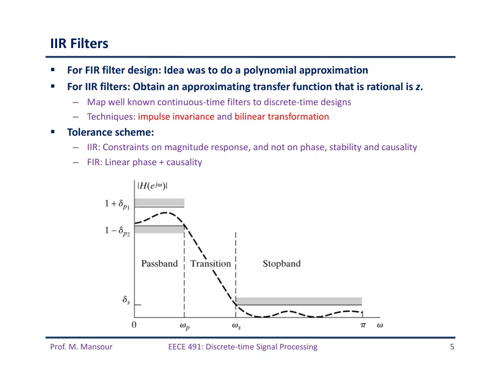
IIR Filters
For FIR filter design: Idea was to do a polynomial approximation
For IIR filters: Obtain an approximating transfer function that is rational is z.
–
Map well known continuous‐time filters to discrete‐time designs
–
Techniques: impulse invariance and bilinear transformation
Tolerance scheme:
–
IIR: Constraints on magnitude response, and not on phase, stability and causality
–
FIR: Linear phase + causality
Prof. M. Mansour
EECE 491: Discrete‐time Signal Processing
6
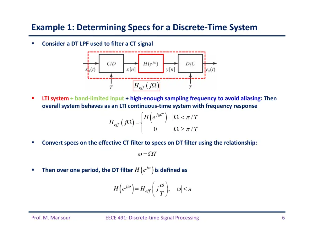
Example 1: Determining Specs for a Discrete‐Time System
Consider a DT LPF used to filter a CT signal
LTI system + band‐limited input + high‐enough sampling frequency to avoid aliasing: Then
overall system behaves as an LTI continuous‐time system with frequency response
Convert specs on the effective CT filter to specs on DT filter using the relationship:
Then over one period, the DT filter is defined as
/
0
/
j T
eff
H e
T
H
j
T
T
j
H e
,
j
eff
H e
H
j T
Heff
j
Prof. M. Mansour
EECE 491: Discrete‐time Signal Processing
7
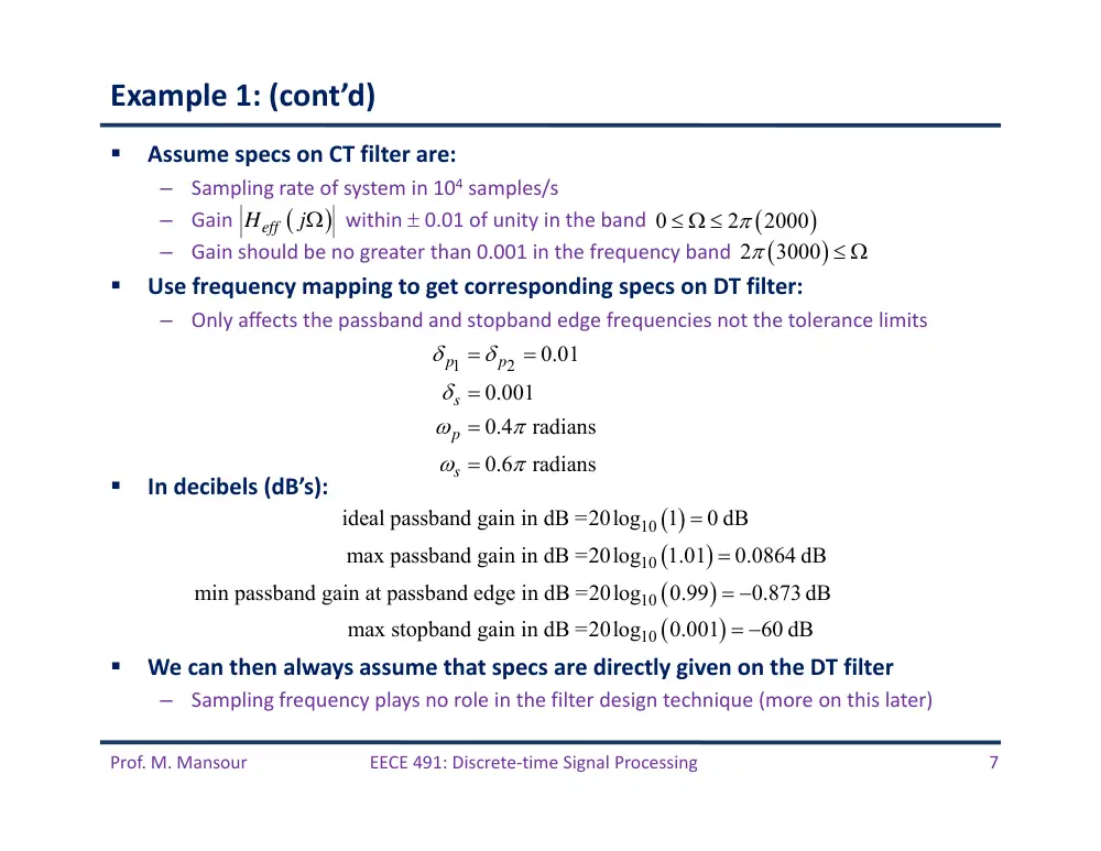
Example 1: (cont’d)
Assume specs on CT filter are:
–
Sampling rate of system in 104 samples/s
–
Gain
within 0.01 of unity in the band
–
Gain should be no greater than 0.001 in the frequency band
Use frequency mapping to get corresponding specs on DT filter:
–
Only affects the passband and stopband edge frequencies not the tolerance limits
In decibels (dB’s):
We can then always assume that specs are directly given on the DT filter
–
Sampling frequency plays no role in the filter design technique (more on this later)
Heff
j
0
2
2000
2
3000
1
2
0.01
0.001
0.4
radians
0.6
radians
p
p
s
p
s
10
10
10
10
ideal passband gain in dB =20log
1
0 dB
max passband gain in dB =20log
1.01
0.0864 dB
min passband gain at passband edge in dB =20log
0.99
0.873 dB
max stopband gain in dB =20log
0.001
60 dB
Prof. M. Mansour
EECE 491: Discrete‐time Signal Processing
8
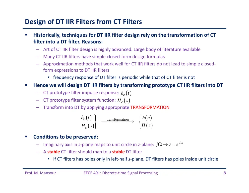
Design of DT IIR Filters from CT Filters
Historically, techniques for DT IIR filter design rely on the transformation of CT
filter into a DT filter. Reasons:
–
Art of CT IIR filter design is highly advanced. Large body of literature available
–
Many CT IIR filters have simple closed‐form design formulas
–
Approximation methods that work well for CT IIR filters do not lead to simple closed‐
form expressions to DT IIR filters
• frequency response of DT filter is periodic while that of CT filter is not
Hence we will design DT IIR filters by transforming prototype CT IIR filters into DT
–
CT prototype filter impulse response:
–
CT prototype filter system function:
–
Transform into DT by applying appropriate TRANSFORMATION
Conditions to be preserved:
–
Imaginary axis in s‐plane maps to unit circle in z‐plane:
–
A stable CT filter should map to a stable DT filter
• If CT filters has poles only in left‐half s‐plane, DT filters has poles inside unit circle
ch
t
Hc
s
transformation
c
c
h
t
h n
H z
H
s
j
j
z
e
Prof. M. Mansour
EECE 491: Discrete‐time Signal Processing
9
Review of Continuous‐Time Filters
Well‐known classes of CT filters:
–
Butterworth filter
–
Chebyshev filter
–
Elliptic filter
Prof. M. Mansour
EECE 491: Discrete‐time Signal Processing
10
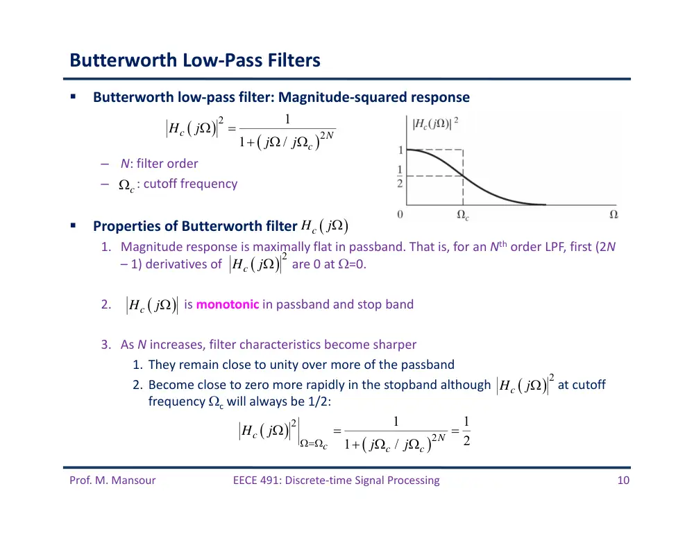
Butterworth Low‐Pass Filters
Butterworth low‐pass filter: Magnitude‐squared response
–
N: filter order
–
: cutoff frequency
Properties of Butterworth filter
1. Magnitude response is maximally flat in passband. That is, for an Nth order LPF, first (2N
– 1) derivatives of are 0 at =0.
2.
is monotonic in passband and stop band
3. As N increases, filter characteristics become sharper
1. They remain close to unity over more of the passband
2. Become close to zero more rapidly in the stopband although at cutoff
frequency c will always be 1/2:
Hc
j
Hc
j
2
Hc
j
2
2
1
1
/
c
N
c
H
j
j
j
c
2
Hc
j
2
2
1
1
2
1
/
c
N
c
c
c
H
j
j
j
Prof. M. Mansour
EECE 491: Discrete‐time Signal Processing
11
Butterworth Low‐Pass Filters (cont’d)
Prof. M. Mansour
EECE 491: Discrete‐time Signal Processing
12
Butterworth Low‐Pass Filters (cont’d)
Poles of
(roots of denominator) located on a circle of radius c at
equally spaced points:
–
2N poles equally spaced in angle on circle with radius c in s‐place, symmetrically
located wrt imaginary axis
–
No pole falls on imaginary axis
–
N even: no pole falls on real axis
–
N odd: one pole falls on real axis
–
Angular spacing between poles is /N.
2
2
2
2
1
1
1
/
1
/
c
c
c
s
j
N
N
c
c
H
s H
s
H
j
s
j
s
2
2
1
/
2
1
,
0,1,
,
1
N
j
k
N
c
s
e
k
N
N = 3
�� � �� ��
2
1
/
/2
,
0,1,
,
1
j
k
N
j
k
c
s
e
e
k
N
(and their symmetric points wrt imag axis)
Prof. M. Mansour
EECE 491: Discrete‐time Signal Processing
13
Butterworth Low‐Pass Filters (cont’d)
To determine to associate with a LPF from
–
Factorize into
–
Poles of will always occur in pairs: pole at
–
Need to choose only one pole from each pair
–
To obtain a stable and causal filter, choose all poles in left‐half part of s‐plane
Example: for N = 3
–
Choose poles at
–
Get
–
In general set numerator of to so that
Hc
s
2
Hc
j
2
Hc
j
c
c
H
s H
s
Hc s Hc s
s sk pole at s sk
sk c,
ce j2 /3,
ce j2 /3
x
x
x
Hc s
c
3
sc
sce j2 /3
s ce j2 /3
Hc s
c
3
Hc 0 1
Prof. M. Mansour
EECE 491: Discrete‐time Signal Processing
14
Chebyshev Filters
In Butterworth filter: Magnitude response in monotonic in both passband and
stopband
–
If filter specs are in terms on max passband and stopband approximation error, these
specs are exceeded toward the low‐frequency end of passband and above the stopband
cutoff frequency
More efficient approach leading to lower order filters
–
Distribute accuracy of approximation uniformly over passband or stopband or both
–
Achieved by choosing an approximation that has an equiripple behavior rather than a
monotonic behavior
Class of Chebyshev filters achieve equiripple behavior
–
Type I Chebyshev filters: Equiripple in passband, monotonic in stopband
–
Type II Chebyshev filters: Monotonic in passband, equiripple in stopband
Prof. M. Mansour
EECE 491: Discrete‐time Signal Processing
15
Type I Chebyshev Filters
First few values:
Chebyshev polynomials are orthogonal and satisfy the recurrence:
For , varies between 0 and 1
For x > 1, cos‐1(x) is imaginary and VN(x) behaves as a hyperbolic cosine, and
hence increases monotonically
2
2
2
1
1
/
c
N
c
H
j
V
1
cos
cos
VN
x
N
x
Type I Chebyshev Filter
0
1
1
1
2
2
1
cos cos
cos 2cos
2
1
V
x
V
x
x
x
V
x
x
x
1
1
2
N
N
N
V
x
xV
x
V
x
(Nth‐order Chebyshev polynomial)
0
1
x
2
VN
x
Prof. M. Mansour
EECE 491: Discrete‐time Signal Processing
16
Type I Chebyshev Filters (cont’d)
For 0 /c 1: ripples between 1 and 1/(1 + 2)
For /c > 1: decreases monotonically
Parameters to be specified: , c, N.
–
: specified by allowable passband ripple
–
c: specified by desired passband cutoff frequency
–
Order N: chosen so that stopband specs are met.
Poles of Chebyshev filter:
–
Lie on an ellipse in s‐plane
–
Ellipse defined by 2 circles
• Diameters = major & minor axes of ellipse
2
2
2
1
1
/
c
N
c
H
j
V
2
Hc
j
2
Hc
j
1/
1/
1/
1/
1
2
1
length of minor axis : 2
,
2
1
length of major axis : 2
,
2
1
N
N
c
N
N
c
a
a
b
b
Prof. M. Mansour
EECE 491: Discrete‐time Signal Processing
17
Type I Chebyshev Filters (cont’d)
To locate poles of Chebyshev filter
–
Identify points on major and minor circles equally spaced in angle with spacing /N.
–
Points are symmetrically located wrt imaginary axis
–
Point never falls on imaginary axis
–
A point occur on real axis for N odd, but not for N even.
–
Poles of filter then lie on ellipse
• Ordinate specified by points identified on major circle
• Abscissa specified by points identified on minor circle
Prof. M. Mansour
EECE 491: Discrete‐time Signal Processing
18
Type II Chebyshev Filters
Obtained from Type I Chebyshev filter via a transformation
–
Replace
–
To obtain
First design Type I filter, then apply transformation
2
2
2
2
1
/
/
N
c
N
c
V
V
2
1
2
2
1
1
/
c
N
c
H
j
V
Prof. M. Mansour
EECE 491: Discrete‐time Signal Processing
19
Elliptic Filters
Distribute error uniformly across both bandpass and stopband
–
Get equiripple both in passband and stopband
–
Best that can be achieved for a given filter order N.
• That is, for given values of 1, 2, and p, the transition band s ‐ p is smallest
Elliptic filters have the form:
–
To obtain equiripple in both bands, elliptic filters must have both zeros and poles
2
2
2
1
1
c
N
H
j
U
:
Jacobian Elliptic Function
UN
Filter has zeros on j‐axis in s‐plane
Prof. M. Mansour
EECE 491: Discrete‐time Signal Processing
20
Analog Filters in MATLAB
bilinear
Bilinear transformation method for analog-to-digital filter conversion
besselap
Bessel analog lowpass filter prototype
besself
Bessel analog filter design
buttap
Butterworth filter prototype
butter
Butterworth filter design
cheb1ap
Chebyshev Type I analog lowpass filter prototype
cheb2ap
Chebyshev Type II analog lowpass filter prototype
cheby1
Chebyshev Type I filter design (passband ripple)
cheby2
Chebyshev Type II filter design (stopband ripple)
ellip
Elliptic filter design
ellipap
Elliptic analog lowpass filter prototype
freqs
Frequency response of analog filters
lp2bp
Transform lowpass analog filters to bandpass
lp2bs
Transform lowpass analog filters to bandstop
lp2hp
Transform lowpass analog filters to highpass
lp2lp
Change cutoff frequency for lowpass analog filter
Prof. M. Mansour
EECE 491: Discrete‐time Signal Processing
21
Techniques for IIR Filter Design
Design by Bilinear Transformation
Prof. M. Mansour
EECE 491: Discrete‐time Signal Processing
22
Filter Design by Impulse Invariance
DT system h[n] is defined by “sampling” the impulse response of a CT system hc(t)
–
DT impulse response corresponds to samples of the CT filter to be designed or simulated
–
DT system: h[n], H(z), H(ej)
–
CT system: hc(t), Hc(s), Hc(j)
In “impulse invariance” design, h[n] is chosen such that
–
Td: represents the sampling interval (does not play a role in the design procedure)
–
This transformation preserves the impulse response of the system at the sampled points
Relationship of CT and DT frequency responses H(ej) and Hc(j)
–
Sampling a CT signal leads to periodic replication in frequency domain
–
If CT filter is band‐limited, so that
–
Then
d c
d
h n
T h
nT
2
j
c
k
d
d
H e
H
j
j
k
T
T
0,
/
c
d
H
j
T
, for
j
c
Td
H e
H
j
Prof. M. Mansour
EECE 491: Discrete‐time Signal Processing
23
Filter Design by Impulse Invariance (cont’d)
1
s
c
s
k
H
j
H
j
k
T
2
s
d
T
Hc
j
Hs
j
Band‐limited
2
0,
/
N
s
N
s
N
d
c
d
T
H
j
T
,
j
c
Td
H e
H
j
Prof. M. Mansour
EECE 491: Discrete‐time Signal Processing
24
Filter Design by Impulse Invariance (cont’d)
–
Related by a linear scaling of the frequency axis:
If CT filter is not band‐limited, then interference occurs, causing aliasing
If CT filter approaches zero at high frequencies, aliasing can then be negligible
When impulse‐invariance design procedure is used to utilize to CT filters to
design DT filters with certain specs
–
Need to transform these specs to CT domain through the frequency relationship
–
Design the CT filter with these specs and then transform back to DT domain to get H(ej)
–
Sampling period in this case can’t be used to control aliasing. Need to over‐design the CT
filter instead (to exceed the specs)
,
j
c
d
H e
H
j T
Td ,
CT filter is band-limited
0,
/
c
d
H
j
T
/
Td
Prof. M. Mansour
EECE 491: Discrete‐time Signal Processing
25
Filter Design by Impulse Invariance (cont’d)
Impulse invariance was defined as a relation in time domain
What is the corresponding relation between the system functions Hc(s) and H(z)?
Assume a causal continuous‐time filer expressed in terms of partial fractions:
–
Corresponding impulse response (inverse Laplace):
–
Impulse response of causal DT filter is obtained by sampling
–
Therefore:
d c
d
h n
T h
nT
1
N
k
c
k
k
A
H
s
s
s
1
0
0
0
N
s t
k
k
k
c
A e
t
h
t
t
d c
T h
t
1
1
N
s nT
k
d
d c
d
d
k
k
N
n
s T
k d
d
k
k
h n
T h
nT
T A e
u n
T A
e
u n
1
1 1
N
d
k
s T
k d
k
T A
H z
e
z
Prof. M. Mansour
EECE 491: Discrete‐time Signal Processing
26
Filter Design by Impulse Invariance (cont’d)
Pole at in s‐plane maps to a pole in z‐plane
If real part of sk is negative so that CT filter is stable, then
–
Corresponding pole in z‐plane lies inside unit circle, and hence DT filter is stable
Zeros are not mapped in the same way
Hence, under impulse invariance mapping, the s‐plane is not similarly mapped to
the z‐plane
1
1
1 1
N
N
k
d
k
c
s T
k d
k
k
k
A
T A
H
s
H z
s
s
e
z
k
s
s
s T
k d
k
z
z
e
1
s T
e k d
Prof. M. Mansour
EECE 491: Discrete‐time Signal Processing
27
Example: Impulse Invariance with a Butterworth Filter
Design a DT LPF by applying impulse invariance to a CT Butterworth filter
DT filter specs:
–
Passband gain between 0 dB and ‐1 dB
–
Stopband attenuation at least ‐15 dB
Note in the impulse invariance procedure, Td cancels out, so set it to 1
–
Therefore the frequency mapping simply becomes =
CT Butterworth filter specs
Magnitude of Butterworth filter is monotonic, then above constraints are
satisfied if
Butterworth filter: Determine N and c:
0.89125
1,
for 0
0.2
0.17783,
for 0.3
j
j
H e
H e
0.89125 Hc j
1,
for 0 0.2
Hc j
0.17783,
for 0.3
0
1
and
0.2
0.89125
0.3
0.17783
c
c
c
H
j
H
j
H
j
2
2
1
1
/
c
N
c
H
j
j
j
2
2
2
2
0.2
1
1
0.89125
0.3
1
1
0..17783
N
c
N
c
Prof. M. Mansour
EECE 491: Discrete‐time Signal Processing
28
Example: Impulse Invariance with a Butterworth Filter
Get solution:
–
N = 5.8858
–
c = 0.70474
Set N = 6
–
Substitute back and get c = 0.7032
Magnitude square has 2N = 12 poles
–
Need to choose 6 in left half s‐plane
–
Pair 1 (s1, s1*): ‐0.182 j 0.679
–
Pair 2 (s2, s2*): ‐0.497 j 0.497
–
Pair 3 (s3, s3*): ‐0.679 j 0.182
Obtain H(z) by replacing poles at sk in s‐plane with poles at
6
*
*
*
1
1
2
2
3
3
2
2
2
0.12093
0.3640
0.4945
0.9945
0.4945
1.3585
0.4945
c
Hc
s
s
s
s
s
s
s
s
s
s
s
s
s
s
s
s
s
s
sk
k
z
z
e
6th‐order Butterworth filter
Prof. M. Mansour
EECE 491: Discrete‐time Signal Processing
29
Example: Impulse Invariance with a Butterworth Filter
1
1
2
1
1
2
1
1
2
0.2871
0.4466
1 1.2686
0.7051
2.1428 1.1455
1 1.0691
0.3699
1.8557
0.6303
1
0.9972
0.2570
z
H z
z
z
z
z
z
z
z
z
Prof. M. Mansour
EECE 491: Discrete‐time Signal Processing
30
Extensions of Impulse Invariance
In impulse invariance design, h[n] is chosen as
–
This transformation preserves the impulse response of the system
Can use other invariance criteria to do the transformation
–
Example: “Step‐invariance”
–
Assume CT filter has a step response of sc(t). Then the step‐response of the DT system
s[n] is defined such that the “step response” remains invariant, i.e. s[n] = sc(nTd)
• Obtain step response of CT system (sc(t) and its Laplace transform Sc(s))
• Sample sc(t) to obtain s[n]
• Use the relationship between step response and impulse response to find h[n].
This way, if CT filter has good step response characteristics such as small rise time
and low peak overshoot, they will be preserved in the DT filter
Concept can be extended to “waveform invariance”
d c
d
h n
T h
nT
1
1
s n
h n
u n
H z
S z
z
Prof. M. Mansour
EECE 491: Discrete‐time Signal Processing
31
Techniques for IIR Filter Design
Design by Bilinear Transformation
Prof. M. Mansour
EECE 491: Discrete‐time Signal Processing
32
Bilinear Transformation
Algebraic relationship between s and z variables that maps entire j‐axis in s‐
plane into one revolution of unit circle in z‐plane
–
Map is not linear since
–
This map is used only when this warping of frequency axis is acceptable
Consider Hc(s) and H(z):
–
Bilinear map: replace s by
–
Td is included for historical reasons. Difference equation of H(z) can be obtained by
applying trapezoidal integration rule to the differential equation corresponding to Hc(s)
with Td as step size
Solving for z:
Substituting s = + j:
1
1
2
1
1
d
z
s
T
z
1
1
2
1
1
c
d
z
H z
H
T
z
1
/ 2
1
/ 2
d
d
T
s
z
T
s
1
/ 2
/ 2
1
/ 2
/ 2
d
d
d
d
T
j T
z
T
j T
Prof. M. Mansour
EECE 491: Discrete‐time Signal Processing
33
Bilinear Transformation
If < 0 then |z| < 1 for any , and if > 0 then |z| > 1 for any
–
Pole in left‐half s‐plane maps inside unit circle in z‐plane
–
Therefore, a causal and stable CT filter maps to a causal and stable DT filter
To show that entire j‐axis in s‐plane maps unit circle in z‐plane, let = 0, then
–
Hence |z| = 1 for any . Then falls on unit circle and takes the form
1
/ 2
/ 2
1
/ 2
/ 2
d
d
d
d
T
j T
z
T
j T
1
/ 2
1
/ 2
d
d
j T
z
j T
1
/ 2
1
/ 2
j
d
d
j T
e
j T
Prof. M. Mansour
EECE 491: Discrete‐time Signal Processing
34
Bilinear Transformation
Prof. M. Mansour
EECE 491: Discrete‐time Signal Processing
35
Bilinear Transformation: Relationship Between and
1
1
2
1
2
1
,
1
1
j
j
j
d
d
z
e
s
z
e
s
T
T
z
e
/2
/2
2
sin
/ 2
2
2 tan
/ 2
2
cos
/ 2
j
j
d
d
e
j
j
s
j
j
T
T
e
2
0
tan
/ 2
or
2arctan
d / 2
d
T
T
Prof. M. Mansour
EECE 491: Discrete‐time Signal Processing
36
Frequency Warping of Bilinear Transformation
•
Frequency warping inherent in the
bilinear transformation of a
continuous‐time lowpass filter into a
discrete‐time lowpass filter.
•
To achieve the desired discrete‐time
cutoff frequencies, the continuous‐
time cutoff frequencies must be pre‐
warped as indicated.
•
Bilinear transformation is useful
when this non‐linearity is tolerable as
in the case of filters that approximate
ideal piecewise‐constant magnitude
response characteristics
Prof. M. Mansour
EECE 491: Discrete‐time Signal Processing
37
Distortion of Phase Response
Apply bilinear transformation to linear phase factor
–
Get DT phase angle of
linear phase
phase resulting from
bilinear transformation
e s
2
/
tan
/ 2
Td
Prof. M. Mansour
EECE 491: Discrete‐time Signal Processing
38
Example: Bilinear Transformation of a Butterworth Filter
Design a DT LPF by applying bilinear transformation to a CT Butterworth filter
DT filter specs:
–
Passband gain between 0 dB and ‐1 dB
–
Stopband attenuation at least ‐15 dB
CT Butterworth filter specs (choose Td = 1)
Magnitude of Butterworth filter is monotonic, then above constraints are
satisfied if
Butterworth filter: Determine N and c:
0.89125
1,
for 0
0.2
0.17783,
for 0.3
j
j
H e
H e
0.89125
1,
for 0
2tan 0.2
/ 2
0.17783,
for 2tan 0.3
/ 2
c
c
H
j
H
j
0
1
and
2tan 0.1
0.89125
2tan 0.15
0.17783
c
c
c
H
j
H
H
j
2
2
1
1
/
c
N
c
H
j
j
j
2
2
2
2
2tan 0.1
1
1
0.89125
2tan 0.15
1
1
0.17783
N
c
N
c
2 tan
/ 2
2tan
/ 2
Td
•
Get N = 5.305
•
Round to N = 6
•
Substitute to get c=0.766
Prof. M. Mansour
EECE 491: Discrete‐time Signal Processing
39
Example: Bilinear Transformation of a Butterworth Filter
In s‐plane, there are 12 poles
–
Choose 6 pole‐pairs in left‐half s‐plane
–
Apply bilinear transformation with Td = 1 to get H(z):
2
2
2
0.20238
0.3996
0.5871
1.0836
0.5871
1.4802
0.5871
Hc
s
s
s
s
s
s
1
1
2 1
1
z
s
z
6
1
1
2
1
2
1
2
0.0007378 1
1 1.2686
0.7051
1 1.0106
0.3583
1
0.9044
0.2155
z
H z
z
z
z
z
z
z
Prof. M. Mansour
EECE 491: Discrete‐time Signal Processing
40
Example: Bilinear Transformation of a Butterworth Filter
Prof. M. Mansour
EECE 491: Discrete‐time Signal Processing
41
Design Comparisons
Design a DT filter by applying Bilinear transformation to Butterworth, Chebyshev
Type I and II, and Elliptic filters
DT filter specs: Meet or exceed the following
passband edge frequency
0.5
radians
stopband edge frequency
0.6
radians
max passband gain
0 dB
min passband gain
0.3 dB
max stopband gain
30 dB
p
s
10
1
1
10
1
2
10
20log
1
0 dB
0
20log
1
0.3 dB
0.0339
20log
30 dB
0.0316
p
p
p
p
s
s
Prof. M. Mansour
EECE 491: Discrete‐time Signal Processing
42
Butterworth Filter: 15th‐Order
Prof. M. Mansour
EECE 491: Discrete‐time Signal Processing
43
Chebyshev Type I Filter: 7th‐order
Prof. M. Mansour
EECE 491: Discrete‐time Signal Processing
44
Chebyshev Type II Filter: 7th‐order
Prof. M. Mansour
EECE 491: Discrete‐time Signal Processing
45
Elliptic Filter: 5th‐order, Exceeds Design Specifications
Prof. M. Mansour
EECE 491: Discrete‐time Signal Processing
46
Elliptic Filter: 5th‐order, Exceeds Design Specifications