
EECE 491 Lecture 9, Spring 2016
American University of Beirut · Discrete-time Signal Processing · 39 pages
Showing the first 10 of 39 pages. Download the PDF to see all of it.
More EECE 491 files
Show the text of this lab
Prof.
M.
Mansour
EECE
491:
Discrete-‐time
Signal
Processing
1
EECE
491:
Discrete-‐time
Signal
Processing
Mohammad
M.
Mansour
Dept.
of
Electrical
and
Compute
Engineering
American
University
of
Beirut
Lecture
9:
Sampling
of
Continuous-‐Time
Signals
Prof.
M.
Mansour
EECE
491:
Discrete-‐time
Signal
Processing
2
Announcements
§
Reading
–
O&S
• Chapter
4
Prof.
M.
Mansour
EECE
491:
Discrete-‐time
Signal
Processing
3
Outline
1. Periodic
Sampling
2. Frequency
Domain
Representation
of
Sampling
3. Reconstruction
of
a
Band-‐limited
Signal
from
its
Samples
4. D.T. Processing
of
C.T. Signals
5. C.T. Processing
of
D.T. Signals
Prof.
M.
Mansour
EECE
491:
Discrete-‐time
Signal
Processing
4
Notation
§
Continuous-‐time
signal:
§
Discrete-‐time
signal:
§
Continuous-‐time
Fourier
transform:
§
Discrete-‐time
Fourier
transform:
§
Continuous-‐time
frequency:
§
Discrete-‐time
frequency:
§
D.T.
:
Discrete-‐Time
§
C.T.
:
Continuous-‐Time
§
F.T.
:
Fourier
Transform
cx ( )
t
[ ]
x n
(
)
Xc
jΩ
(
)
j
X e ω
Ω
ω
Prof.
M.
Mansour
EECE
491:
Discrete-‐time
Signal
Processing
5
Periodic
Sampling
Prof.
M.
Mansour
EECE
491:
Discrete-‐time
Signal
Processing
6
Periodic
(Uniform)
Sampling
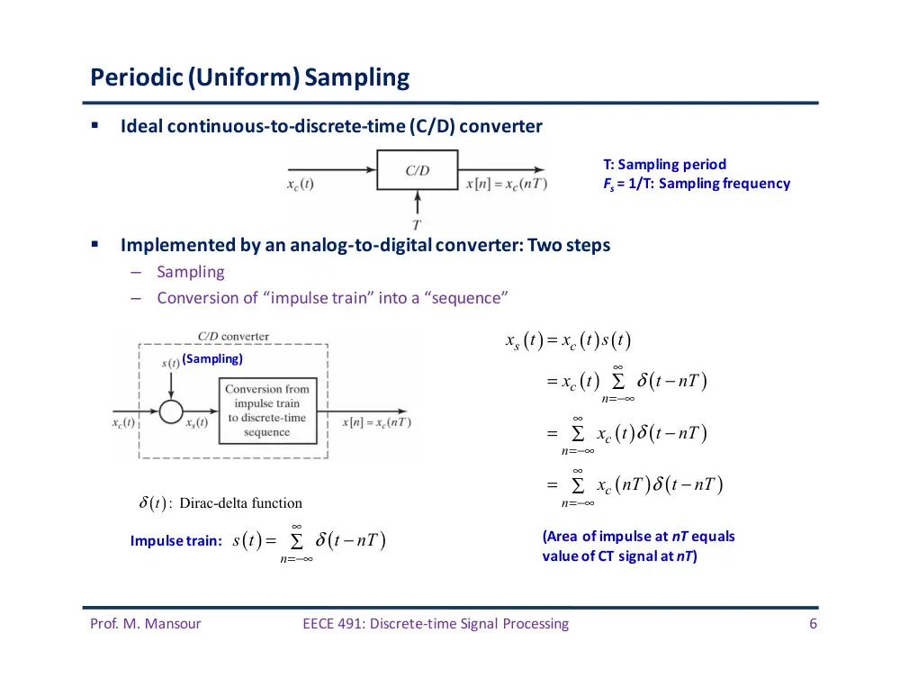
§
Ideal
continuous-‐to-‐discrete-‐time
(C/D)
converter
§
Implemented
by
an
analog-‐to-‐digital
converter:
Two
steps
–
Sampling
–
Conversion
of
“impulse
train”
into
a
“sequence”
( )
(
)
n
s t
t
nT
δ
∞
=−∞
=
−
∑
T:
Sampling
period
Fs =
1/T:
Sampling
frequency
Impulse
train:
�
( )
( ) ( )
( )
(
)
( ) (
)
(
) (
)
s
c
c
n
c
n
c
n
x
t
x
t s t
x
t
t
nT
x
t
t
nT
x
nT
t
nT
δ
δ
δ
∞
=−∞
∞
=−∞
∞
=−∞
=
=
−
∑
=
−
∑
=
−
∑
(Sampling)
( ): Dirac-delta function
t
δ
(Area
of
impulse
at
nT equals
value
of
CT
signal
at
nT)
Prof.
M.
Mansour
EECE
491:
Discrete-‐time
Signal
Processing
7
Periodic
Sampling
Prof.
M.
Mansour
EECE
491:
Discrete-‐time
Signal
Processing
8
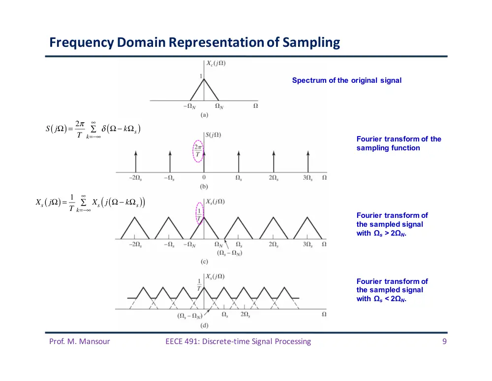
Frequency
Domain
Representation
of
Sampling
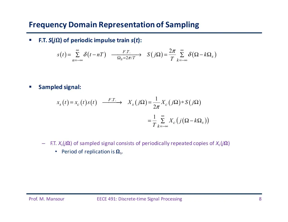
§
F.T.
S(j𝛀)
of
periodic
impulse
train
s(t):
§
Sampled
signal:
–
F.T.
Xs(j𝛀)
of
sampled
signal
consists
of
periodically
repeated
copies
of
Xc(j𝛀)
• Period
of
replication
is
𝛀s.
( )
(
)
(
)
(
)
. .
2 /
2
F T
s
T
s
n
k
s t
t
nT
S j
k
T
π
π
δ
δ
∞
∞
Ω =
=−∞
=−∞
=
−
⎯⎯⎯⎯→
Ω =
Ω − Ω
∑
∑
( )
( ) ( )
(
)
(
)
(
)
. .
1
2
F T
s
c
s
c
x
t
x
t s t
X
j
X
j
S j
π
=
⎯⎯⎯→
Ω =
Ω ∗
Ω
(
)
(
)
1
c
s
k
X
j
k
T
∞
=−∞
=
Ω − Ω
∑
Prof.
M.
Mansour
EECE
491:
Discrete-‐time
Signal
Processing
9
Frequency
Domain
Representation
of
Sampling
Spectrum of the original signal
Fourier transform of the
sampling function
Fourier transform of
the sampled signal
with Ωs > 2ΩN.
Fourier transform of
the sampled signal
with Ωs < 2ΩN.
S jΩ
(
) = 2π
T
δ Ω − kΩs
(
)
k=−∞
∞
∑
Xs jΩ
(
) = 1
T
Xs j Ω − kΩs
(
)
(
)
k=−∞
∞
∑
Prof.
M.
Mansour
EECE
491:
Discrete-‐time
Signal
Processing
10
Frequency
Domain
Representation
of
Sampling
§
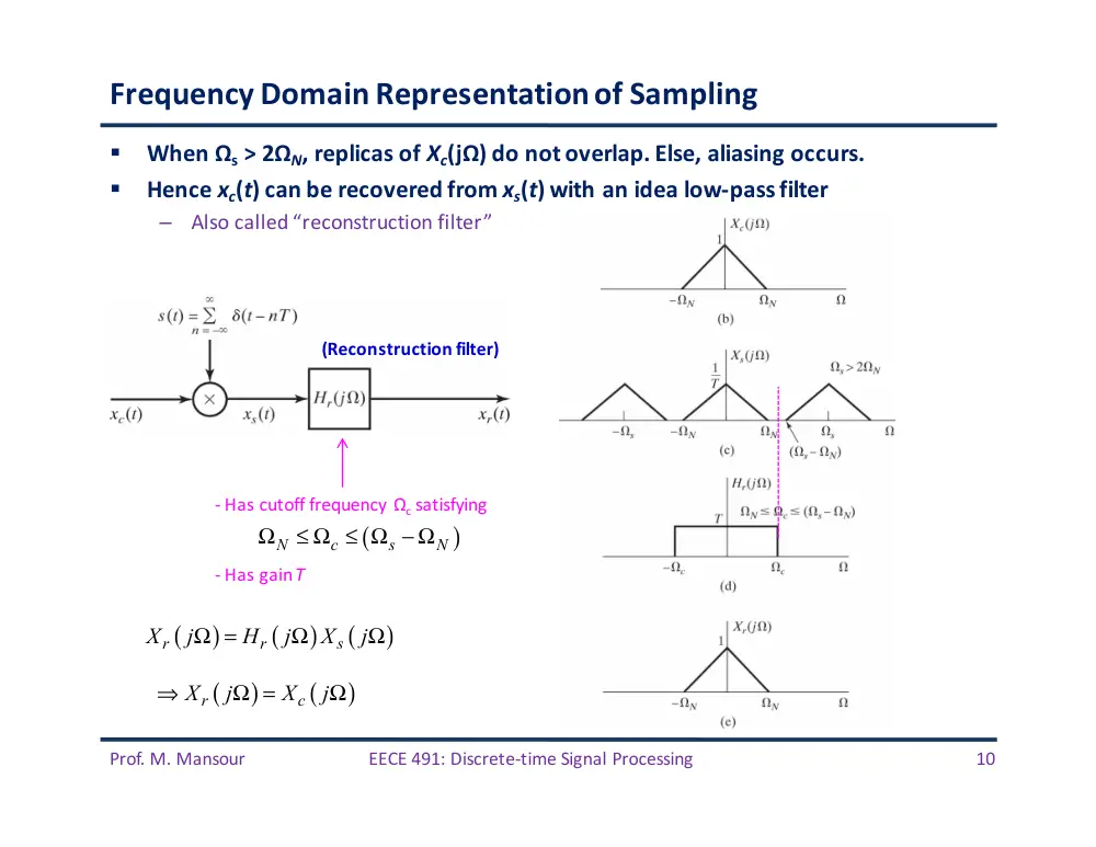
When
Ωs >
2ΩN,
replicas
of
Xc(jΩ)
do
not
overlap.
Else,
aliasing
occurs.
§
Hence
xc(t)
can
be
recovered
from
xs(t)
with
an
idea
low-‐pass
filter
–
Also
called
“reconstruction
filter”
-‐ Has
cutoff
frequency
Ωc satisfying
(
)
N
c
s
N
Ω
≤ Ω ≤ Ω − Ω
-‐ Has
gain
T
(
)
(
)
(
)
r
r
s
X
j
H
j
X
j
Ω =
Ω
Ω
(
)
(
)
r
c
X
j
X
j
⇒
Ω =
Ω
(Reconstruction
filter)
Prof.
M.
Mansour
EECE
491:
Discrete-‐time
Signal
Processing
11
Example
1:
Impact
of
Aliasing
( )
(
)
(
)
(
)
0
0
0
cos
c
c
x
t
t
X
j
πδ
πδ
=
Ω
Ω =
Ω − Ω
+
Ω + Ω
0
0
Two cases:
2
2
s
s
Ω > Ω
Ω < Ω
( )
( )
0
cos
r
c
x
t
x
t
t
⇒
=
=
Ω
( )
( )
(
0 )
cos
r
c
s
x
t
x
t
t
⇒
=
=
Ω − Ω
Prof.
M.
Mansour
EECE
491:
Discrete-‐time
Signal
Processing
12
Frequency
Domain
Representation
of
Sampling
Prof.
M.
Mansour
EECE
491:
Discrete-‐time
Signal
Processing
13
Frequency
Domain
Representation
of
Sampling
§
Relationship
between
(
)
( )
(
)
C.T.F.T
c
c
X
j
x
t
Ω =
(
)
( [ ]
)
=D.T.F.T
X e j
x n
ω
( )
(
) (
)
s
c
n
x
t
x
nT
t
nT
δ
∞
=−∞
=
−
∑
(
)
(
)
j Tn
s
c
n
X
j
x
nT e
∞
− Ω
=−∞
Ω = ∑
[ ]
(
)
c
x n
x
nT
=
(
)
[ ]
j
j n
n
X e
x n e
ω
ω
∞
−
=−∞
= ∑
(
)
(
)
(
)
j
j T
s
T
X
j
X e
X e
ω
ω
Ω
=Ω
Ω =
=
C.T.F.T.
But:
Then
(
)
(
)
(
)
1
s
c
s
k
X
j
X
j
k
T
∞
=−∞
Ω =
Ω − Ω
∑
We
also
proved
(
)
(
)
(
)
1
j T
c
s
k
X e
X
j
k
T
∞
Ω
=−∞
⇒
=
Ω − Ω
∑
OR
(
)
1
2
j
c
k
k
X e
X
j
T
T
T
ω
ω
π
∞
=−∞
⎛
⎞
⎛
⎞
⇒
=
−
∑
⎜
⎟
⎜
⎟
⎝
⎠
⎝
⎠
?
Prof.
M.
Mansour
EECE
491:
Discrete-‐time
Signal
Processing
14
Frequency
Domain
Representation
of
Sampling
§
X(ej𝝎)
is
a
frequency-‐scaled
version
of Xs(j𝛀)
§
Frequency
scaling
specified
by
𝝎 =
𝛀T
§
Equivalent
to
frequency
normalization:
–
Frequency
𝛀s in
Xs(j𝛀)
normalized
to
𝝎 =
2𝜋 in
X(ej𝜔)
Prof.
M.
Mansour
EECE
491:
Discrete-‐time
Signal
Processing
15
Example
2
§
Sample
the
CT
signal
at
T =
1/6000
and
show
F.T.
of
CT
&
DT
signals
§
Solution:
–
Highest
frequency
in
C.T.
signal
𝛀N
=
4000�
–
Nyquist
rate
𝛀S
=
12000𝜋 >
2𝛀
N=
8000�
–
No
aliasing
–
F.T.
( )
cos4000
cx
t
πt
=
(
)
(
)
(
)
4000
4000
Xc
j
πδ
π
πδ
π
Ω =
Ω −
+
Ω +
(
)
(
)
(
)
1
s
c
s
k
X
j
X
j
k
T
∞
=−∞
⇒
Ω =
Ω − Ω
∑
Has
gain
T
Has
cutoff
frequency
𝛀c satisfying
/ 2
c
Ω = Ωs
Prof.
M.
Mansour
EECE
491:
Discrete-‐time
Signal
Processing
16
Example
2
(cont’d)
§
Repeat
for
–
Nyquist
rate
not
satisfied
since
𝛀S
=
12000𝜋
<
2
𝛀N
=
32000𝜋
�
–
Aliasing
occurs
( )
cos16000
cx
t
πt
=
Prof.
M.
Mansour
EECE
491:
Discrete-‐time
Signal
Processing
17
Reconstruction
of
a
Band-‐limited
Signal
from
its
Samples
Prof.
M.
Mansour
EECE
491:
Discrete-‐time
Signal
Processing
18
Reconstruction
of
a
Band-‐limited
Signal
from
its
Samples
§
Given
a
sequence
of
samples
,
can
we
recover
the
original
signal
?
§
First
form
an
impulse
train
in
which
successive
samples
are
assigned
an
area
equal
to
§
Pass
this
signal
thru
an
ideal
low-‐pass
C.T.
filter
with
frequency
response
and
impulse
response
[ ]
x n
( )
[ ] (
)
s
n
x
t
x n
t
nT
δ
∞
=−∞
=
−
∑
cx ( )
t
sx ( )
t
[ ]
x n
(
)
Hr
jΩ
rh ( )
t
( )
[ ]
(
)
r
r
n
x
t
x n h
t
nT
∞
=−∞
=
−
∑
-‐ Hr(j𝛀)
has
cutoff
frequency
𝛀c satisfying
(
)
N
c
s
N
Ω
≤ Ω ≤ Ω − Ω
-‐ Hr(j𝛀)
has
gain
T
-‐
Convenient
choice
of
𝛀c
is
𝛀
s
/2
Prof.
M.
Mansour
EECE
491:
Discrete-‐time
Signal
Processing
19
Reconstruction
of
a
Band-‐limited
Signal
from
its
Samples
§
The
impulse
response
of
the
ideal
LPF
with
cutoff
frequency
𝛀c =
𝛀s
/2
=
𝝅/T
is:
§
Then:
§
Note
that:
–
hr(0)
=
1
–
hr(nT)
=
0,
for
n
=
�1,
�2,
…
–
Then
if
x[n]
=
xr(nT)
è xr(mT)
=
xc(mT)
for
all
integer
values
of
m.
–
Therefore,
reconstructed
signal
xr(t)
has
same
values
as
the
original
signal
xc(t)
at
the
sampling
times,
independently
of
T.
§
The
ideal
LPF
“interpolates”
between
the
impulses
xs(t)
to
construct
xc(t)
( )
[ ]
(
)
(
)
sin
/
/
r
n
t
nT
T
x
t
x n
t
nT
T
π
π
∞
=−∞
−
⎡
⎤
⎣
⎦
= ∑
−
( )
(
)
sin
/
/
r
t T
h
t
t T
π
π
=
Prof.
M.
Mansour
EECE
491:
Discrete-‐time
Signal
Processing
20
Reconstruction
of
a
Band-‐limited
Signal
from
its
Samples
[ ]
(
)
(
)
sin
/
/
t
nT
T
x n
t
nT
T
π
π
−
⎡
⎤
⎣
⎦
−
Prof.
M.
Mansour
EECE
491:
Discrete-‐time
Signal
Processing
21
Ideal
Discrete-‐to-‐Continuous-‐Time
(D/C)
Converter
In
frequency
domain:
( )
[ ]
(
)
r
r
n
x
t
x n h
t
nT
∞
=−∞
=
−
⇒
∑
(
)
[ ]
(
)
(
)
[ ]
(
) (
)
j Tn
r
r
n
j Tn
r
n
j T
r
X
j
x n H
j
e
H
j
x n e
H
j
X e
∞
− Ω
=−∞
∞
− Ω
=−∞
Ω
Ω =
Ω
∑
=
Ω
∑
=
Ω
Prof.
M.
Mansour
EECE
491:
Discrete-‐time
Signal
Processing
22
D.T.
Processing
of
C.T.
Signals
Prof.
M.
Mansour
EECE
491:
Discrete-‐time
Signal
Processing
23
D.T.
Processing
of
C.T.
Signals
(
)
1
2
j
c
k
k
X e
X
j
T
T
T
ω
ω
π
∞
=−∞
⎛
⎞
⎛
⎞
=
−
∑
⎜
⎟
⎜
⎟
⎝
⎠
⎝
⎠
[ ]
(
)
c
x n
x
nT
=
(
)
Xc
jΩ
(
)
j
X e ω
(
)
j
Y e ω
(
)
rY
jΩ
[ ]
h n
(
)
j
H e ω
( )
[ ]
(
)
(
)
sin
/
/
r
n
t
nT
T
y
t
y n
t
nT
T
π
π
∞
=−∞
−
⎡
⎤
⎣
⎦
= ∑
−
(
)
(
) (
)
(
)
/
0
j
j
r
r
TY e
T
Y
j
H
j
Y e
otherwise
π
Ω
Ω
⎧
Ω <
⎪
Ω =
Ω
= ⎨
⎪⎩
(
)
(
) (
)
j
j
j
Y e
H e
X e
ω
ω
ω
=
[ ]
[ ]
[ ]
y n
x n
h n
=
∗
If
DT
system
is
LTI
(
)
(
)
(
)
r
eff
c
Y
j
H
j
X
j
Ω =
Ω
Ω
Prof.
M.
Mansour
EECE
491:
Discrete-‐time
Signal
Processing
24
D.T.
Processing
of
C.T.
Signals:
D.T.
System
is
LTI
§
Overall
C.T.
system
is
equivalent
to
an
LTI
system
whose
effective
frequency
response
is
–
Conditions:
• Input
signal
is
band-‐limited
+
sampling
rate
>
Nyquist
rate
(to
avoid
aliasing)
• C/D
is
ideal
• D.T.
system
is
LTI
• D/C
is
ideal
§
Proof:
(
)
(
) (
)
D.T. system is LTI
j
j
j
Y e
H e
X e
ω
ω
ω
⇒
=
(
)
(
)
(
)
r
eff
c
Y
j
H
j
X
j
Ω =
Ω
Ω
(
)
(
) (
)
(
) (
) (
)
D/C is ideal
j T
j T
j T
r
r
r
Y
j
H
j
Y e
H
j
H e
X e
Ω
Ω
Ω
⇒
Ω =
Ω
=
Ω
Relating
X(ejΩT)
to
Xc(jΩ)
thru
sampling
�
(
)
(
) (
)
1
2
j T
r
r
c
k
k
Y
j
H
j
H e
X
j
T
T
π
∞
Ω
=−∞
⎛
⎞
⎛
⎞
Ω =
Ω
Ω −
∑
⎜
⎟
⎜
⎟
⎝
⎠
⎝
⎠
(
)
input bandlimited
0 for
/
Xc
j
π T
⇒
Ω =
Ω >
(
)
ideal
with cutoff
/
, gain 1/
r
c
H
j
T
T
π
Ω
Ω =
+
(
)
(
)
(
)
/
0
/
j
j
c
r
H e
X
e
T
Y
j
T
π
π
Ω
Ω
⎧
Ω <
⎪
Ω = ⎨
Ω ≥
⎪⎩
(
)
(
)
(
)
r
eff
c
Y
j
H
j
X
j
Ω =
Ω
Ω
(
)
(
)
/
0
/
j
eff
H e
T
H
j
T
π
π
Ω
⎧
Ω <
⎪
Ω = ⎨
Ω ≥
⎪⎩
�
Prof.
M.
Mansour
EECE
491:
Discrete-‐time
Signal
Processing
25
Example
3
§
Consider
a
discrete-‐time
LTI
system
with
§
For
band-‐limited
inputs
sampled
above
the
Nyquist
rate,
the
overall
C.T.
system
will
behave
as
an
LTI
C.T.
system
with
frequency
response
(
)
1
0
c
j
c
H e ω
ω
ω
ω
ω
<
⎧
= ⎨
≥
⎩
(
)
1
or
/T
0
or
/T
c
c
eff
c
c
T
H
j
T
ω
ω
ω
ω
Ω
<
Ω <
⎧
Ω = ⎨
Ω
≥
Ω ≥
⎩
periodic
Has
cutoff
frequency
ωc/T
D.T.
Filter
C.T.
Filter
Prof.
M.
Mansour
EECE
491:
Discrete-‐time
Signal
Processing
26
Example
3
(cont’d)
(a) F.T. of a band-limited input signal.
(b) F.T. of sampled input plotted as a
function of C.T. frequency Ω.
(c) F.T. X (ejω) of sequence of samples and
frequency response H(ejω) of D.T. system
plotted versus ω.
(d) F.T. of output of D.T. system.
(e) F.T. of output of D.T. system and
frequency response of ideal reconstruction
filter plotted versus Ω.
(f) F.T. of output.
No aliasing: (
)
2
N
c
T
π
ω
− Ω
≥
Prof.
M.
Mansour
EECE
491:
Discrete-‐time
Signal
Processing
27
Example
3
(cont’d)
§
The
effective
filter
below
still
holds
even
if
aliasing
occurs,
provided
aliased
or
distorted
components
are
eliminated
by
D.T.
filter
H(ej𝝎)
(
)
1
or
/T
0
or
/T
c
c
eff
c
c
T
H
j
T
ω
ω
ω
ω
Ω
<
Ω <
⎧
Ω = ⎨
Ω
≥
Ω ≥
⎩
No aliasing: (
)
2
N
c
T
π
ω
− Ω
≥
Nyquist condition: (
)
2
N
N
T
T
π − Ω
≥ Ω
Prof.
M.
Mansour
EECE
491:
Discrete-‐time
Signal
Processing
28
Example
4:
D.T.
Implementation
of
an
Ideal
C.T.
Differentiator
§
Ideal
C.T.
differentiator
is
defined
by
§
We
want
to
realize
this
filter
using
a
C/D
converter,
D.T.
filter,
D/C
converter
–
Inputs
are
band-‐limited
–
Equivalent
effective
C.T.
filter
becomes
§
D.T.
filter
then
become
§
Impulse
response:
( )
( )
c
c
d
y
t
x
t
= dt
⎡
⎤
⎣
⎦
(
)
Hc
j
j
Ω = Ω
(
)
(
),
/
,
/T
0,
/T
0,
/
j
eff
H e
T
j
H
j
T
π
π
π
π
Ω
⎧
Ω <
Ω
Ω <
⎧
⎪
Ω =
=
⎨
⎨
Ω ≥
Ω ≥
⎩
⎪⎩
(
)
,
j
j
H e
T
ω
ω
ω
π
=
<
[ ]
2
1
2
cos
sin
0
0
cos
0
j n
j
h n
e
d
T
n
n
n
n T
n
n
n
nT
π
ω
π
ω
ω
π
π
π
π
π
π
−
⎛
⎞
=
∫ ⎜
⎟
⎝
⎠
−
=
=
⎧⎪
= ⎨
≠
⎪⎩
Apply
'Hôpital's rule
Prof.
M.
Mansour
EECE
491:
Discrete-‐time
Signal
Processing
29
Example
4:
D.T.
Implementation
of
an
Ideal
C.T.
Differentiator
(
)
,
/T
0,
/T
eff
j
H
j
π
π
Ω
Ω <
⎧
Ω = ⎨
Ω ≥
⎩
(
)
,
j
j
H e
T
ω
ω
ω
π
=
<
Prof.
M.
Mansour
EECE
491:
Discrete-‐time
Signal
Processing
30
Impulse
Invariance
(Revisited)
§
Given
a
desired
C.T.
we
wish
to
implement
using
a
D.T.
system
as
follows:
Prof.
M.
Mansour
EECE
491:
Discrete-‐time
Signal
Processing
31
Impulse
Invariance
(Revisited)
§
With
Hc(j�)
band-‐limited,
we
choose
H(ej�)
so
that:
§
What
is
resulting
relationship
between
hc(t)
and
h[n]?
–
h[n]
is
a
scaled,
sampled
version
of hc(t),
under
the
impulse
invariance
condition
(
)
(
)
(
)
(
)
/
,
eff
c
j
c
H
j
H
j
H e
H
j
T
ω
ω
ω
π
Ω =
Ω
⇒
=
<
Also
(
)
0,
/
Hc
j
π T
Ω =
Ω ≥
[ ]
(
)
if
c
h n
h
nT
=
(
)
1
2
then
j
c
k
k
H e
H
j
T
T
T
ω
ω
π
∞
=−∞
⎛
⎞
⎛
⎞
=
−
∑
⎜
⎟
⎜
⎟
⎝
⎠
⎝
⎠
(
)
But:
0,
/
Hc
j
π T
Ω =
Ω ≥
(
)
1
Therefore,
,
j
c
H e
H
j
T
T
ω
ω
ω
π
⎛
⎞
=
<
⎜
⎟
⎝
⎠
(
)
[ ]
[ ]
(
)
So to get
for
, we scale
so that
j
c
c
H e
H
j
h n
h n
T h
nT
T
ω
ω
ω
π
⎛
⎞
=
<
=
⋅
⎜
⎟
⎝
⎠
Prof.
M.
Mansour
EECE
491:
Discrete-‐time
Signal
Processing
32
Example
5:
D.T.
LPF
Obtained
by
Impulse
Invariance
§
Design
an
ideal
D.T.
LPF
with
cutoff
frequency
𝛚c
<
𝝅 by
sampling
a
C.T.
LPF
with
cutoff
frequency
𝛀c.
§
Solution:
We
have
§
The
cutoff
frequency
𝛚c
is
related
to
𝛀c by
§
Impulse
response
of
C.T.
LPF
is
§
Using
impulse
invariance,
we
obtain
(
)
1,
0,
c
c
c
H
j
Ω < Ω
⎧
Ω = ⎨
Ω ≥ Ω
⎩
c
cT
ω = Ω
( )
sin
c
c
t
h
t
πt
Ω
=
[ ]
(
)
(
)
(
)
sin
sin
c
c
c
h n
T h
nT
nT
T
nT
n
n
π
ω
π
=
⋅
Ω
=
=
(
)
1,
0,
c
j
c
H e ω
ω
ω
ω
ω
π
<
⎧
⇒
= ⎨
≤
≤
⎩
Prof.
M.
Mansour
EECE
491:
Discrete-‐time
Signal
Processing
33
C.T.
Processing
of
D.T.
Signals
Prof.
M.
Mansour
EECE
491:
Discrete-‐time
Signal
Processing
34
C.T.
Processing
of
D.T.
Signals
§
From
definitions
of
D/C
and
C/D,
we
must
have
Xc(j𝛀)=0,
Yc(j𝛀)=0
for
|𝛀|
≥ 𝝅/T
§
In
frequency
domain:
( )
[ ]
(
)
(
)
sin
/
/
c
n
t
nT
T
x
t
x n
t
nT
T
π
π
∞
=−∞
−
⎡
⎤
⎣
⎦
= ∑
−
(
)
(
)
(
)
(
)
(
)
(
)
,
/
1
,
j T
c
c
c
c
j
c
X
j
TX e
T
Y
j
H
j
X
j
Y e
Y
j
T
T
ω
π
ω
ω
π
Ω
Ω =
Ω <
Ω =
Ω
Ω
⎛
⎞
=
<
⎜
⎟
⎝
⎠
(
)
,
j
c
H e
H
j T
ω
ω
ω
π
⎛
⎞
⇒
=
<
⎜
⎟
⎝
⎠
(
)
(
)
or
,
/
j T
Hc
j
H e
T
π
Ω
Ω =
Ω <
Prof.
M.
Mansour
EECE
491:
Discrete-‐time
Signal
Processing
35
Example
6:
Non-‐Integer
Delay
§
Consider
a
D.T.
system
with
frequency
response:
§
We
seek
an
interpretation
in
the
C.T.
domain.
§
Choose
a
C.T.
filter
with
response:
–
Here,
xc(t)
is
band-‐limited
interpolation
of
x[n];
y[n]
is
obtained
by
sampling
yc(t)
§
Example:
if
𝚫=1/2,
y[n]
would
be
the
band-‐limited
interpolation
halfway
between
the
input
sequence
values.
(
)
[ ]
[
]
,
,
not necessarily an integer
j
j
H e
e
y n
x n
ω
ω
ω
π
−
Δ
=
<
=
− Δ
Δ
(
)
(
)
( )
(
)
j T
j T
c
c
c
H
j
H e
e
y
t
x
t
T
Ω
− Ω Δ
Ω =
=
=
− Δ
[ ]
(
)
(
)
[ ]
(
)
(
)
[ ]
(
)
(
)
sin
/
/
sin
c
c
k
t nT
k
y n
y
nT
x
nT
T
t
T
kT
T
x k
t
T
kT
T
n
k
x k
n
k
π
π
π
π
∞
=−∞
=
∞
=−∞
=
=
− Δ
− Δ −
⎡
⎤
⎣
⎦
= ∑
− Δ −
−
− Δ
⎡
⎤
⎣
⎦
= ∑
−
− Δ
[ ]
(
)
(
)
sin
n
x n
n
π
π
− Δ
⎡
⎤
⎣
⎦
≡
∗
− Δ
Prof.
M.
Mansour
EECE
491:
Discrete-‐time
Signal
Processing
36
Example
6:
Non-‐Integer
Delay
(a) C.T. processing of the D.T. sequence (b) can produce a new sequence with a “half-
sample” delay.
Prof.
M.
Mansour
EECE
491:
Discrete-‐time
Signal
Processing
37
Example
7:
Moving-‐Average
System
with
Non-‐Integer
Delay
§
For
an
(M+1)-‐point
causal
moving
average
system,
we
have
§
Can
represent
as
a
cascade
of
two
systems:
§
If
M is
even,
then
linear
phase
term
is
an
integer
delay
§
If
M is
odd,
then
linear
phase
term
is
a
non-‐integer
delay
(integer-‐plus-‐one-‐half)
–
y[n]
is
then
the
band-‐limited
interpolation
of
w[n]
–
Followed
by
a
C.T.
delay
of
MT/2,
where
T is
sampling
period
of
D/C
interpolation
of
w[n])
–
Followed
by
C/D
conversion
with
sampling
period
T.
(
)
(
)
(
)
/2
sin
1 / 2
1
,
1
sin
/ 2
j
j M
M
H e
e
M
ω
ω
ω
ω
π
ω
−
+
⎡
⎤
⎣
⎦
=
<
+
Prof.
M.
Mansour
EECE
491:
Discrete-‐time
Signal
Processing
38
Example
7
(cont’d)
Illustration
of
moving-‐average
filtering.
(a)
Input
signal
x[n]
=
cos(0.25πn).
(b)
Corresponding
output
of
six-‐point
moving-‐average
filter.
M
=
5
Prof.
M.
Mansour
EECE
491:
Discrete-‐time
Signal
Processing
39
Example
7
(cont’d)
[ ]
(
)
0.25
0.25
1
1
cos 0.25
2
2
j
n
j
n
x n
n
e
e
π
π
π
−
=
=
+
(
)
(
)
(
)
/2
sin
1 / 2
1
,
1
sin
/ 2
j
j M
M
H e
e
M
ω
ω
ω
ω
π
ω
−
+
⎡
⎤
⎣
⎦
=
<
+
[ ]
(
)
(
)
(
)
0.25
0.25
0.25
0.25
1
1
2
2
0.308cos 0.25
2.5
j
j
n
j
j
n
y n
H e
e
H e
e
n
π
π
π
π
π
−
−
=
+
=
−
⎡
⎤
⎣
⎦
Moving
average
filter:
•
Reduces
amplitude
of
input
•
Introduces
a
phase
shift
corresponding
to
2.5
samples
of
delay