
MECH 314 Problems 1, Spring 2014
American University of Beirut · Introduction to Fluids Engineering · 12 pages




Showing the first 10 of 12 pages. Download the PDF to see all of it.
More MECH 314 files
Show the text of this problems
MECH 660 Advanced Fluid Mechanics
March 17, 2004
American University of Beirut, Spring 2004
Handout # PS2 Solution
Problem Set 2 Solution: Inviscid Flow
“Advanced Fluid Mechanics Problems” by Shapiro and Sonin
Problems 4.4, 4.7, 4.8, 4.9, 4.10, 4.13, 4.18, 4.19, 4.21, 4.23, 4.24, 4.28.
Problem 4.4
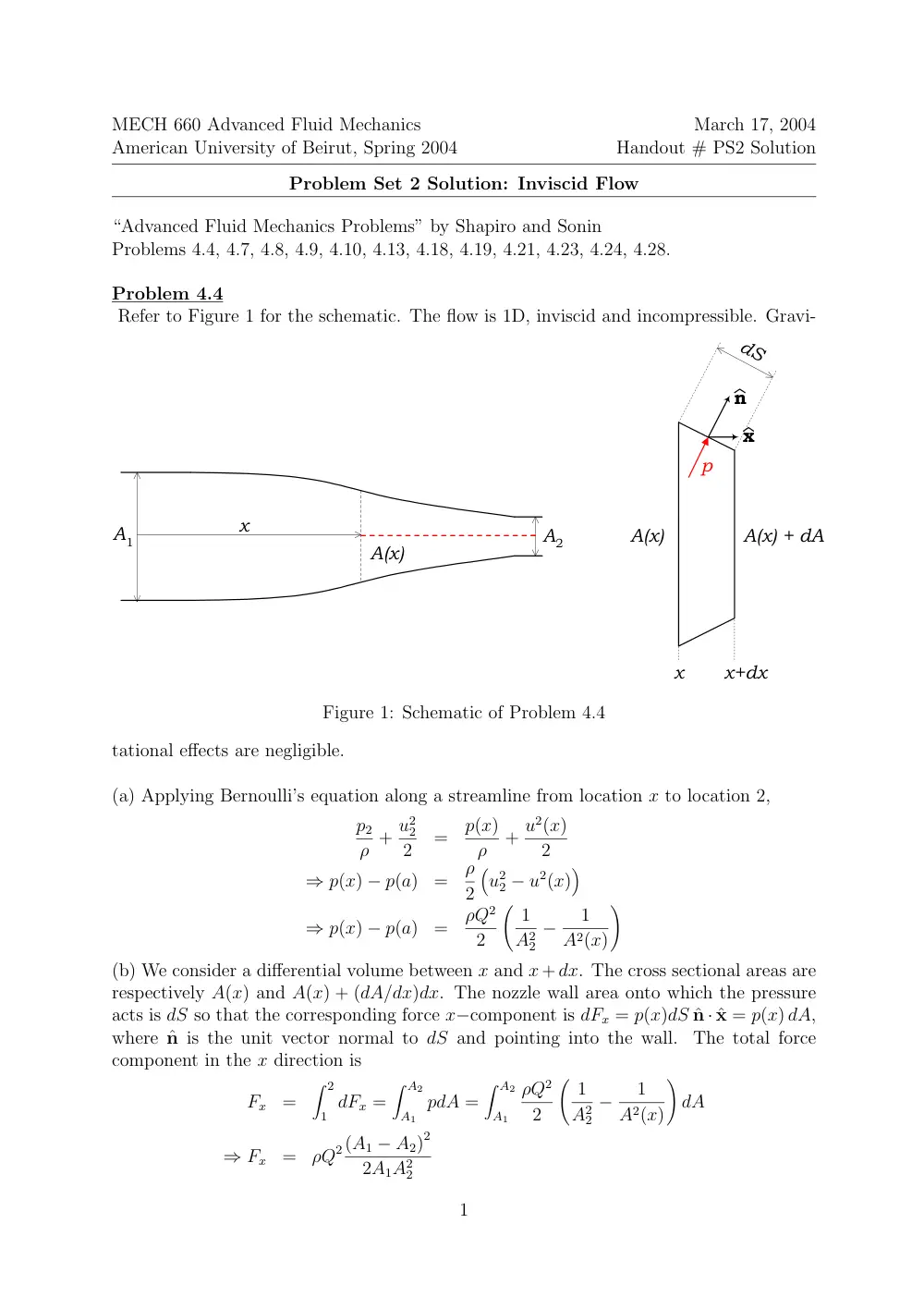
Refer to Figure 1 for the schematic. The flow is 1D, inviscid and incompressible. Gravi-
A1
A(x)
x
A2
x
x+dx
A(x)
A(x) + dA
p
n
x
dS
Figure 1: Schematic of Problem 4.4
tational effects are negligible.
(a) Applying Bernoulli’s equation along a streamline from location x to location 2,
p2
ρ + u2
2
2
=
p(x)
ρ
+ u2(x)
2
⇒ p(x) − p(a)
=
ρ
2
�
u2
2 − u2(x)
�
⇒ p(x) − p(a)
=
ρQ2
2
� 1
A2
2
−
1
A2(x)
�
(b) We consider a differential volume between x and x+dx. The cross sectional areas are
respectively A(x) and A(x) + (dA/dx)dx. The nozzle wall area onto which the pressure
acts is dS so that the corresponding force x−component is dFx = p(x)dS ˆn · ˆx = p(x) dA,
where ˆn is the unit vector normal to dS and pointing into the wall.
The total force
component in the x direction is
Fx
=
� 2
1 dFx =
� A2
A1
pdA =
� A2
A1
ρQ2
2
� 1
A2
2
−
1
A2(x)
�
dA
⇒ Fx
=
ρQ2(A1 − A2)2
2A1A2
2
1
(c) The product p dA has always the same sign.
• If A ↗, dA > 0 ⇒ u ↘⇒ p ↗
• If A ↘, dA < 0 ⇒ u ↗⇒ p ↘
2
Problem 4.7
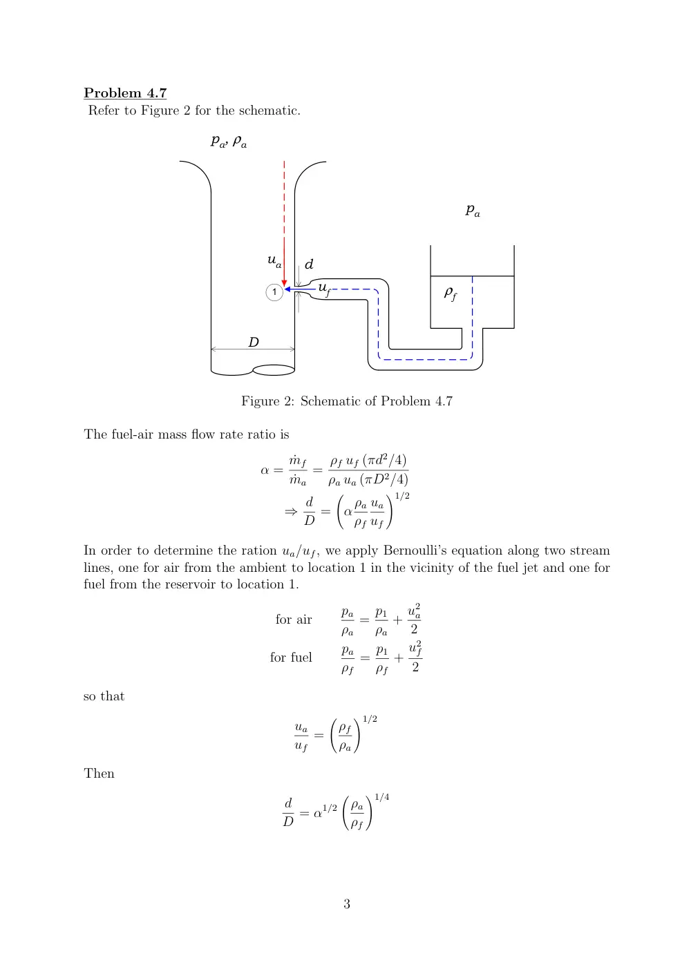
Refer to Figure 2 for the schematic.
D
d
pa, ρa
pa
ρf
ua
uf
1
Figure 2: Schematic of Problem 4.7
The fuel-air mass flow rate ratio is
α = ˙mf
˙ma
= ρf uf (πd2/4)
ρa ua (πD2/4)
⇒ d
D =
�
αρa
ρf
ua
uf
�1/2
In order to determine the ration ua/uf, we apply Bernoulli’s equation along two stream
lines, one for air from the ambient to location 1 in the vicinity of the fuel jet and one for
fuel from the reservoir to location 1.
for air
pa
ρa
= p1
ρa
+ u2
a
2
for fuel
pa
ρf
= p1
ρf
+ u2
f
2
so that
ua
uf
=
�ρf
ρa
�1/2
Then
d
D = α1/2
�ρa
ρf
�1/4
3
Problem 4.8
Refer to Figure 3 for the schematic. The flow is inviscid and incompressible.
F
D1
D2
1
2
u2
u1
Figure 3: Schematic of Problem 4.8
(a) We apply Bernoulli’s equation along a stream line starting from location 1 the top of
the bellows and ending at location 2 at the nozzle exit.
p1
ρ + u2
1
2
=
pa
ρ + u2
2
ρ
⇒ p1 − pa
=
ρ
2
�
u2
2 − u2
1
�
⇒ F
A1
=
ρ
2
�
u2
2 − u2
1
�
(1)
Next we apply the conservation of mass in integral form for a control volume that is
moving with the piston
d
dt (ρV) + ρ u2
πD2
2
4
= 0
⇒ u2 = − 4
πD2
2
dV
dt
By also applying conservation of mass in integral form for fixed control volume we find
the relation
u1 D2
1 = u2 D2
2 ⇒ u1 = −
�D2
D1
�2
4
πD2
2
dV
dt
4
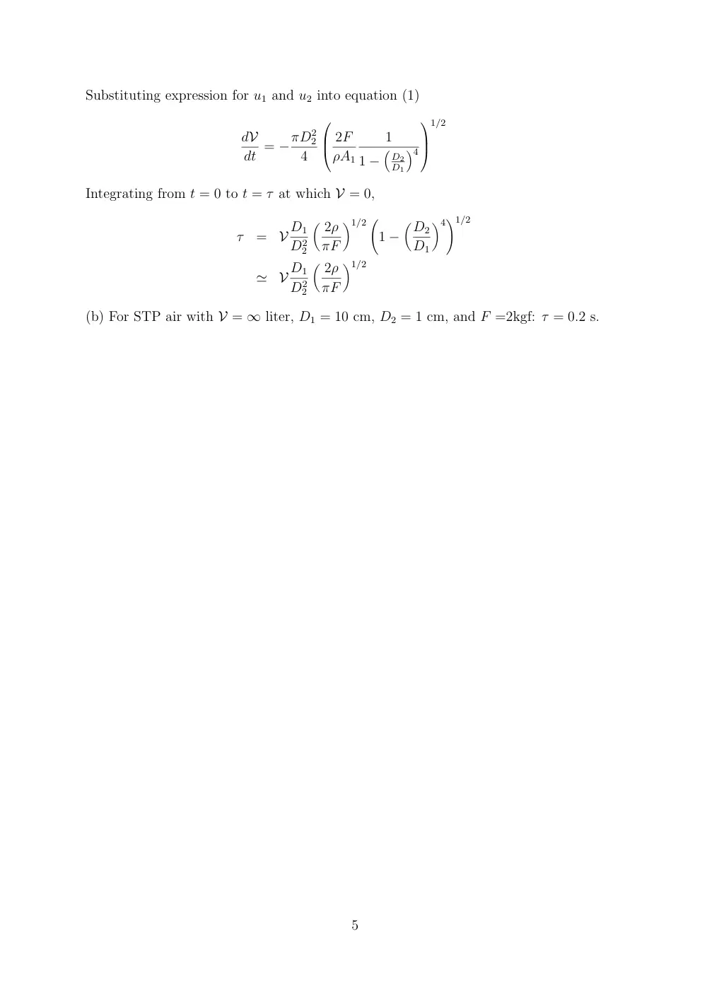
Substituting expression for u1 and u2 into equation (1)
dV
dt = −πD2
2
4
2F
ρA1
1
1 −
�
D2
D1
�4
1/2
Integrating from t = 0 to t = τ at which V = 0,
τ
=
V D1
D2
2
� 2ρ
πF
�1/2 �
1 −
�D2
D1
�4�1/2
≃
V D1
D2
2
� 2ρ
πF
�1/2
(b) For STP air with V = ∞ liter, D1 = 10 cm, D2 = 1 cm, and F =2kgf: τ = 0.2 s.
5
Problem 4.9
Refer to Figure 4 for the schematic. The flow is inviscid and steady.
1
2
3
h
Ta
Ta + ∆T
H
d
g
Figure 4: Schematic of Problem 4.9
(a) We apply Bernoulli’s equation along the stream line 2 − 3:
� 3
2 dp +
� 3
2 ρ g z ds +
� 3
2
1
2ρ u2 ds = 0
⇒ (p3 − p2) + ρH g h + 1
2u2
3 ≃ 0
⇒ g h (ρa − ρH) ≃ 1
2ρH u2
3
⇒ u3 ≃
�
2 g h
� ρa
ρH
− 1
��1/2
⇒ u3 ≃
�
2 g h∆T
Ta
�1/2
6
where p3 − p2 = −ρa g h, ρ2 = ρ3 = ρH, u2
2 << u2
3, and pa = ρaRTa = ρHR (Ta + ∆T).
(b) In the case the cap is closed,
� 3
2 dp +
� 3
2 ρ g z ds +
� 3
2
1
2ρ u2 ds = 0
⇒ (p3 − p2) + ρH g h ≃ 0
⇒ p3 ≃ pa − ρHg h
⇒ p3 − p3a ≃ g h (ρa − ρH)
⇒ (∆p)cap ≃ ρa g h
∆T
Ta + ∆T
where p2 = pa, p3a = pa − ρa g h, ρ2 = ρ3 = ρH, u2 ≃ 0, u3 = 0 and pa = ρaRTa =
ρHR (Ta + ∆T).
7
Problem 4.10
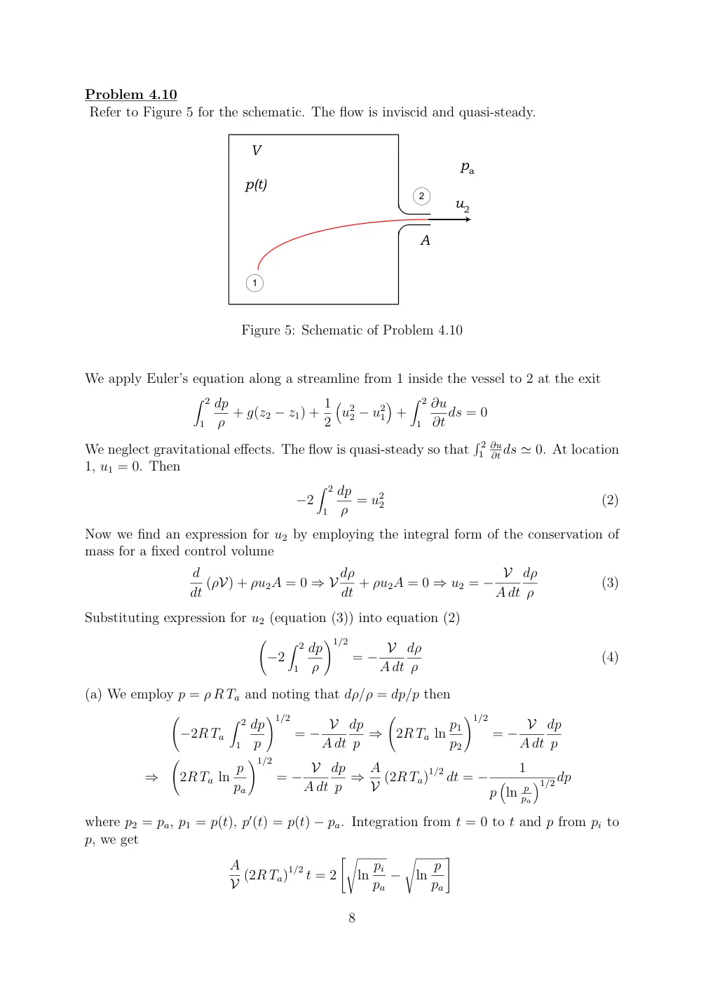
Refer to Figure 5 for the schematic. The flow is inviscid and quasi-steady.
1
2
pa
V
p(t)
A
u2
Figure 5: Schematic of Problem 4.10
We apply Euler’s equation along a streamline from 1 inside the vessel to 2 at the exit
� 2
1
dp
ρ + g(z2 − z1) + 1
2
�
u2
2 − u2
1
�
+
� 2
1
∂u
∂t ds = 0
We neglect gravitational effects. The flow is quasi-steady so that
� 2
1
∂u
∂t ds ≃ 0. At location
1, u1 = 0. Then
−2
� 2
1
dp
ρ = u2
2
(2)
Now we find an expression for u2 by employing the integral form of the conservation of
mass for a fixed control volume
d
dt (ρV) + ρu2A = 0 ⇒ V dρ
dt + ρu2A = 0 ⇒ u2 = − V
A dt
dρ
ρ
(3)
Substituting expression for u2 (equation (3)) into equation (2)
�
−2
� 2
1
dp
ρ
�1/2
= − V
A dt
dρ
ρ
(4)
(a) We employ p = ρ R Ta and noting that dρ/ρ = dp/p then
�
−2R Ta
� 2
1
dp
p
�1/2
= − V
A dt
dp
p ⇒
�
2R Ta ln p1
p2
�1/2
= − V
A dt
dp
p
⇒
�
2R Ta ln p
pa
�1/2
= − V
A dt
dp
p ⇒ A
V (2R Ta)1/2 dt = −
1
p
�
ln p
pa
�1/2dp
where p2 = pa, p1 = p(t), p′(t) = p(t) − pa. Integration from t = 0 to t and p from pi to
p, we get
A
V (2R Ta)1/2 t = 2
��
ln pi
pa
−
�
ln p
pa
�
8
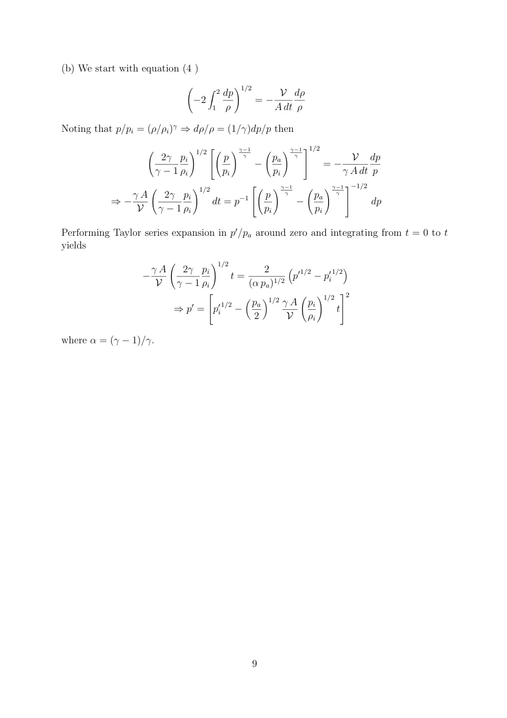
(b) We start with equation (4 )
�
−2
� 2
1
dp
ρ
�1/2
= − V
A dt
dρ
ρ
Noting that p/pi = (ρ/ρi)γ ⇒ dρ/ρ = (1/γ)dp/p then
� 2γ
γ − 1
pi
ρi
�1/2
� p
pi
� γ−1
γ
−
�pa
pi
� γ−1
γ
1/2
= −
V
γ A dt
dp
p
⇒ −γ A
V
� 2γ
γ − 1
pi
ρi
�1/2
dt = p−1
� p
pi
� γ−1
γ
−
�pa
pi
� γ−1
γ
−1/2
dp
Performing Taylor series expansion in p′/pa around zero and integrating from t = 0 to t
yields
−γ A
V
� 2γ
γ − 1
pi
ρi
�1/2
t =
2
(α pa)1/2
�
p′1/2 − p′
i
1/2�
⇒ p′ =
p′
i
1/2 −
�pa
2
�1/2 γ A
V
�pi
ρi
�1/2
t
2
where α = (γ − 1)/γ.
9
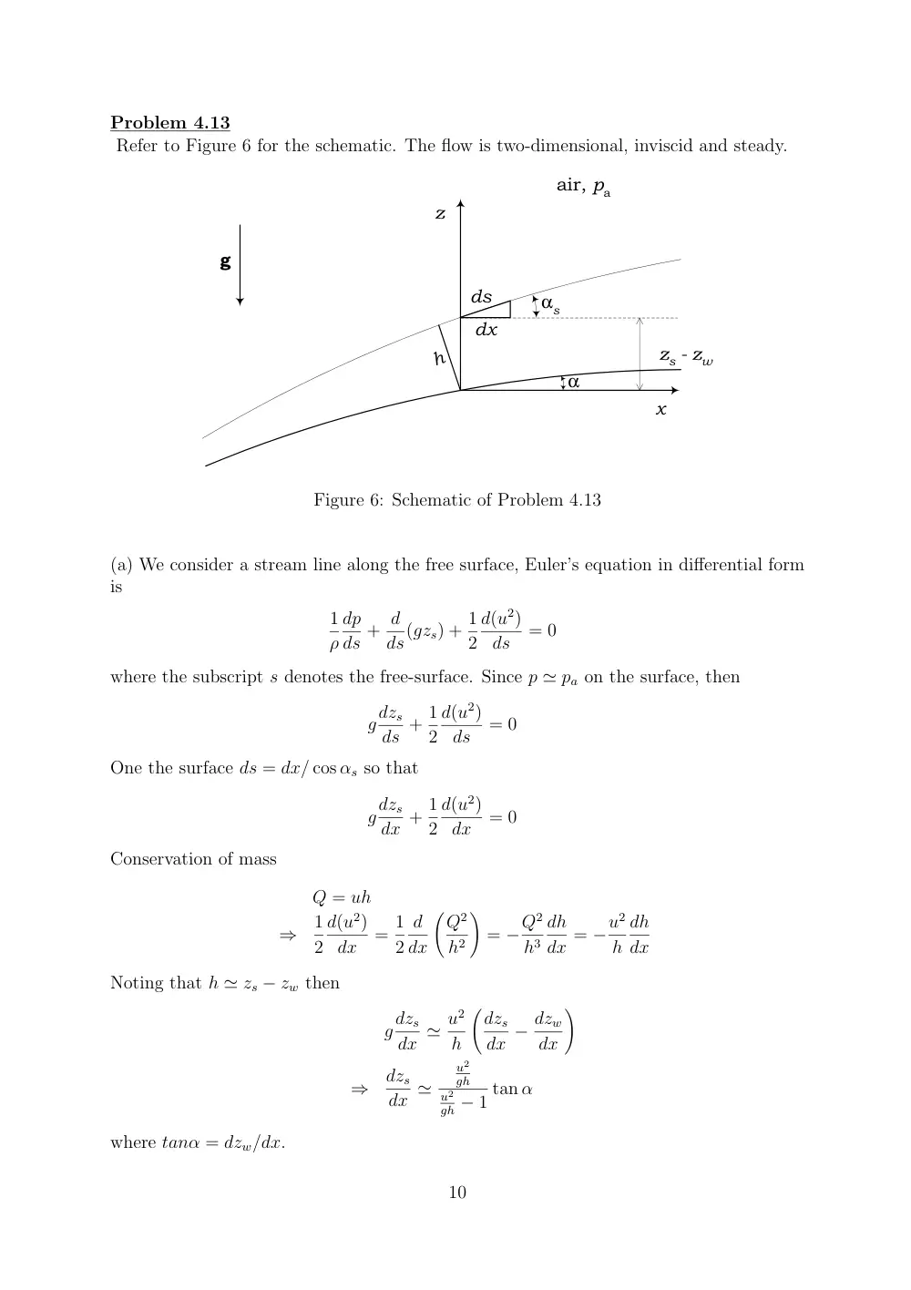
Problem 4.13
Refer to Figure 6 for the schematic. The flow is two-dimensional, inviscid and steady.
g
air, pa
z
x
ds
dx
αs
α
zs - zw
h
Figure 6: Schematic of Problem 4.13
(a) We consider a stream line along the free surface, Euler’s equation in differential form
is
1
ρ
dp
ds + d
ds(gzs) + 1
2
d(u2)
ds
= 0
where the subscript s denotes the free-surface. Since p ≃ pa on the surface, then
gdzs
ds + 1
2
d(u2)
ds
= 0
One the surface ds = dx/ cos αs so that
gdzs
dx + 1
2
d(u2)
dx
= 0
Conservation of mass
Q = uh
⇒
1
2
d(u2)
dx
= 1
2
d
dx
�Q2
h2
�
= −Q2
h3
dh
dx = −u2
h
dh
dx
Noting that h ≃ zs − zw then
gdzs
dx ≃ u2
h
�dzs
dx − dzw
dx
�
⇒
dzs
dx ≃
u2
gh
u2
gh − 1 tan α
where tanα = dzw/dx.
10
A
Vorticity form of Euler’s equation
Euler’s equation in differential form is
∂u
∂t + (u · ∇) u = −1
ρ∇p + g
We invoke the identity
u × (∇ × u) = 1
2∇ (u · u) − (u · ∇) u
Noting that ω = ∇ × u then
∂u
∂t − u × ω = −1
ρ∇p − ∇(gz) − 1
2∇|u|2
Next we take the curl of the above equation
∂ω
∂t − ∇ × u × ω = −∇ ×
�1
ρ∇p
�
We invoke another identity
∇ × u × ω = u(∇ · ω) + (ω · ∇)u − ω(∇ · u) − (u · ∇)ω
Noting that ∇ · ω = 0 and ∇ · u = − 1
ρ
Dρ
Dt from the continuity, then
∂ω
∂t + (u · ∇)ω = (ω · ∇)u + ω
ρ
Dρ
Dt − ∇ ×
�1
ρ∇p
�
Dω
Dt − ω
ρ
Dρ
Dt = (ω · ∇)u − ∇ ×
�1
ρ∇p
�
We invoke the identity
∇ × (aA) = a(∇ × A) + (∇a) × A
so that
∇ ×
�1
ρ∇p
�
= 1
ρ(∇ × ∇p) + ∇
�1
ρ
�
× ∇p = − 1
ρ2∇ρ × ∇p
So that
Dω
Dt − ω
ρ
Dρ
Dt = (ω · ∇)u + 1
ρ2∇ρ × ∇p
Noting that
Dω
Dt − ω
ρ
Dρ
Dt = ρ D
Dt
�ω
ρ
�
Then
ρ D
Dt
�ω
ρ
�
= (ω · ∇)u + 1
ρ2∇ρ × ∇p + ∇ × Fb
(17)
where body force Fb was included in the equation.
Analysis of equation (17)
22
• If the body force is conservative (∇ × Fb = 0) and the flow is incompressible, then
Dω
Dt = (ω · ∇)u
(18)
• If additionally the flow is steady
(ω · ∇)u = 0
(19)
• If the body force is conservative (∇×Fb = 0) and the flow is barotropic (∇ρ×∇p =
0), then
D
Dt
�ω
ρ
�
=
�ω
ρ · ∇
�
u
(20)
23