
MECH 314 Problems 7, Spring 2014
American University of Beirut · Introduction to Fluids Engineering · 9 pages

More MECH 314 files
Show the text of this problems
MECH 411 Introduction to Fluid Mechanics
Dec 11, 2004
American University of Beirut, Fall 2004-2005
Handout # PS4
Problem Set 4 Solution
Textbook: 4.17, 4.21, 4.37, 4.41, 4.43, 4.53, 4.60, 4.83
1
Problem 4.17
(a) The flow is two-dimensional, incompressible, and steady. Given u(x, y) we are asked
to find v(x, y). We employ the continuity (conservation of mass) equation in differential
form
Dρ
Dt + u · ∇u = 0
For incompressible 2D flow, we get
∂u
∂x + ∂v
∂y = 0
⇒
∂v
∂y = −∂u
∂x = −∂u
∂δ
∂δ
∂x
⇒
∂v
∂y = −U
�
−2y
δ2 + 2y2
δ3
� 1
2Cx−1/2
Integrating from y = 0 to y and noting that δ = δ(x) and using the no slip condition:
v(y = 0) = 0, then
� y
0
∂v
∂y dy =
� y
0 −U
�
−2y
δ2 + 2y2
δ3
� 1
2Cx−1/2 dy
⇒
v(x, y) = −U
�
−y2
δ2 + 2y3
3δ3
� 1
2Cx−1/2
⇒
v(x, y) = U
�y2
δ2 − 2y3
3δ3
� 1
2
δ
x
It can be shown that v is maximum where ∂u/∂y = 0 leading to y∗ = δ so that
vmax = U
6
δ
x
For U = 3 m/s, δ = 1.1 cm, and x = 1 m, we get vmax = 0.0055 m/s.
2
Problem 4.21
The flow is steady and 1D. The speed of sound is as = 340 m/s. The objective is to find
(De/D0)min to neglect compressibility effects for (a) V0 = 10 m/s and (b) V0 = 30 m/s.
The incompressibility assumption is valid for M < 0.3, where the Mach number is M ≡
V/as. We assume that the flow is incompressible and later we find the condition that has
to be satisfied. So for an incompressible, steady, 1D flow the continuity equation reduces
to
ρ0V0A0 = ρeVeAe
with ρ0 = ρe, A0 = πD2
0/4, Ae = πD2
e/4, then
V0D2
0 = VeD2
e
Assume that the speed of sound does not change (what does that mean for an ideal gas
knowing that as = √γRT ?) then
�De
D0
�2
=
V0
asMe
Incompressibility implies that Me < 0.3 so that
�De
D0
�2
>
V0
0.3as
Therefore the minimum value of De/D0 is
�De
D0
�
min
=
� V0
0.3as
�1/2
(a) With as = 340 m/s, V0 = 10 m/s, we get (De/D0)min = 0.313
(b) With as = 340 m/s, V0 = 30 m/s, we get (De/D0)min = 0.542
So for higher inlet speed, the outer diameter must be larger.
3
Problem 4.37
The flow is fully developed, i.e. ∂w/∂z = 0, also u = 0, v = 0. The objective is to find
w(x) given that no pressure gradient is applied and the flow is driven by gravity. We
assume also that the flow is incompressible (liquid) and steady.
We employ the momentum equation
ρDu
Dt = −∇p + µ ∇2u + ρg
Since u and v are zero, then we need only the z component of the momentum equation
ρDw
Dt = −∂p
∂z + µ
�∂2w
∂x2 + ∂2w
∂y2 + ∂2w
∂z2
�
− ρg
Noting that Dw/Dt = ∂w/∂t + u ∂w/∂x + v ∂w/∂y + w ∂w/∂y. With ∂()/∂t = 0, u = 0,
v = 0 and ∂w/∂z = 0 (fully developed), then Dw/Dt = 0. Also with w = w(x) we get
∂2w/∂y2 = ∂2w/∂z2 = 0. Finally with no pressure gradient, the equation governing w
reduced to
µ∂2w
∂x2 − ρg = 0
Integrating we get
w(x) = ρg
2µx2 + C1x + C2
where the constants C1 and C2 are determined by the no-slip boundary conditions at the
walls:
(a) w = 0 at x = −h and
(b) w = 0 at x = h
We get C1 = 0 and C2 = −ρg/2µ, then
w(x) = ρg
2µ
�
x2 − h2�
4
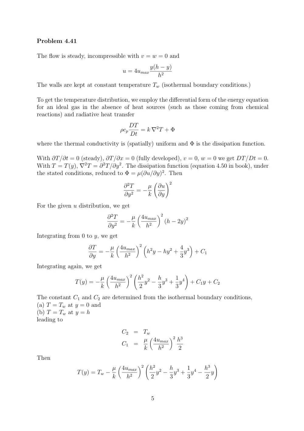
Problem 4.41
The flow is steady, incompressible with v = w = 0 and
u = 4umax
y(h − y)
h2
The walls are kept at constant temperature Tw (isothermal boundary conditions.)
To get the temperature distribution, we employ the differential form of the energy equation
for an ideal gas in the absence of heat sources (such as those coming from chemical
reactions) and radiative heat transfer
ρcp
DT
Dt = k ∇2T + Φ
where the thermal conductivity is (spatially) uniform and Φ is the dissipation function.
With ∂T/∂t = 0 (steady), ∂T/∂x = 0 (fully developed), v = 0, w = 0 we get DT/Dt = 0.
With T = T(y), ∇2T = ∂2T/∂y2. The dissipation function (equation 4.50 in book), under
the stated conditions, reduced to Φ = µ(∂u/∂y)2. Then
∂2T
∂y2 = −µ
k
�∂u
∂y
�2
For the given u distribution, we get
∂2T
∂y2 = −µ
k
�4umax
h2
�2
(h − 2y)2
Integrating from 0 to y, we get
∂T
∂y = −µ
k
�4umax
h2
�2 �
h2y − hy2 + 4
3y3
�
+ C1
Integrating again, we get
T(y) = −µ
k
�4umax
h2
�2 �h2
2 y2 − h
3y3 + 1
3y4
�
+ C1y + C2
The constant C1 and C2 are determined from the isothermal boundary conditions,
(a) T = Tw at y = 0 and
(b) T = Tw at y = h
leading to
C2
=
Tw
C1
=
µ
k
�4umax
h2
�2 h3
2
Then
T(y) = Tw − µ
k
�4umax
h2
�2 �h2
2 y2 − h
3y3 + 1
3y4 − h3
2 y
�
5
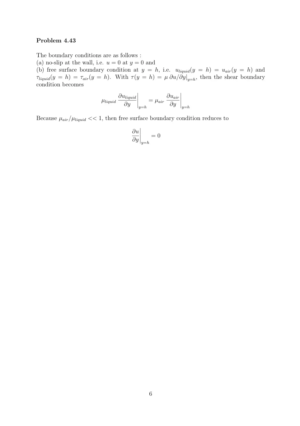
Problem 4.43
The boundary conditions are as follows :
(a) no-slip at the wall, i.e. u = 0 at y = 0 and
(b) free surface boundary condition at y = h, i.e.
uliquid(y = h) = uair(y = h) and
τliquid(y = h) = τair(y = h). With τ(y = h) = µ ∂u/∂y|y=h, then the shear boundary
condition becomes
µliquid
∂uliquid
∂y
�����
y=h
= µair
∂uair
∂y
�����
y=h
Because µair/µliquid << 1, then free surface boundary condition reduces to
∂u
∂y
�����
y=h
= 0
6
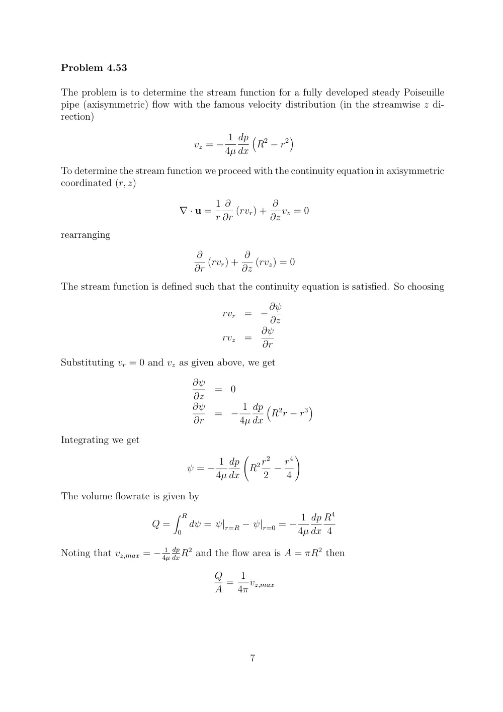
Problem 4.53
The problem is to determine the stream function for a fully developed steady Poiseuille
pipe (axisymmetric) flow with the famous velocity distribution (in the streamwise z di-
rection)
vz = − 1
4µ
dp
dx
�
R2 − r2�
To determine the stream function we proceed with the continuity equation in axisymmetric
coordinated (r, z)
∇ · u = 1
r
∂
∂r (rvr) + ∂
∂zvz = 0
rearranging
∂
∂r (rvr) + ∂
∂z (rvz) = 0
The stream function is defined such that the continuity equation is satisfied. So choosing
rvr
=
−∂ψ
∂z
rvz
=
∂ψ
∂r
Substituting vr = 0 and vz as given above, we get
∂ψ
∂z
=
0
∂ψ
∂r
=
− 1
4µ
dp
dx
�
R2r − r3�
Integrating we get
ψ = − 1
4µ
dp
dx
�
R2r2
2 − r4
4
�
The volume flowrate is given by
Q =
� R
0 dψ = ψ|r=R − ψ|r=0 = − 1
4µ
dp
dx
R4
4
Noting that vz,max = − 1
4µ
dp
dxR2 and the flow area is A = πR2 then
Q
A = 1
4πvz,max
7
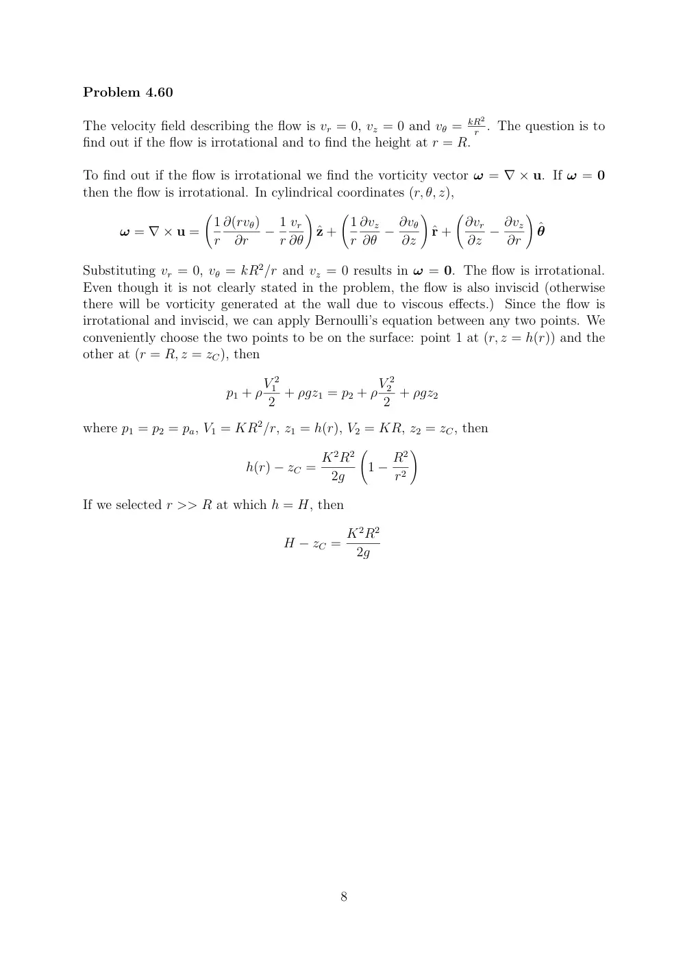
Problem 4.60
The velocity field describing the flow is vr = 0, vz = 0 and vθ = kR2
r . The question is to
find out if the flow is irrotational and to find the height at r = R.
To find out if the flow is irrotational we find the vorticity vector ω = ∇ × u. If ω = 0
then the flow is irrotational. In cylindrical coordinates (r, θ, z),
ω = ∇ × u =
�1
r
∂(rvθ)
∂r
− 1
r
vr
∂θ
�
ˆz +
�1
r
∂vz
∂θ − ∂vθ
∂z
�
ˆr +
�∂vr
∂z − ∂vz
∂r
�
ˆθ
Substituting vr = 0, vθ = kR2/r and vz = 0 results in ω = 0. The flow is irrotational.
Even though it is not clearly stated in the problem, the flow is also inviscid (otherwise
there will be vorticity generated at the wall due to viscous effects.) Since the flow is
irrotational and inviscid, we can apply Bernoulli’s equation between any two points. We
conveniently choose the two points to be on the surface: point 1 at (r, z = h(r)) and the
other at (r = R, z = zC), then
p1 + ρV 2
1
2 + ρgz1 = p2 + ρV 2
2
2 + ρgz2
where p1 = p2 = pa, V1 = KR2/r, z1 = h(r), V2 = KR, z2 = zC, then
h(r) − zC = K2R2
2g
�
1 − R2
r2
�
If we selected r >> R at which h = H, then
H − zC = K2R2
2g
8
Problem 4.83
This is a taste of classical lubrication theory.
The gap h is very small compared to
characteristic dimension in the flow direction, h << L. Furthermore, the flow is inertia
free Du/Dt ≃ 0. This is because the flow is (i) steady, (ii) 2D with w = 0, (iii) from order
of magnitude analysis of the continuity equation v ∼ u(h/L) ⇒ v << u (since h << L).
Careful analysis of the x and y components1 of the momentum equation yields
0
≃
−∂p
∂x + µ∂2u
∂y2
0
≃
−∂p
∂y
The second equation results in p = p(x) so that the first equation becomes
∂2u
∂y2 = 1
µ
dp
dx
Integrating
u(y) = 1
2µ
dp
dxy2 + C1y + C2
where the constants C1 and C2 are determined using the boundary conditions
(a) u = U at y = 0 and
(b) u = 0 at y = h,
resulting in
C2
=
U
C1
=
− 1
2µ
dp
dxh − U
h
The velocity profile is then given by
u(y) = 1
2µ
dp
dx(y2 − hy) + U
�
1 − y
h
�
1Since the flow is 2D in x and y, the z component of the momentum equation is irrelevant.
9