
MECH 314 Problems 2, Spring 2014
American University of Beirut · Introduction to Fluids Engineering · 10 pages

More MECH 314 files
Show the text of this problems
MECH 660 Advanced Fluid Mechanics
March 17, 2004
American University of Beirut, Spring 2005
Handout # PS4 Solution
Problem Set 4 Solution: Viscous Flow
“Advanced Fluid Mechanics Problems” by Shapiro and Sonin
Problems 6.1, 6.3, 6.7, 6.10, 6.16, 6.20, 6.21.
Problem 6.1
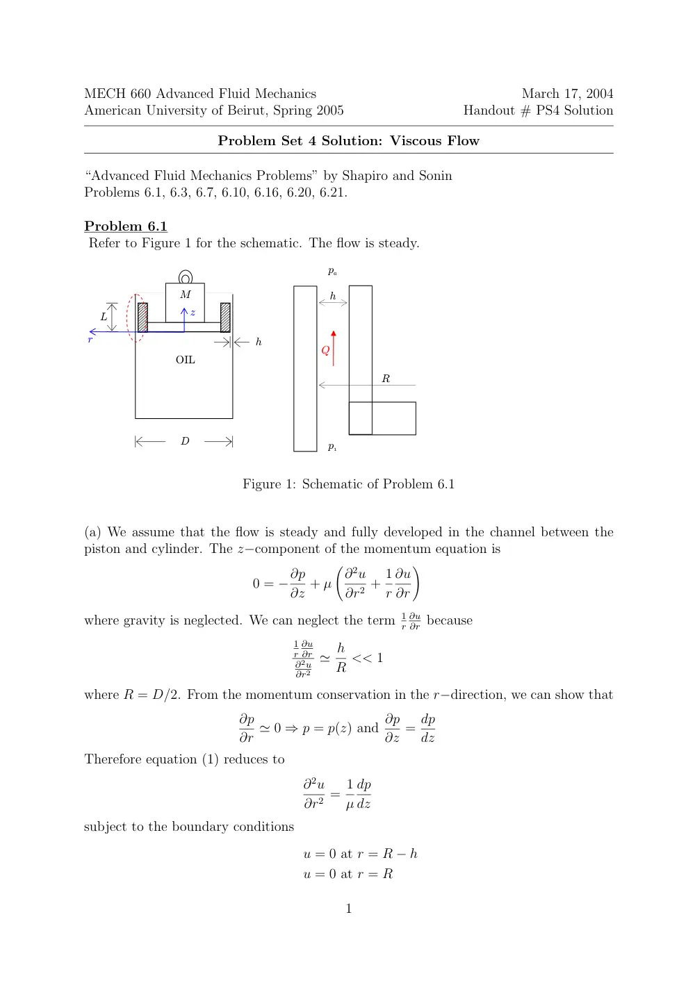
Refer to Figure 1 for the schematic. The flow is steady.
M
OIL
L
h
D
p1
pa
h
Q
R
z
r
Figure 1: Schematic of Problem 6.1
(a) We assume that the flow is steady and fully developed in the channel between the
piston and cylinder. The z−component of the momentum equation is
0 = −∂p
∂z + µ
�∂2u
∂r2 + 1
r
∂u
∂r
�
where gravity is neglected. We can neglect the term 1
r
∂u
∂r because
1
r
∂u
∂r
∂2u
∂r2
≃ h
R << 1
where R = D/2. From the momentum conservation in the r−direction, we can show that
∂p
∂r ≃ 0 ⇒ p = p(z) and ∂p
∂z = dp
dz
Therefore equation (1) reduces to
∂2u
∂r2 = 1
µ
dp
dz
subject to the boundary conditions
u = 0 at r = R − h
u = 0 at r = R
1
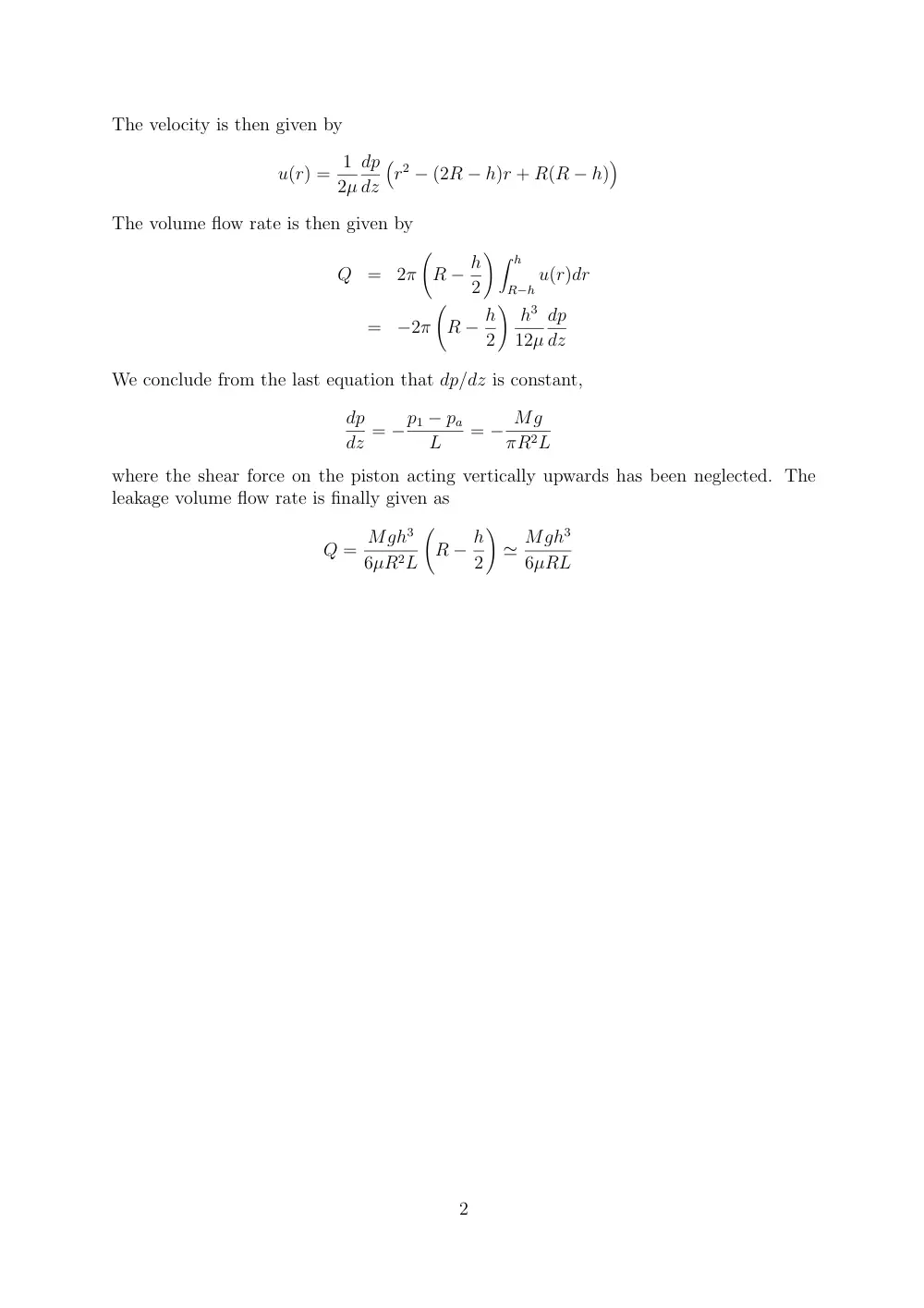
The velocity is then given by
u(r) = 1
2µ
dp
dz
�
r2 − (2R − h)r + R(R − h)
�
The volume flow rate is then given by
Q
=
2π
�
R − h
2
� � h
R−h u(r)dr
=
−2π
�
R − h
2
� h3
12µ
dp
dz
We conclude from the last equation that dp/dz is constant,
dp
dz = −p1 − pa
L
= − Mg
πR2L
where the shear force on the piston acting vertically upwards has been neglected. The
leakage volume flow rate is finally given as
Q = Mgh3
6µR2L
�
R − h
2
�
≃ Mgh3
6µRL
2
Problem 6.3
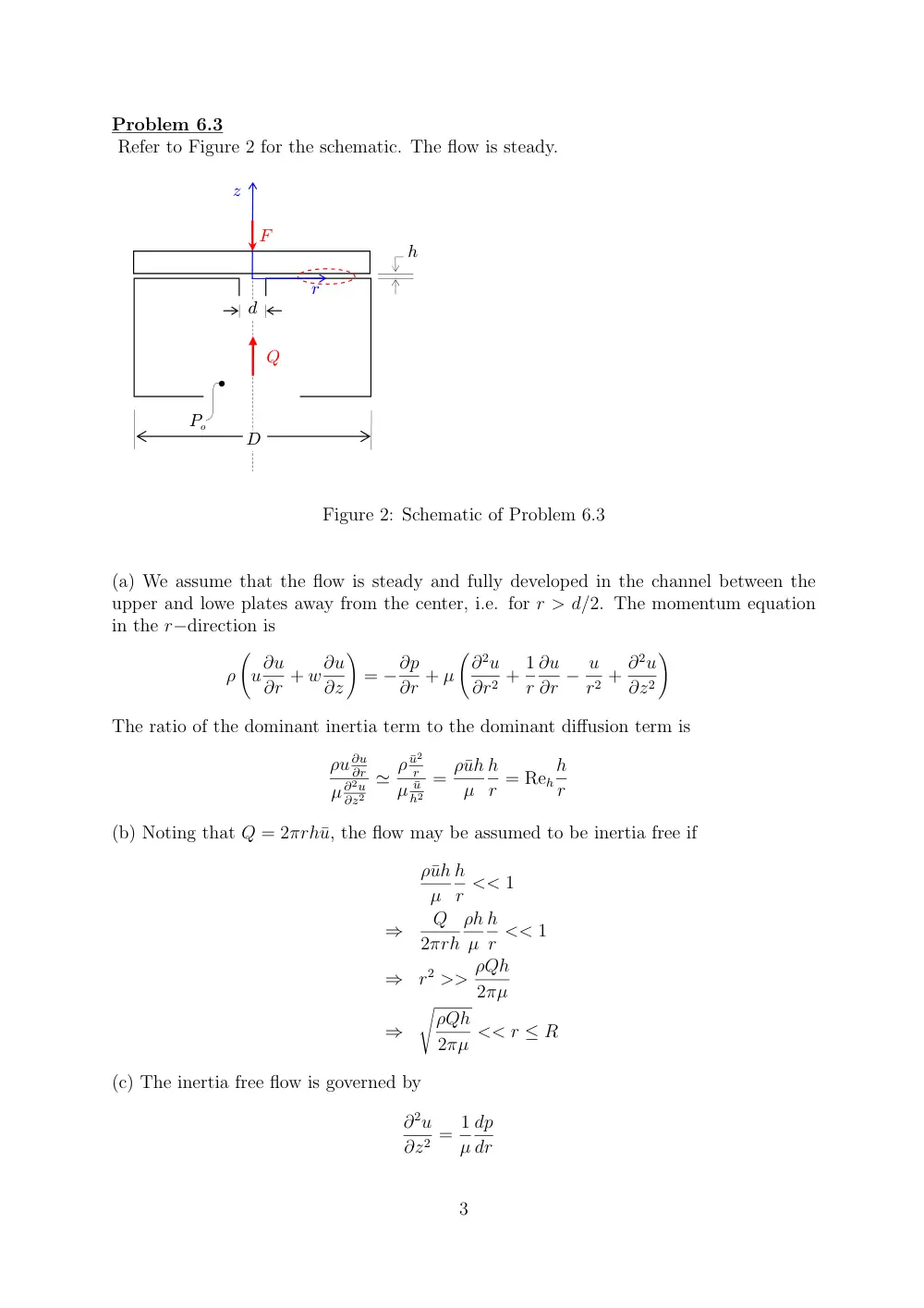
Refer to Figure 2 for the schematic. The flow is steady.
Po
Q
D
F
h
d
r
z
Figure 2: Schematic of Problem 6.3
(a) We assume that the flow is steady and fully developed in the channel between the
upper and lowe plates away from the center, i.e. for r > d/2. The momentum equation
in the r−direction is
ρ
�
u∂u
∂r + w∂u
∂z
�
= −∂p
∂r + µ
�∂2u
∂r2 + 1
r
∂u
∂r − u
r2 + ∂2u
∂z2
�
The ratio of the dominant inertia term to the dominant diffusion term is
ρu ∂u
∂r
µ ∂2u
∂z2
≃ ρ ¯u2
r
µ ¯u
h2
= ρ¯uh
µ
h
r = Reh
h
r
(b) Noting that Q = 2πrh¯u, the flow may be assumed to be inertia free if
ρ¯uh
µ
h
r << 1
⇒
Q
2πrh
ρh
µ
h
r << 1
⇒
r2 >> ρQh
2πµ
⇒
�
ρQh
2πµ << r ≤ R
(c) The inertia free flow is governed by
∂2u
∂z2 = 1
µ
dp
dr
3
subject to the boundary conditions
u = 0 at z = 0
u = 0 at z = h
The velocity is then given by
u = 1
2µ
dp
dr
�
z2 − zh
�
The volume flow rate is
Q
=
2πr
2µ
dp
dr
� h
0
�
z2 − zh
�
dz
=
−πrh3
6µ
dp
dr
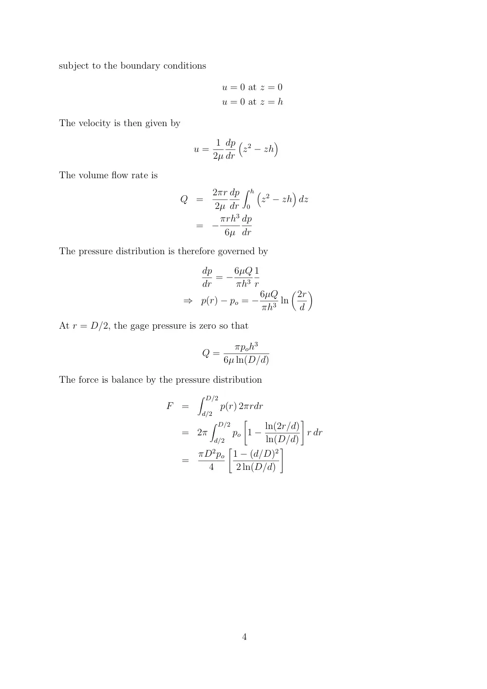
The pressure distribution is therefore governed by
dp
dr = −6µQ
πh3
1
r
⇒
p(r) − po = −6µQ
πh3 ln
�2r
d
�
At r = D/2, the gage pressure is zero so that
Q =
πpoh3
6µ ln(D/d)
The force is balance by the pressure distribution
F
=
� D/2
d/2
p(r) 2πrdr
=
2π
� D/2
d/2
po
�
1 − ln(2r/d)
ln(D/d)
�
r dr
=
πD2po
4
�1 − (d/D)2
2 ln(D/d)
�
4
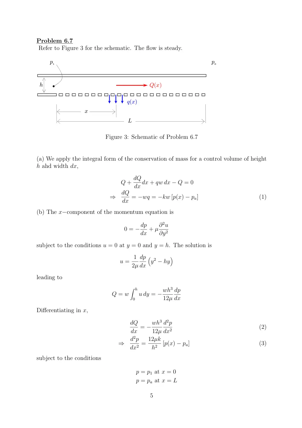
Problem 6.7
Refer to Figure 3 for the schematic. The flow is steady.
h
pa
p1
Q(x)
q(x)
x
L
Figure 3: Schematic of Problem 6.7
(a) We apply the integral form of the conservation of mass for a control volume of height
h ahd width dx,
Q + dQ
dx dx + qw dx − Q = 0
⇒
dQ
dx = −wq = −kw [p(x) − pa]
(1)
(b) The x−component of the momentum equation is
0 = −dp
dx + µ∂2u
∂y2
subject to the conditions u = 0 at y = 0 and y = h. The solution is
u = 1
2µ
dp
dx
�
y2 − hy
�
leading to
Q = w
� h
0 u dy = −wh3
12µ
dp
dx
Differentiating in x,
dQ
dx = −wh3
12µ
d2p
dx2
(2)
⇒
d2p
dx2 = 12µk
h2
[p(x) − pa]
(3)
subject to the conditions
p = p1 at x = 0
p = pa at x = L
5
(c) In this case we have a conventional Poiseuille flow. If q is very small, then k is very
small. From equation (3)
d2p
dx2 ≃ 0
⇒
dp
dx = pa − p1
L
Therefore the location at which the gage pressure reaches half the inlet gage pressure is
x∗ = L/2.
(d) In this case Q(x = L) ≃ 0. A first order approximation in this xase is to assume that
Q varies linearly from Q = Q0 at x = 0 to Q = 0 at x = L,
dQ
dx ≃ −Q0
L
⇒
Q ≃ Q0
�
1 − x
L
�
From equation (2),
wh3
12µ
d2p
dx2 = Q0
L
Leading to the pressure distribution
p(x) = 6µQ0
wh3Lx2 +
�pa − p1
L
− 6µQ0
wh3
�
x + p1
(4)
To get Q0, we integrate equation (1),
0 − Q0 =
� L
0 −kw [p(x) − pa] dx
⇒
Q0 = kw
� L
0
� 6µQ0
wh3Lx2 +
�pa − p1
L
− 6µQ0
wh3
�
x + p1 − pa
�
dx
⇒
Q0 = wh3(p1 − pa)
2µL + 2h3/kL ≃ wh3(p1 − pa)
2µL
Note kL >> h3/µL in this case. Substituting Q0 in equation (4), we get
p(x) − pa
p1 − pa
= 3 x2
L2 − 4 x
L + 1
Now we find x∗ such that (p(x∗) − pa)/(p1 − pa) = 1
2, resulting in x∗ = 0.14L.
(e) The differential equation
d2p∗
dx2 = αp∗(x)
where p∗(x) = p(x)−pa
p1−pa and α = 12µk
h2
have the general solution
p∗(x) = C1ex√α + C2e−x√α
6
subject to the boundary conditions p∗ = 1 at x = 0 and p∗ = 0 at x = L, we get
C1 + C2 = 1
C1eL√α + C2e−L√α = 0
leading to
p(x) − pa
p1 − pa
= e(L−x)√α − e−(L−x)√α
eL√α − e−L√α
• case 1: in the limit k → 0, i.e. α = 0,
p(x) − pa
p1 − pa
= L − x
L
at x = L/2, we get p(x)−pa
p1−pa = 1/2.
• case 2: in the limit L√α >> 0, ,
p(x) − pa
p1 − pa
= e−x√α
at x = ln(2)
√α , we get p(x)−pa
p1−pa = 1/2.
7
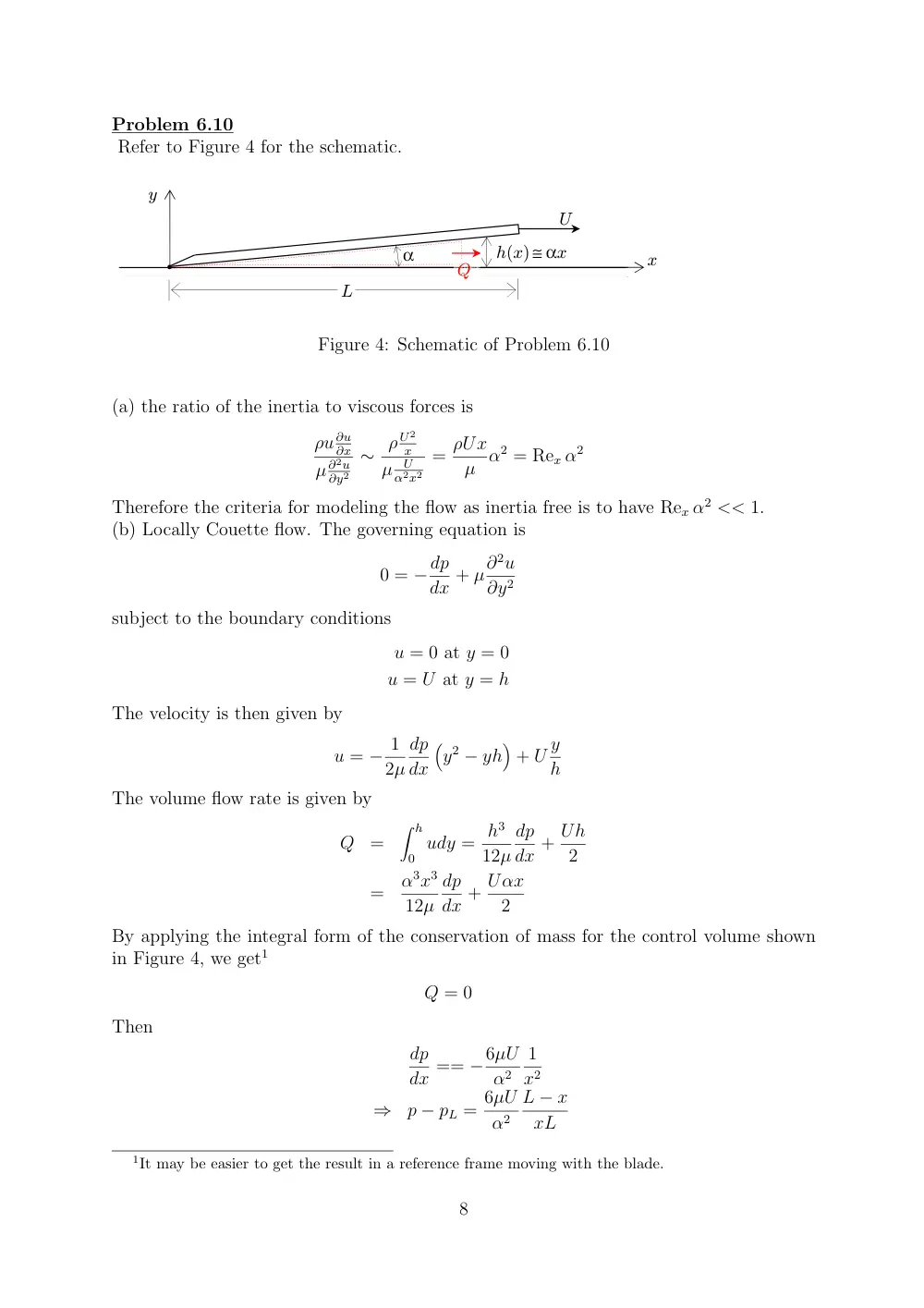
Problem 6.10
Refer to Figure 4 for the schematic.
α
y
x
U
h(x)≅ αx
L
Q
Figure 4: Schematic of Problem 6.10
(a) the ratio of the inertia to viscous forces is
ρu ∂u
∂x
µ ∂2u
∂y2
∼ ρ U2
x
µ
U
α2x2
= ρUx
µ α2 = Rex α2
Therefore the criteria for modeling the flow as inertia free is to have Rex α2 << 1.
(b) Locally Couette flow. The governing equation is
0 = −dp
dx + µ∂2u
∂y2
subject to the boundary conditions
u = 0 at y = 0
u = U at y = h
The velocity is then given by
u = − 1
2µ
dp
dx
�
y2 − yh
�
+ U y
h
The volume flow rate is given by
Q
=
� h
0 udy = h3
12µ
dp
dx + Uh
2
=
α3x3
12µ
dp
dx + Uαx
2
By applying the integral form of the conservation of mass for the control volume shown
in Figure 4, we get1
Q = 0
Then
dp
dx == −6µU
α2
1
x2
⇒
p − pL = 6µU
α2
L − x
xL
1It may be easier to get the result in a reference frame moving with the blade.
8
Problem 6.16
Refer to Figure 5 for the schematic.
viscous liquid
y
x
h(x,t)
θ
g
air, pa
dx
Figure 5: Schematic of Problem 6.16
(a) We apply conservation of mass for a control volume shown in the figure,
∂
∂t
�
CV ρ dV +
�
CS ρu · ˆn dS = 0
⇒
∂
∂t(ρh dx) + ρdQ
dx dx = 0
⇒
∂h
∂t + dQ
dx = 0
(5)
where Q is the volume flowrate. The differential form of the momentum conservation in
the x−direction is
0 = µ∂u2
∂y2 + ρg sin θ
where the pressure gradient is zero and the inertia term is neglected.
The boundary
conditions are
u = 0 at y = 0
τ = µ∂u
∂y = 0 at y = h
The velocity is then given by
u = ρg sin θ
µ
�
hy − y2
2
�
The volume flow rate is
Q =
� h
0 u dy = ρg sin θ
3µ
h3
⇒
dQ
dx = ρg sin θ
µ
h2dh
dx
9
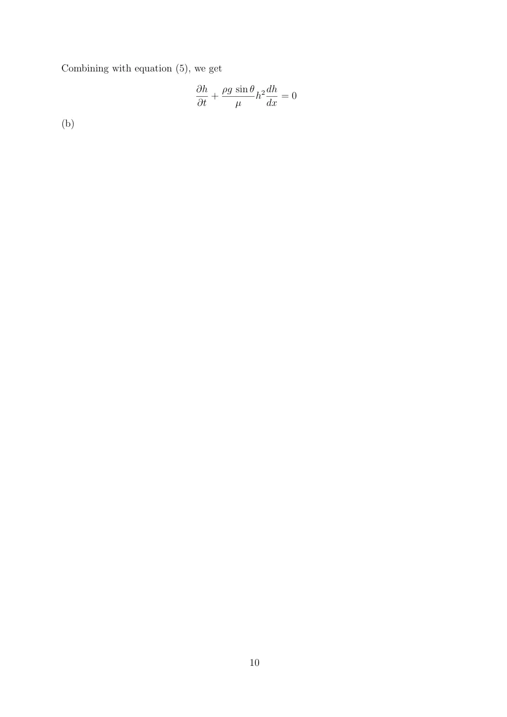
Combining with equation (5), we get
∂h
∂t + ρg sin θ
µ
h2dh
dx = 0
(b)
10