
MECH 314 Problems 6, Spring 2014
American University of Beirut · Introduction to Fluids Engineering · 6 pages

More MECH 314 files
Show the text of this problems
MECH 411 Introduction to Fluid Mechanics
November 18, 2004
American University of Beirut, Fall 2004-2005
Handout # PS3
Problem Set 3 Solution
Textbook:
Conservation of mass:
Problems 3.19, 3.23, 3.25, 3.29
Conservation of momentum:
Problems 3.39, 3.53, 3.80, 3.82
Conservation of energy:
Problems 3.132, 3.137, 3.143, 3.144
1
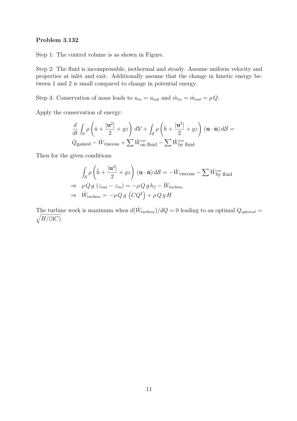
Problem 3.132
Step 1: The control volume is as shown in Figure.
Step 2: The fluid is incompressible, isothermal and steady. Assume uniform velocity and
properties at inlet and exit. Additionally assume that the change in kinetic energy be-
tween 1 and 2 is small compared to change in potential energy.
Step 3: Conservation of mass leads to uin = uout and ˙min = ˙mout = ρ Q.
Apply the conservation of energy:
d
dt
�
V ρ
�
ˆu + |u2|
2
+ gz
�
dV +
�
S ρ
�
ˆh + |u2|
2
+ gz
�
(u · ˆn) dS =
˙Qgained − ˙Wviscous +
� ˙W
ext
on fluid −
� ˙W
ext
by fluid
Then for the given conditions
�
S ρ
�
ˆh + |u2|
2
+ gz
�
(u · ˆn) dS = − ˙Wviscous −
� ˙W
ext
by fluid
⇒
ρ Q g (zout − zin) = −ρ Q g hf − ˙Wturbine
⇒
˙Wturbine = −ρ Q g
�
CQ2�
+ ρ Q g H
The turbine work is maximum when d( ˙Wturbine)/dQ = 0 leading to an optimal Qoptimal =
�
H/(3C).
11
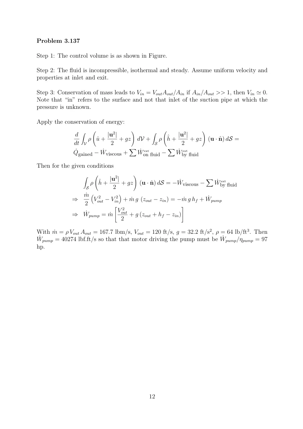
Problem 3.137
Step 1: The control volume is as shown in Figure.
Step 2: The fluid is incompressible, isothermal and steady. Assume uniform velocity and
properties at inlet and exit.
Step 3: Conservation of mass leads to Vin = VoutAout/Ain if Ain/Aout >> 1, then Vin ≃ 0.
Note that “in” refers to the surface and not that inlet of the suction pipe at which the
pressure is unknown.
Apply the conservation of energy:
d
dt
�
V ρ
�
ˆu + |u2|
2
+ gz
�
dV +
�
S ρ
�
ˆh + |u2|
2
+ gz
�
(u · ˆn) dS =
˙Qgained − ˙Wviscous +
� ˙W
ext
on fluid −
� ˙W
ext
by fluid
Then for the given conditions
�
S ρ
�
ˆh + |u2|
2
+ gz
�
(u · ˆn) dS = − ˙Wviscous −
� ˙W
ext
by fluid
⇒
˙m
2
�
V 2
out − V 2
in
�
+ ˙m g (zout − zin) = − ˙m g hf + ˙Wpump
⇒
˙Wpump = ˙m
�V 2
out
2
+ g (zout + hf − zin)
�
With ˙m = ρ Vout Aout = 167.7 lbm/s, Vout = 120 ft/s, g = 32.2 ft/s2, ρ = 64 lb/ft3. Then
˙Wpump = 40274 lbf.ft/s so that that motor driving the pump must be ˙Wpump/ηpump = 97
hp.
12
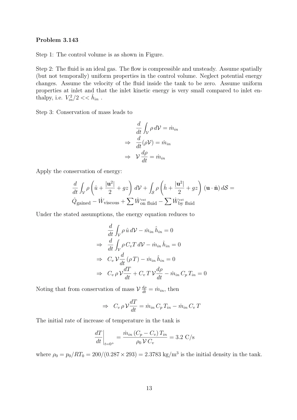
Problem 3.143
Step 1: The control volume is as shown in Figure.
Step 2: The fluid is an ideal gas. The flow is compressible and unsteady. Assume spatially
(but not temporally) uniform properties in the control volume. Neglect potential energy
changes. Assume the velocity of the fluid inside the tank to be zero. Assume uniform
properties at inlet and that the inlet kinetic energy is very small compared to inlet en-
thalpy, i.e. V 2
in/2 << ˆhin .
Step 3: Conservation of mass leads to
d
dt
�
V ρ dV = ˙min
⇒
d
dt(ρV) = ˙min
⇒
V dρ
dt = ˙min
Apply the conservation of energy:
d
dt
�
V ρ
�
ˆu + |u2|
2
+ gz
�
dV +
�
S ρ
�
ˆh + |u2|
2
+ gz
�
(u · ˆn) dS =
˙Qgained − ˙Wviscous +
� ˙W
ext
on fluid −
� ˙W
ext
by fluid
Under the stated assumptions, the energy equation reduces to
d
dt
�
V ρ ˆu dV − ˙min ˆhin = 0
⇒
d
dt
�
V ρ CvT dV − ˙min ˆhin = 0
⇒
Cv V d
dt (ρ T) − ˙min ˆhin = 0
⇒
Cv ρ V dT
dt + Cv T V dρ
dt − ˙min Cp Tin = 0
Noting that from conservation of mass V dρ
dt = ˙min, then
⇒
Cv ρ V dT
dt = ˙min Cp Tin − ˙min Cv T
The initial rate of increase of temperature in the tank is
dT
dt
�����
t=0+
= ˙min (Cp − Cv) Tin
ρ0 V Cv
= 3.2 C/s
where ρ0 = p0/RT0 = 200/(0.287×293) = 2.3783 kg/m3 is the initial density in the tank.
13
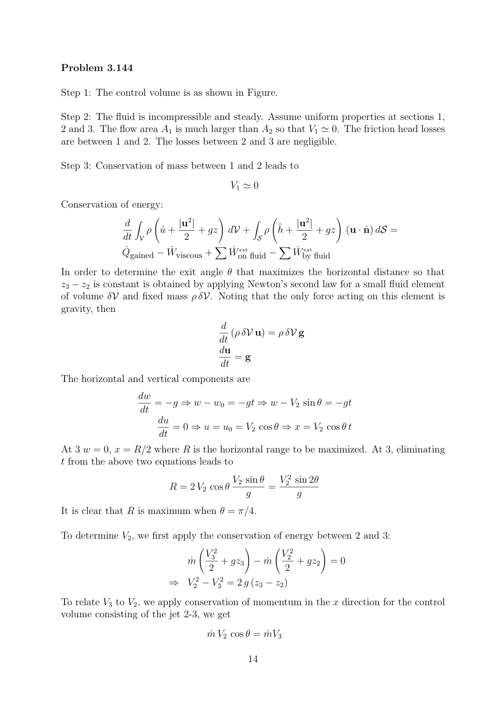
Problem 3.144
Step 1: The control volume is as shown in Figure.
Step 2: The fluid is incompressible and steady. Assume uniform properties at sections 1,
2 and 3. The flow area A1 is much larger than A2 so that V1 ≃ 0. The friction head losses
are between 1 and 2. The losses between 2 and 3 are negligible.
Step 3: Conservation of mass between 1 and 2 leads to
V1 ≃ 0
Conservation of energy:
d
dt
�
V ρ
�
ˆu + |u2|
2
+ gz
�
dV +
�
S ρ
�
ˆh + |u2|
2
+ gz
�
(u · ˆn) dS =
˙Qgained − ˙Wviscous +
� ˙W
ext
on fluid −
� ˙W
ext
by fluid
In order to determine the exit angle θ that maximizes the horizontal distance so that
z3 − z2 is constant is obtained by applying Newton’s second law for a small fluid element
of volume δV and fixed mass ρ δV. Noting that the only force acting on this element is
gravity, then
d
dt (ρ δV u) = ρ δV g
du
dt = g
The horizontal and vertical components are
dw
dt = −g ⇒ w − w0 = −gt ⇒ w − V2 sin θ = −gt
du
dt = 0 ⇒ u = u0 = V2 cos θ ⇒ x = V2 cos θ t
At 3 w = 0, x = R/2 where R is the horizontal range to be maximized. At 3, eliminating
t from the above two equations leads to
R = 2 V2 cos θ V2 sin θ
g
= V 2
2 sin 2θ
g
It is clear that R is maximum when θ = π/4.
To determine V2, we first apply the conservation of energy between 2 and 3:
˙m
�V 2
3
2 + gz3
�
− ˙m
�V 2
2
2 + gz2
�
= 0
⇒
V 2
2 − V 2
3 = 2 g (z3 − z2)
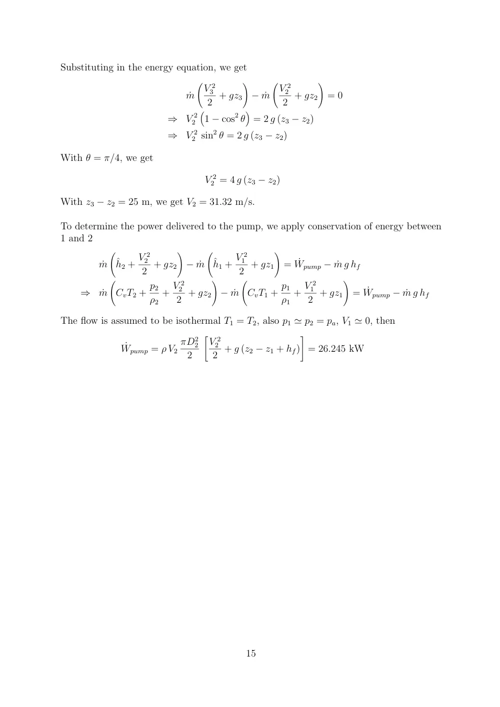
To relate V3 to V2, we apply conservation of momentum in the x direction for the control
volume consisting of the jet 2-3, we get
˙m V2 cos θ = ˙mV3
14
Substituting in the energy equation, we get
˙m
�V 2
3
2 + gz3
�
− ˙m
�V 2
2
2 + gz2
�
= 0
⇒
V 2
2
�
1 − cos2 θ
�
= 2 g (z3 − z2)
⇒
V 2
2 sin2 θ = 2 g (z3 − z2)
With θ = π/4, we get
V 2
2 = 4 g (z3 − z2)
With z3 − z2 = 25 m, we get V2 = 31.32 m/s.
To determine the power delivered to the pump, we apply conservation of energy between
1 and 2
˙m
�
ˆh2 + V 2
2
2 + gz2
�
− ˙m
�
ˆh1 + V 2
1
2 + gz1
�
= ˙Wpump − ˙m g hf
⇒
˙m
�
CvT2 + p2
ρ2
+ V 2
2
2 + gz2
�
− ˙m
�
CvT1 + p1
ρ1
+ V 2
1
2 + gz1
�
= ˙Wpump − ˙m g hf
The flow is assumed to be isothermal T1 = T2, also p1 ≃ p2 = pa, V1 ≃ 0, then
˙Wpump = ρ V2
πD2
2
2
�V 2
2
2 + g (z2 − z1 + hf)
�
= 26.245 kW
15