
MECH 314 Problems 4, Spring 2014
American University of Beirut · Introduction to Fluids Engineering · 5 pages


More MECH 314 files
Show the text of this problems
MECH 411 Introduction to Fluid Mechanics
October 30, 2004
American University of Beirut, Fall 2004-2005
Handout # PS2
Selected Problems from Problem Set 2
Problem 2.97
B
A
R
θ
x
y
y = R sin θ
dFFFF=-p rrrr dS
ˆ
r =
r =
r =
r = cos θ xxxx + sin θ yyyy
ˆ
ˆ
ˆ
dS = R dθ
rrrrˆ
θ0
B
A
R
θ
x
y
y = R sin θ
dFFFF=-p rrrr dS
ˆ
dFFFF=-p rrrr dS
ˆ
r =
r =
r =
r = cos θ xxxx + sin θ yyyy
ˆ
ˆ
ˆ
dS = R dθ
rrrrˆrrrrˆ
θ0
The gauge pressure at y is
pg(y) = p(y) − pa = ρ g (H − y) = ρ g (H − R sin θ)
(1)
The unit outward normal vector is
ˆn = ˆr = cos θ ˆx + sin θ ˆy
(2)
The force due to pressure distribution is
F
=
�
dF =
�
S −pg(y) ˆn dS
=
�
dF = −WR
� π
π/4 ρ g (H − R sin θ) (cos θ ˆx + sin θ ˆy) dθ
=
−ρgWR
�R
4 − H
√
2
�
ˆx + ρgWR
�
R
�3π
8 + 1
4
�
− H
�
1 + 1
√
2
��
ˆy
(3)
Noting that the position vector on the gate is r = x ˆx + y ˆy = R(cos θ ˆx + sin θ ˆy), the
moment about the center of coordinates is
MO =
�
r × dF = R∗ × F
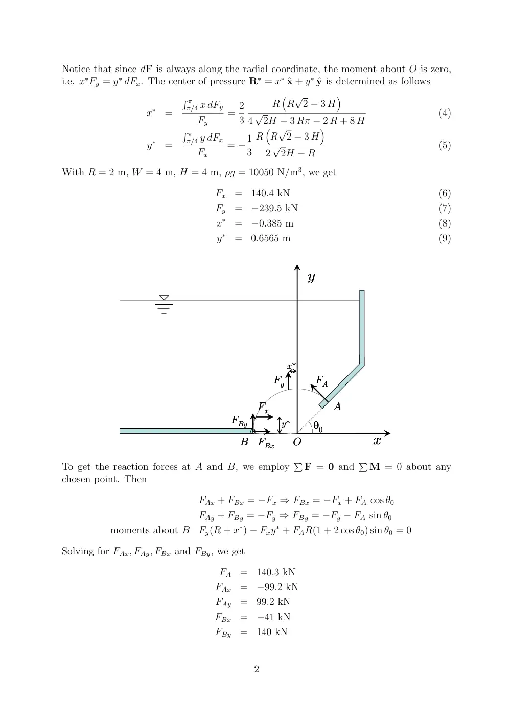
where R∗ = x∗ ˆx + y∗ ˆy is the center of pressure. Then satisfying the x and y components
of the above equation yields
�
−x dFy
=
−x∗Fy
�
y dFx
=
y∗Fx
1
Notice that since dF is always along the radial coordinate, the moment about O is zero,
i.e. x∗Fy = y∗ dFx. The center of pressure R∗ = x∗ ˆx + y∗ ˆy is determined as follows
x∗
=
� π
π/4 x dFy
Fy
= 2
3
R
�
R
√
2 − 3 H
�
4
√
2H − 3 Rπ − 2 R + 8 H
(4)
y∗
=
� π
π/4 y dFx
Fx
= −1
3
R
�
R
√
2 − 3 H
�
2
√
2H − R
(5)
With R = 2 m, W = 4 m, H = 4 m, ρg = 10050 N/m3, we get
Fx
=
140.4 kN
(6)
Fy
=
−239.5 kN
(7)
x∗
=
−0.385 m
(8)
y∗
=
0.6565 m
(9)
x
y
B
FBx
FBy
A
FA
Fx
Fy
x*
y*
O
θ0
x
y
B
FBx
FBy
A
FA
Fx
Fy
x*
y*
O
θ0
To get the reaction forces at A and B, we employ
� F = 0 and
� M = 0 about any
chosen point. Then
FAx + FBx = −Fx ⇒ FBx = −Fx + FA cos θ0
FAy + FBy = −Fy ⇒ FBy = −Fy − FA sin θ0
moments about B
Fy(R + x∗) − Fxy∗ + FAR(1 + 2 cos θ0) sin θ0 = 0
Solving for FAx, FAy, FBx and FBy, we get
FA
=
140.3 kN
FAx
=
−99.2 kN
FAy
=
99.2 kN
FBx
=
−41 kN
FBy
=
140 kN
2
Problem 2.119
mg
γ
�
�
�
� V
Wθ
F
�
�
F
�
�
θ
W
W/3
mg
γ
�
�
�
� V
Wθ
F
�
�
F
�
�
θ
W
W/3
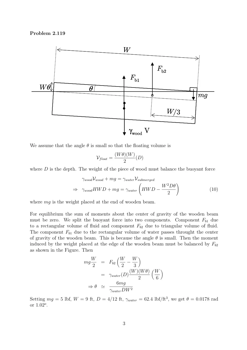
We assume that the angle θ is small so that the floating volume is
Vfloat = (Wθ)(W)
2
(D)
where D is the depth. The weight of the piece of wood must balance the buoyant force
γwoodVwood + mg = γwaterVsubmerged
⇒
γwoodHWD + mg = γwater
�
HWD − W 2Dθ
2
�
(10)
where mg is the weight placed at the end of wooden beam.
For equilibrium the sum of moments about the center of gravity of the wooden beam
must be zero. We split the buoyant force into two components. Component Fb1 due
to a rectangular volume of fluid and component Fb2 due to triangular volume of fluid.
The component Fb1 due to the rectangular volume of water passes throught the center
of gravity of the wooden beam. This is because the angle θ is small. Then the moment
induced by the weight placed at the edge of the wooden beam must be balanced by Fb2
as shown in the Figure. Then
mgW
2
=
Fb2
�W
2 − W
3
�
=
γwater(D)(W)(Wθ)
2
�W
6
�
⇒ θ
≃
6mg
γwaterDW 2
Setting mg = 5 lbf, W = 9 ft, D = 4/12 ft, γwater = 62.4 lbf/ft3, we get θ = 0.0178 rad
or 1.02o.
3
Substituting in equation (10), we get γwood = 42.4 lbf/ft3. The specific gravity of wood is
then SG ≃ γwood/γwater = 0.68.
4
Problem 2.147
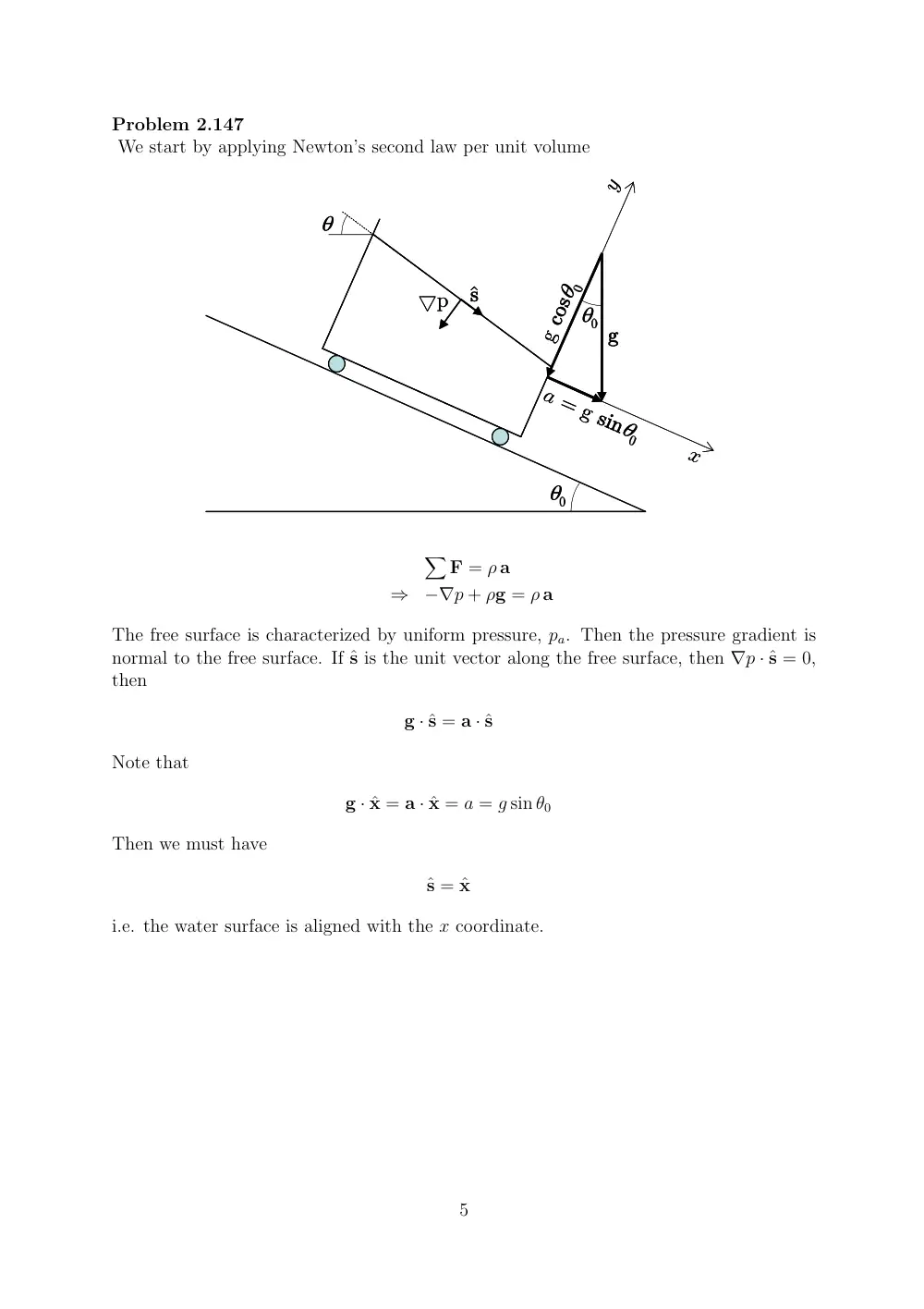
We start by applying Newton’s second law per unit volume
a = g sinθ
�
θ
θ
�
θ
�
g
g cosθ
�
▽p
sˆ
x
y
a = g sinθ
�
θ
θ
�
θ
�
g
g cosθ
�
▽p
sˆ
x
y
�
F = ρ a
⇒
−∇p + ρg = ρ a
The free surface is characterized by uniform pressure, pa. Then the pressure gradient is
normal to the free surface. If ˆs is the unit vector along the free surface, then ∇p · ˆs = 0,
then
g · ˆs = a · ˆs
Note that
g · ˆx = a · ˆx = a = g sin θ0
Then we must have
ˆs = ˆx
i.e. the water surface is aligned with the x coordinate.
5