
PHY 201 Chapter 24, Fall 2017
Lebanese American University · Electricit and Magnetism · 51 pages · Dr. Jimmy Romanos





Showing the first 10 of 51 pages. Download the PDF to see all of it.
More PHY 201 files
Show the text of this chapter
CHAPTER 24
Electric Potential
Electric Potential
24-1
24-1 Electric Potential
PHY 201
If we release particle 1 at P, it begins to move and thus has kinetic energy.
Energy cannot appear by magic, so from where does it come?
It comes from the electric potential energy U associated with
the force between the two particles
To account for the potential energy U (which is a scalar quantity), we define an electric
potential V (also a scalar quantity) that is set up at P by particle 2.
The electric potential exists regardless of whether particle 1 is at P.
PHY 305
By analogy to the gravitational potential energy, we have for the electric
potential energy a 1/r relationship.
Where the zero of potential energy is at very large separation r (r >>1)
Potential energy can be positive or negative. It is positive for two like
charges and negative or two unlike charges.
PHY 201
24-1 Electric Potential
PHY 305
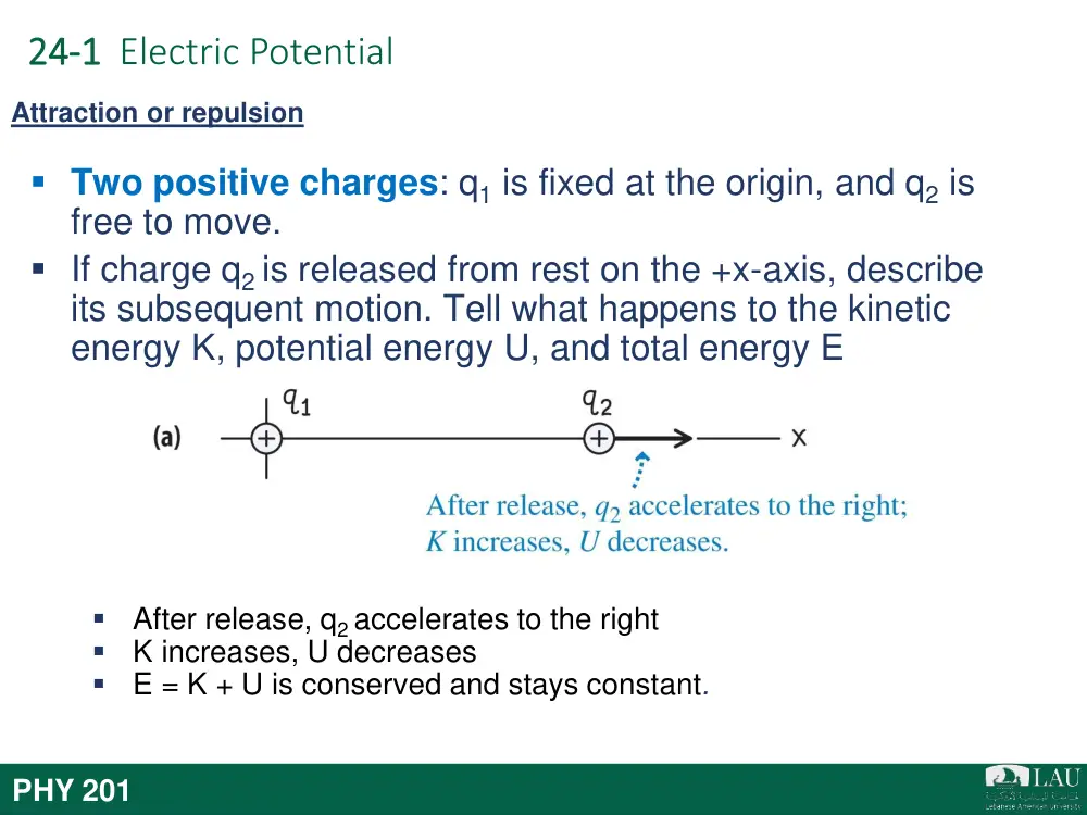
Two positive charges: q1 is fixed at the origin, and q2 is
free to move.
If charge q2 is released from rest on the +x-axis, describe
its subsequent motion. Tell what happens to the kinetic
energy K, potential energy U, and total energy E
Attraction or repulsion
After release, q2 accelerates to the right
K increases, U decreases
E = K + U is conserved and stays constant.
PHY 201
24-1 Electric Potential
PHY 305
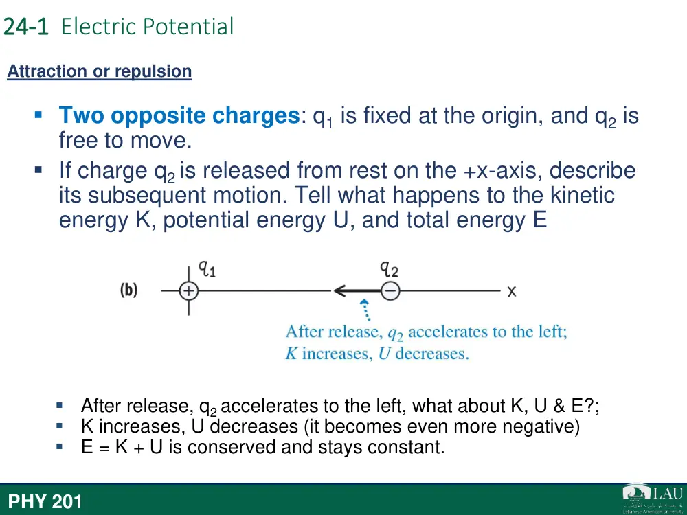
Two opposite charges: q1 is fixed at the origin, and q2 is
free to move.
If charge q2 is released from rest on the +x-axis, describe
its subsequent motion. Tell what happens to the kinetic
energy K, potential energy U, and total energy E
Attraction or repulsion
After release, q2 accelerates to the left, what about K, U & E?;
K increases, U decreases (it becomes even more negative)
E = K + U is conserved and stays constant.
PHY 201
24-1 Electric Potential
24-1 Electric Potential
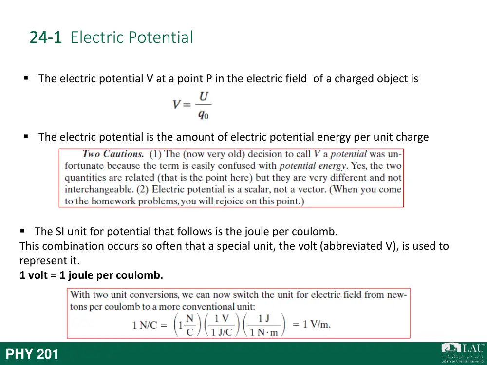
The electric potential V at a point P in the electric field of a charged object is
The electric potential is the amount of electric potential energy per unit charge
PHY 201
The SI unit for potential that follows is the joule per coulomb.
This combination occurs so often that a special unit, the volt (abbreviated V), is used to
represent it.
1 volt = 1 joule per coulomb.
24-1 Electric Potential
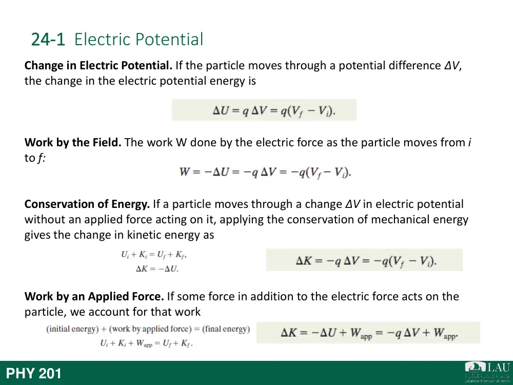
Change in Electric Potential. If the particle moves through a potential difference ΔV,
the change in the electric potential energy is
Work by the Field. The work W done by the electric force as the particle moves from i
to f:
Conservation of Energy. If a particle moves through a change ΔV in electric potential
without an applied force acting on it, applying the conservation of mechanical energy
gives the change in kinetic energy as
Work by an Applied Force. If some force in addition to the electric force acts on the
particle, we account for that work
PHY 201
24-1 Electric Potential
PHY 201
Definition: The electric potential, V, is the potential energy per unit
charge.
Thus, the electric potential a distance r for a point charge q is:
24-1 Electric Potential
PHY 201
Equipotential Surfaces and
the Electric Field
24-2
24-2 Equipotential Surfaces and the Electric Field
Adjacent points that have the same electric potential form an equipotential surface,
which can be either an imaginary surface or a real, physical surface.
Figure shows a family of equipotential
surfaces associated with the electric field
due to some distribution of charges. The
work done by the electric field on a
charged particle as the particle moves
from one end to the other of paths I and
II is zero because each of these paths
begins and ends on the same
equipotential surface and thus there is no
net change in potential. The work done
as the
charged particle moves from one end to the other of paths III and IV is not
zero but has the same value for both these paths because the initial and final potentials are
identical for the two paths; that is, paths III and IV connect the same pair of equipotential
surfaces.
PHY 201
24-2 Equipotential Surfaces and the Electric Field
PHY 201
24-2 Equipotential Surfaces and the Electric Field
The electric potential difference between two points i and f
is
where the integral is taken over any path connecting the
points. If the integration is difficult along any particular path,
we can choose a different path along which the integration
might be easier.
If we choose Vi = 0, we have, for the potential at a particular
point,
In a uniform field of magnitude E, the change in
potential from a higher equipotential surface to a
lower one, separated by distance Δx, is
A test charge q0 moves from point
i to point f along the path shown
in a non-uniform electric field.
During a displacement ds, an
electric force q0 E acts on the test
charge. This force points in the
direction of the field line at the
location of the test charge.
PHY 201
Potential due to a Charged
Particles
24-3
24-3 Potential due to a Charged Particle
The potential due to a collection of charged particles is
Thus, the potential is the algebraic sum of the individual potentials, with no
consideration of directions.
Potential due to a group of Charged Particles
PHY 201
Potential due to a Electric
Dipole
24-4
24-4 Potential due to a Electric Dipole
(a) Point P is a distance r from the midpoint O
of a dipole. The line OP makes an angle θ
with the dipole axis.
(b) If P is far from the dipole, the lines of
lengths r(+) and r(-) are approximately
parallel to the line of length r, and the
dashed black line is approximately
perpendicular to the line of length r(-).
The net potential at P is given by
We can approximate the two lines to P as being
parallel and their length difference as being the leg
of a right triangle with hypotenuse d (Fig. b). Also,
that difference is so small that the product of the
lengths is approximately r 2.
We can approximate V to be
where θ is measured from the dipole axis as
shown in Fig. a. And since p=qd, we have
PHY 201
Potential due to a
Continuous Charge
Distribution
24-5
24-5 Potential due to a Continuous Charge Distribution
For a continuous distribution of charge (over an extended object), the potential is found by
(1) dividing the distribution into charge elements dq that can be treated as particles and then
(2) summing the potential due to each element by integrating over the full distribution:
We now examine two continuous charge distributions, a line and a disk.
PHY 201
24-5 Potential due to a Continuous Charge Distribution
Line of Charge
Fig. a has a thin conducting rod of
length L. As shown in fig. b the
element of the rod has a differential
charge of
This element produces an electric
potential dV at point P (fig c) given by
We now find the total potential V produced by the rod at point P by integrating dV along
the length of the rod, from x = 0 to x = L (Figs.d and e)
Simplified to,
PHY 201
Calculating the Field from
the Potential
24-6
24-6 Calculating the Field from the Potential
PHY 201
Electric Potential Energy of a
System of Charged Particles
24-7
The electric potential energy of a system of charged
particles is equal to the work needed to assemble
the system with the particles initially at rest and
infinitely distant from each other. For two particles
at separation r,
Two charges held a fixed
distance r apart.
24-7 Electric Potential Energy of a System of Charged
Particles
Three charges are fixed at the
vertices of an equilateral triangle.
What is the electric potential
energy of the system?
PHY 201
PHY 305
Electric Potential Energy
Multiple charges
For 3 charges and more, each pair
will have a potential energy. The
total potential energy is the sum
over all three pairs.
The more charges there are the bigger the number of charge pairs (for
4 charges, there exist 6 pairs for 5 charges, 10 pairs, and so on…)
The bigger the computation above becomes.
It becomes necessary to describe energy in terms of the electric
potential.
PHY 201
Summary
24 Summary
Electric Potential
• The electric potential V at point P in
the electric field of a charged object:
Electric Potential Energy
• Electric potential energy U of the
particle-object system:
• If the particle moves through potential
ΔV:
Eq. 24-2
Eq. 24-3
Eq. 24-4
Mechanical Energy
• Applying the conservation of
mechanical energy gives the change in
kinetic energy:
• In case of an applied force in a particle
• In a special case when ΔK=0:
Eq. 24-9
Eq. 24-11
Eq. 24-12
Finding V from E
• The electric potential difference
between two point I and f is:
Eq. 24-18
PHY 201
24 Summary
Potential due to a Charged Particle
• due to a single charged particle at a
distance r from that particle :
• due to a collection of charged particles
Eq. 24-26
Eq. 24-27
Eq. 24-30
Potential due to a Continuous
Charge Distribution
• For a continuous distribution of
charge:
Eq. 24-32
Eq. 24-40
Calculating E from V
• The component of E in any direction is:
Eq. 24-46
Potential due to an Electric Dipole
• The electric potential of the dipole is
Electric Potential Energy of a System
of Charged Particle
• For two particles at separation r:
PHY 201
CHAPTER 25
Capacitance
Introduction
PHY 201
The capacitor: a device in which electrical energy can be stored
The batteries can supply energy at only a
modest rate, too slowly for the photoflash unit
to emit a flash of light. However, once the
capacitor is charged, it can supply energy at a
much greater rate when the photoflash unit is
triggered—enough energy to allow the unit to
emit a burst of bright light.
The first step in our discussion of capacitors is to determine how much charge
can be stored. This “how much” is called capacitance.
25-1 Capacitance
A capacitor consists of two isolated conductors (the plates) with charges +q and -q. Its
capacitance C is defined from
where V is the potential difference between the plates.
A parallel-plate capacitor, made up of
two plates of area A separated by a
distance d. The charges on the facing
plate surfaces have the same magnitude
q but opposite signs
As the field lines show, the electric field due to the
charged plates is uniform in the central region
between the plates. The field is not uniform at the
edges of the plates, as indicated by the “fringing” of
the field lines there.
PHY 201
PHY 201
• Electric Circuit:
• Battery:
PHY 201
• Electric Circuit: An electric circuit is a path
through which charge can flow.
• Battery: A battery is a device that maintains a certain
potential difference between its terminals
25-1 Capacitance
When a circuit with a battery, an open switch, and an uncharged capacitor is
completed by closing the switch, conduction electrons shift, leaving the capacitor
plates with opposite charges.
In Fig. a, a battery B, a switch S, an uncharged capacitor C, and interconnecting wires form
a circuit. The same circuit is shown in the schematic diagram of Fig. b, in which the
symbols for a battery, a switch, and a capacitor represent those devices. The battery
maintains potential difference V between its terminals. The terminal of higher potential is
labeled + and is often called the positive terminal; the terminal of lower potential is
labeled - and is often called the negative terminal.
Charging Capacitor
PHY 201
25-2 Calculating the Capacitance
To relate the electric field E between the plates of a capacitor to the charge q on
either plate, we shall use Gauss’ law:
the potential difference between the plates of a
capacitor is related to the field E by
Letting V represent the difference Vf - Vi ,
we can then recast the above
equation as:
Calculating electric field and potential difference
A charged parallel-plate capacitor. A
Gaussian surface encloses the charge
on the positive plate. The integration
is taken along a path extending
directly from the negative plate to the
positive plate.
PHY 201
25-2 Calculating the Capacitance
We assume, as Figure suggests, that the plates of our parallel-plate capacitor are so
large and so close together that we can neglect the fringing of the electric field at the
edges of the plates, taking E to be constant throughout the region between the
plates.
We draw a Gaussian surface that encloses just
the charge q on the positive plate
where A is the area of the plate. And therefore,
A charged parallel-plate capacitor. A
Gaussian surface encloses the charge
on the positive plate. The integration
is taken along a path extending
directly from the negative plate to the
positive plate.
Parallel-Plate Capacitor
Now if we substitute q in the above
relations to q=CV, we get,
PHY 201
25-2 Calculating the Capacitance
Figure shows, in cross section, a cylindrical capacitor of
length L formed by two coaxial cylinders of radii a and b. We
assume that L >> b so that we can neglect the fringing of the
electric field that occurs at the ends of the cylinders. Each
plate contains a charge of magnitude q. Here, charge and the
field magnitude E is related as follows,
Solving for E field:
Cylindrical Capacitor
A cross section of a long
cylindrical capacitor, showing a
cylindrical Gaussian surface of
radius r (that encloses the
positive plate) and the radial path
of integration. This figure also
serves to illustrate a spherical
capacitor in a cross section
through its center.
From the relation C= q/V, we then have
PHY 201
25-2 Calculating the Capacitance
For spherical capacitor the capacitance is:
Capacitance of an isolated sphere:
Others…
A cross section of a long
cylindrical capacitor, showing a
cylindrical Gaussian surface of
radius r (that encloses the
positive plate) and the radial path
of integration. This figure also
serves to illustrate a spherical
capacitor in a cross section
through its center.
PHY 201
PHY 305
Capacitors in Parallel
Capacitors in Series
q1
q2
q3
q = q1 = q2 = q3
V = V1 + V2 + V3
V = V1 = V2 = V3
q = q1 + q2 + q3
PHY 201
25-3 Capacitors in Parallel and in Series
Capacitors in Parallel
PHY 201
25-3 Capacitors in Parallel and in Series
Capacitors in Series
PHY 201
25-4 Energy Stored in an Electric Field
The electric potential energy U of a charged capacitor,
and,
is equal to the work required to charge the capacitor. This energy can be associated
with the capacitor’s electric field E.
Every electric field, in a capacitor or from any other source, has an associated stored
energy. In vacuum, the energy density u (potential energy per unit volume) in a field
of magnitude E is
PHY 201
25-5 Capacitor with a Dielectric
PHY 201
A dielectric material (dielectric for short) is an electrical
insulator that can be polarized by an applied electric field.
25-5 Capacitor with a Dielectric
(b) If the charge on the capacitor plates is
maintained, as in this case by isolating the capacitor,
the effect of a dielectric is to reduce the potential
difference between the plates. The scale shown is
that of a potentiometer, a device used to measure
potential difference (here, between the plates). A
capacitor cannot discharge through a potentiometer.
(a)If the potential difference between the
plates of a capacitor is maintained, as by the
presence of battery B, the effect of a
dielectric is to increase the charge on the
plates.
If the space between the plates of a capacitor is completely filled with a dielectric material,
the capacitance C in vacuum (or, effectively, in air) is multiplied by the material’s dielectric
constant κ, (Greek kappa) which is a number greater than 1.
PHY 201
25-5 Capacitor with a Dielectric
PHY 201
The magnitude of the electric field
produced by a point charge inside a
dielectric is given by this modified form of:
Because k is always greater than unity,
both these equations show that for a
fixed distribution of charges, the effect of
a dielectric is to weaken the electric field
that would otherwise be present.
25-5 Capacitor with a Dielectric
An Atomic View
PHY 201
Polar dielectrics: The molecules of some dielectrics, like water, have
permanent electric dipole moments. In such materials (called polar dielectrics),
the electric dipoles tend to line up with an external electric field
Nonpolar dielectrics: Regardless of whether they have permanent electric
dipole moments, molecules acquire dipole moments by induction when placed
in an external electric field.
Thus, the effect of both polar and nonpolar dielectrics is to weaken any applied
field within them, as between the plates of a capacitor.
25-5 Capacitor with a Dielectric
An Atomic View
(b) An electric field is applied,
producing partial alignment of the
dipoles. Thermal agitation prevents
complete alignment.
Nonpolar
Dielectrics
PHY 201
25-6 Dielectrics and Gauss’ Law
When a dielectric is present, Gauss’ law may be generalized to
where q is the free charge. Any induced surface charge is accounted for by including the
dielectric constant k inside the integral.
A parallel-plate capacitor (a) without and (b) with a
dielectric slab inserted. The charge q on the plates is
assumed to be the same in both cases.
•
Inserting a dielectric into a capacitor causes induced charge to appear on the
faces of
the dielectric and weakens the electric field between the plates.
•
The induced charge is less than the free charge on the plates.
Note:
The flux integral now involves κE, not just
E. The vector ε0κE is sometimes called
the electric displacement D, so that the
above equation can be written in the
form
PHY 201
25 Summary
Capacitor and Capacitance
• The capacitance of a capacitor is
defined as:
Determining Capacitance
• Parallel-plate capacitor:
• Cylindrical Capacitor:
• Spherical Capacitor:
• Isolated sphere:
Eq. 25-1
Eq. 25-9
Eq. 25-14
Capacitor in parallel and series
• In parallel:
• In series
Eq. 25-19
Eq. 25-17
Eq. 25-18
Eq. 25-20
Potential Energy and Energy Density
• Electric Potential Energy (U):
• Energy density (u)
Eq. 25-21&22
Eq. 25-25
PHY 201
25 Summary
Capacitance with a Dielectric
• If the space between the plates of a
capacitor is completely filled with a
dielectric material, the capacitance C is
increased by a factor κ, called the
dielectric constant, which is
characteristic of the material.
Gauss’ Law with a Dielectric
• When a dielectric is present, Gauss’
law may be generalized to
Eq. 25-36
PHY 201