
PHY 201 Chapter 30, Fall 2017
Lebanese American University · Electricit and Magnetism · 63 pages · Dr. Jimmy Romanos
Showing the first 10 of 63 pages. Download the PDF to see all of it.
More PHY 201 files
Show the text of this chapter
CHAPTER 30
Induction and
Inductance
30-1
Faraday’s Law and Lenz’s Law
PHY 201
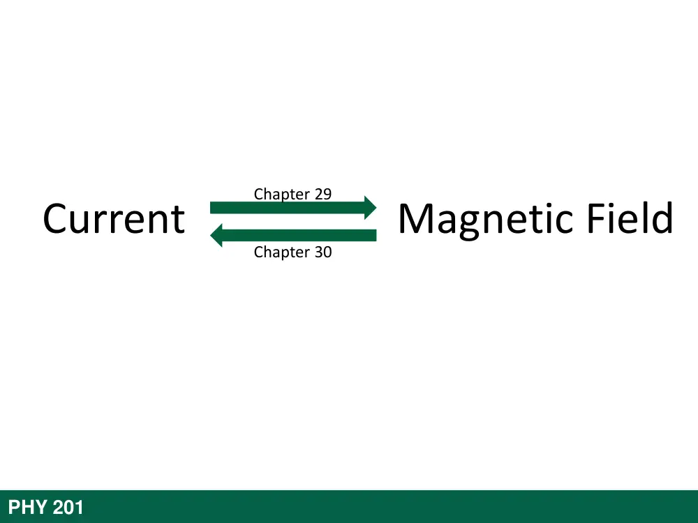
Current Magnetic Field
Chapter 29
Chapter 30
30-1 Faraday’s Law and Lenz’s Law
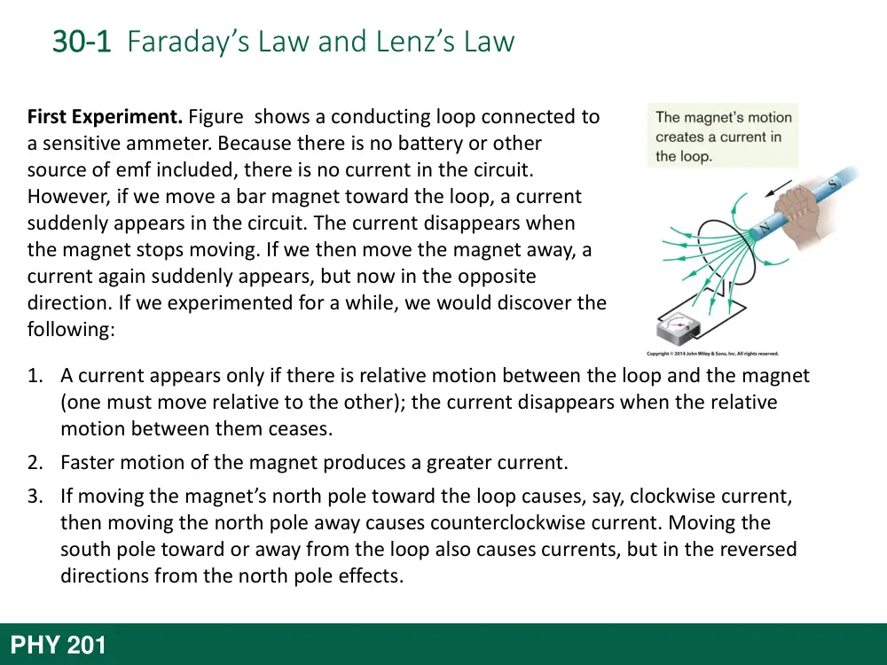
First Experiment. Figure shows a conducting loop connected to
a sensitive ammeter. Because there is no battery or other
source of emf included, there is no current in the circuit.
However, if we move a bar magnet toward the loop, a current
suddenly appears in the circuit. The current disappears when
the magnet stops moving. If we then move the magnet away, a
current again suddenly appears, but now in the opposite
direction. If we experimented for a while, we would discover the
following:
1. A current appears only if there is relative motion between the loop and the magnet
(one must move relative to the other); the current disappears when the relative
motion between them ceases.
2. Faster motion of the magnet produces a greater current.
3. If moving the magnet’s north pole toward the loop causes, say, clockwise current,
then moving the north pole away causes counterclockwise current. Moving the
south pole toward or away from the loop also causes currents, but in the reversed
directions from the north pole effects.
PHY 201
30-1 Faraday’s Law and Lenz’s Law
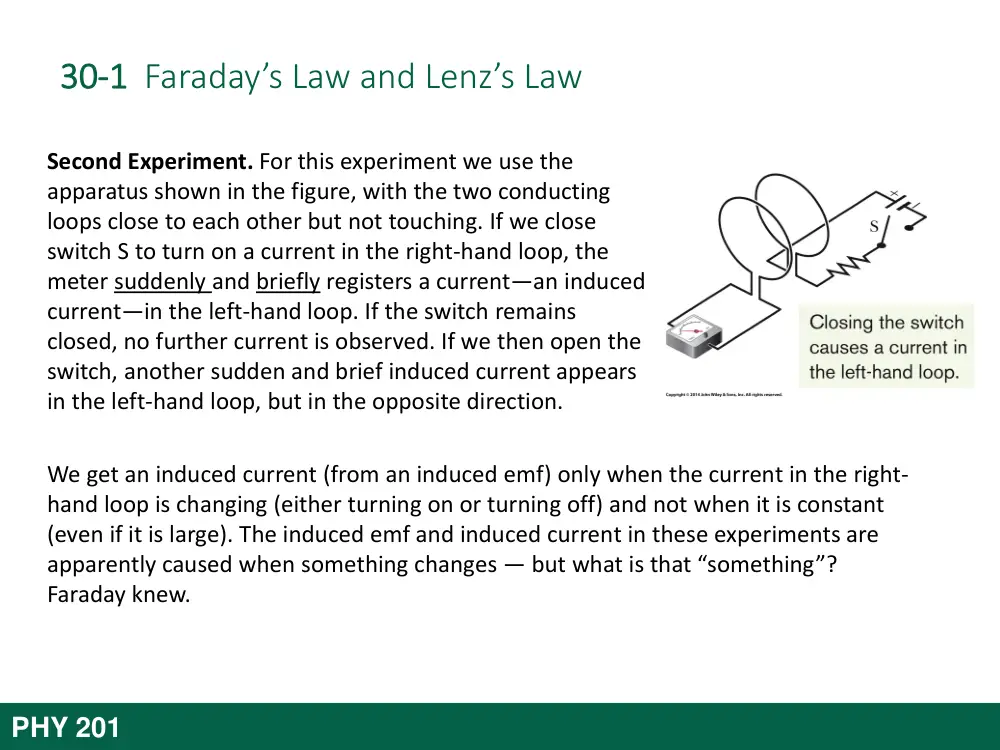
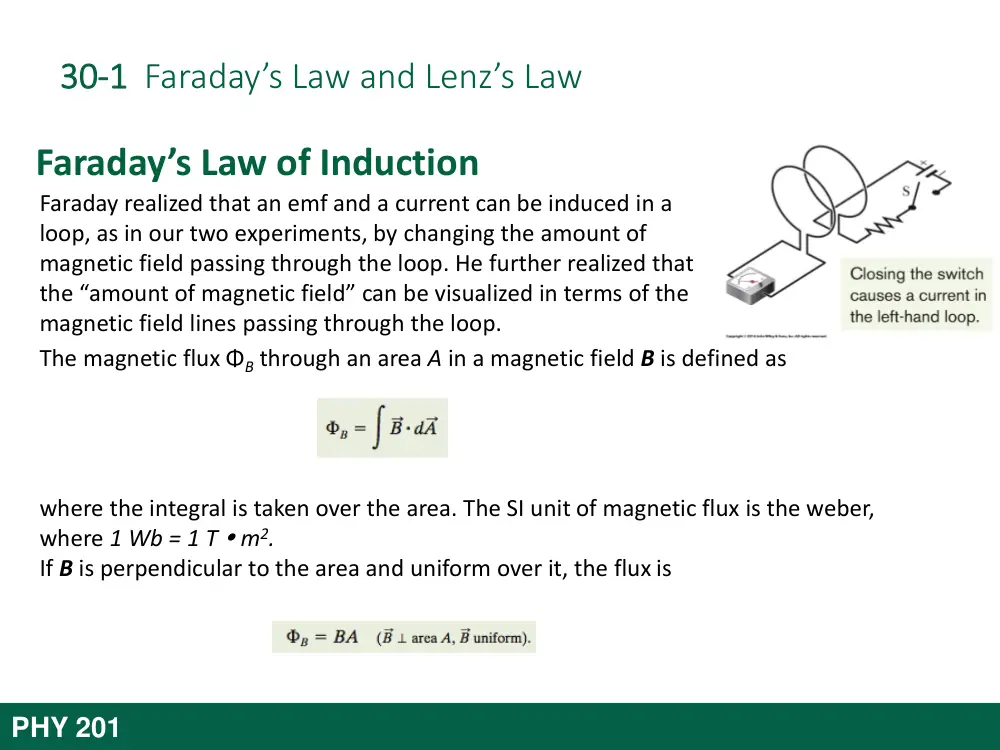
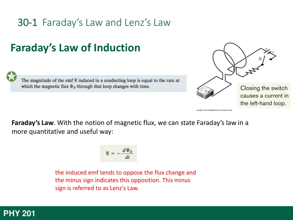
Second Experiment. For this experiment we use the
apparatus shown in the figure, with the two conducting
loops close to each other but not touching. If we close
switch S to turn on a current in the right-hand loop, the
meter suddenly and briefly registers a current—an induced
current—in the left-hand loop. If the switch remains
closed, no further current is observed. If we then open the
switch, another sudden and brief induced current appears
in the left-hand loop, but in the opposite direction.
We get an induced current (from an induced emf) only when the current in the right-
hand loop is changing (either turning on or turning off) and not when it is constant
(even if it is large). The induced emf and induced current in these experiments are
apparently caused when something changes — but what is that “something”?
Faraday knew.
PHY 201
PHY 305
Induction and Faraday law
Magnetic flux
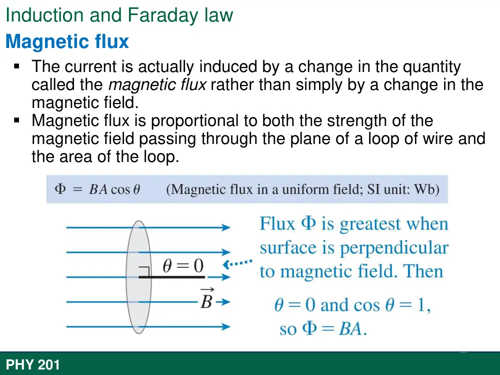
The current is actually induced by a change in the quantity
called the magnetic flux rather than simply by a change in the
magnetic field.
Magnetic flux is proportional to both the strength of the
magnetic field passing through the plane of a loop of wire and
the area of the loop.
PHY 201
PHY 305
Induction and Faraday law
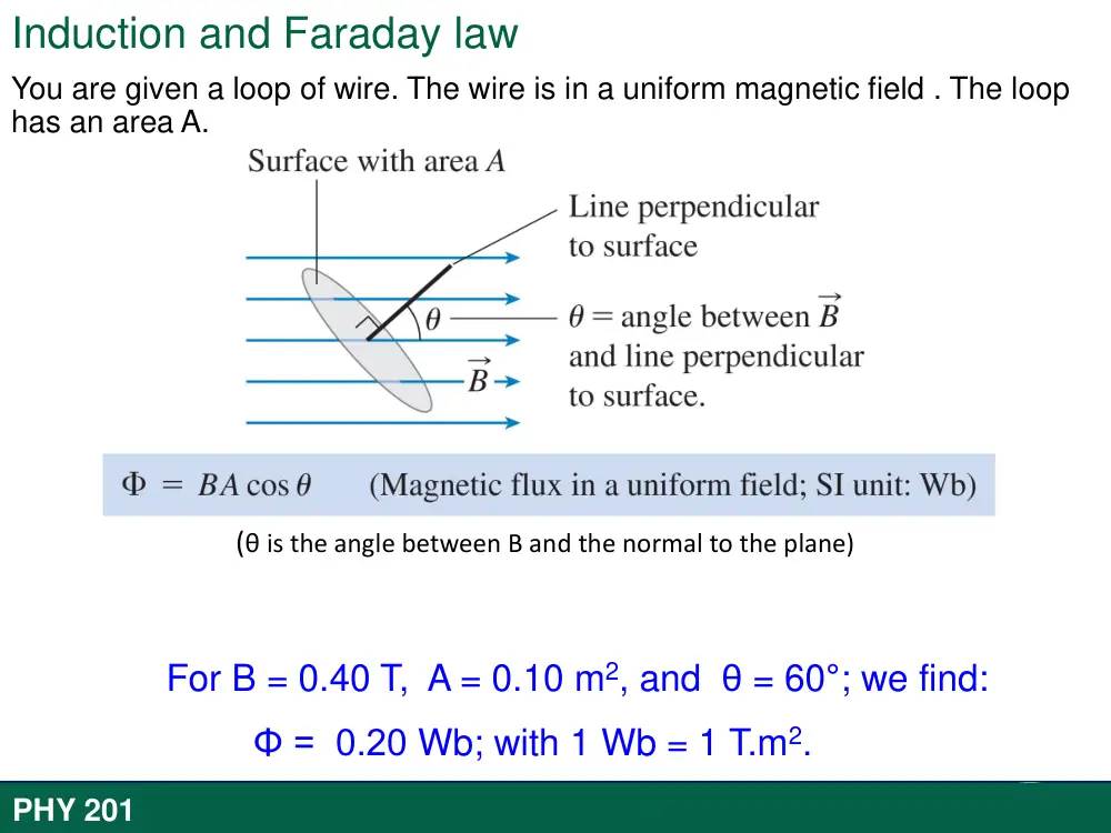
You are given a loop of wire. The wire is in a uniform magnetic field . The loop
has an area A.
(θ is the angle between B and the normal to the plane)
For B = 0.40 T, A = 0.10 m2, and θ = 60°; we find:
Φ = 0.20 Wb; with 1 Wb = 1 T.m2.
PHY 201
PHY 305
Induction and Faraday law
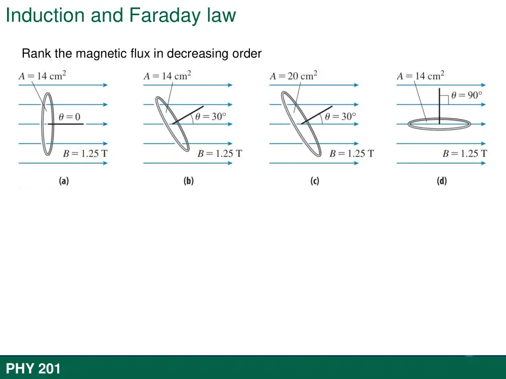
Rank the magnetic flux in decreasing order
PHY 201
30-1 Faraday’s Law and Lenz’s Law
The magnetic flux ΦB through an area A in a magnetic field B is defined as
where the integral is taken over the area. The SI unit of magnetic flux is the weber,
where 1 Wb = 1 T m2.
If B is perpendicular to the area and uniform over it, the flux is
Faraday’s Law of Induction
Faraday realized that an emf and a current can be induced in a
loop, as in our two experiments, by changing the amount of
magnetic field passing through the loop. He further realized that
the “amount of magnetic field” can be visualized in terms of the
magnetic field lines passing through the loop.
PHY 201
30-1 Faraday’s Law and Lenz’s Law
Faraday’s Law. With the notion of magnetic flux, we can state Faraday’s law in a
more quantitative and useful way:
Faraday’s Law of Induction
the induced emf tends to oppose the flux change and
the minus sign indicates this opposition. This minus
sign is referred to as Lenz’s Law.
PHY 201
30-1 Faraday’s Law and Lenz’s Law
Lenz’s Law
An induced current has a direction such that the magnetic field due to this induced
current opposes the change in the magnetic flux that induces the current. The induced
emf has the same direction as the induced current.
Lenz’s law at work. As the magnet is
moved toward the loop, a current is
induced in the loop. The current
produces its own magnetic field, with
magnetic dipole moment μ oriented so as
to oppose the motion of the magnet.
Thus, the induced current must be
counterclockwise as shown.
PHY 201
PHY 305
Induction and Faraday law
ΦB
B and Bin have opposite directions
ΦB
B and Bin have same direction
When applying Lenz’ Law, there are two magnetic fields
to consider:
- B: The external changing magnetic field
- B induced: The magnetic field produced by the
current in the loop.
PHY 201
30-1 Faraday’s Law and Lenz’s Law
Lenz’s Law
The direction of the current i induced in a loop is such that the current’s magnetic field Bind opposes the change
in the magnetic field B inducing i. The field Bind is always directed opposite an increasing field B (a, c) and in the
same direction as a decreasing field B (b, d ). The curled – straight right-hand rule gives the direction of the
induced current based on the direction of the induced field.
PHY 201
PHY 305
Induction and Faraday law
Find the direction of the induced current in each.
PHY 201
30-2
Induction and Energy Transfer
30-2 Induction and Energy Transfer
In the figure, a rectangular loop of wire of width L has one
end in a uniform external magnetic field that is directed
perpendicularly into the plane of the loop. This field may be
produced, for example, by a large electromagnet. The
dashed lines in the figure show the assumed limits of the
magnetic field; the fringing of the field at its edges is
neglected. You are to pull this loop to the right at a constant
velocity v.
Flux change: Therefore, in the figure a magnetic field and a conducting loop are in
relative motion at speed v and the flux of the field through the loop is changing with
time (here the flux is changing as the area of the loop still in the magnetic field is
changing).
Rate of Work: To pull the loop at a constant velocity v, you must apply a constant
force F to the loop because a magnetic force of equal magnitude but opposite
direction acts on the loop to oppose you. The rate at which you do work — that is,
the power — is then
where F is the magnitude of the force you apply to the loop.
PHY 201
30-2 Induction and Energy Transfer
Induced emf: To find the current, we first apply Faraday’s
law. When x is the length of the loop still in the magnetic
field, the area of the loop still in the field is Lx. Then, the
magnitude of the flux through the loop is
As x decreases, the flux decreases. Faraday’s law tells us that
with this flux i decrease, an emf is induced in the loop. We
can write the magnitude of this emf as
in which we have replaced dx/dt with v, the speed at which the loop
moves.
A circuit diagram for
the loop of above
figure while the loop
is moving.
PHY 201
30-2 Induction and Energy Transfer
Induced Current: Figure (bottom) shows the loop as a
circuit: induced emf is represented on the left, and the
collective resistance R of the loop is represented on the
right. To find the magnitude of the induced current, we can
apply the equation
which gives
In the Fig. (top), the deflecting forces acting on the three
segments of the loop are marked F1, F2, and F3. Note,
however, that from the symmetry, forces F2 and F3 are equal
in magnitude and cancel. This leaves only force F1, which is
directed opposite your force F on the loop and thus is the
force opposing you.
A circuit diagram for
the loop of above
figure while the loop
is moving.
PHY 201
30-2 Induction and Energy Transfer
So, F = -F1. the magnitude of F1 thus
where the angle between B and the length vector L for the
left segment is 90°. This gives us
Because B, L, and R are constants, the speed v at which you move the
loop is constant if the magnitude F of the force you apply to the loop
is also constant.
Rate of Work: We find the rate at which you do work on the loop as
you pull it from the magnetic field:
NOTE: The work that you do in pulling the loop through the
magnetic field appears as thermal energy in the loop.
A circuit diagram for
the loop of above
figure while the loop
is moving.
PHY 201
30-4
Inductors and Inductance
30-4 Inductors and Inductance
The crude inductors with which
Michael Faraday discovered the law
of induction. In those days
amenities such as insulated wire
were not commercially available. It
is said that Faraday insulated his
wires by wrapping them with strips
cut from one of his wife’s petticoats.
An inductor is a device that can be used to produce a
known magnetic field in a specified region. If a
current i is established through each of the N
windings of an inductor, a magnetic flux ΦB links
those windings. The inductance L of the inductor is
The SI unit of inductance is the henry (H), where 1
henry = 1H=1Tm2/A.
The inductance per unit length near the middle of a
long solenoid of cross-sectional area A and n turns
per unit length is
PHY 201
30-5
Self-Induction
30-5 Self-Induction
If two coils — which we can now call inductors — are near
each other, a current i in one coil produces a magnetic flux
ΦB through the second coil. We have seen that if we
change this flux by changing the current, an induced emf
appears in the second coil according to Faraday’s law. An
induced emf appears in the first coil as well. This process
(see Figure) is called self-induction, and the emf that
appears is called a
self-induced emf. It obeys Faraday’s law of induction just as other induced emfs do.
For any inductor,
Faraday’s law tells us that
By combining these equations, we can write
Note: Thus, in any inductor (such as a
coil, a solenoid, or a toroid) a self-
induced emf appears whenever the
current changes with time. The
magnitude of the current has no
influence on the magnitude of the
induced emf; only the rate of change
of the current counts.
PHY 201
30-6
RL Circuits
PHY 201
A first order non-homogeneous differential equation:
𝑎
𝑑𝑖(𝑡)
𝑑𝑡 + 𝑏𝑖 𝑡 + 𝑐 = 0 where a,b,c are constants
General solution:
i 𝑡 = 𝐾𝑒−𝑏
𝑎𝑡 +
𝑐
𝑏 [𝑒−𝑏
𝑎𝑡 − 1]
𝑖 𝑡 = ℰ
𝑅 [1 − 𝑒−𝑅
𝐿𝑡]
i 𝑡 =
ℰ
𝑅 𝑒−𝑅
𝐿𝑡
30-6 RL Circuits
If a constant emf is introduced into a single-loop circuit containing a
resistance R and an inductance L, the current rises to an equilibrium
value of /R according to
Here τL, the inductive time constant, is given by
An RL circuit.
Plot (a) and (b) shows how the potential
differences VR (= iR) across the resistor and VL (= L
di/dt) across the inductor vary with time for
particular values of , L, and R.
When the source of constant emf is removed and
replaced by a conductor, the current decays from a
value i0 according to
The variation with time of (a) VR, the
potential difference across the resistor in
the circuit (top), and (b) VL, the potential
difference across the inductor in that
circuit.
PHY 201
30-7
Energy Stored in a Magnetic Field
30-7 Energy Stored in a Magnetic Field
An RL circuit.
If an inductor L carries a current i, the inductor’s magnetic field stores an energy given
by
PHY 201
30-8
Mutual inductance
30-8 Mutual Induction
If coils 1 and 2 are near each other, a changing current in either coil can induce an emf
in the other. This mutual induction is described by
and
Mutual induction. (a) The magnetic
field B1 produced by current i1 in coil
1 extends through coil 2. If i1 is
varied (by varying resistance R), an
emf is induced in coil 2 and current
registers on the meter connected to
coil 2. (b) The roles of the coils
interchanged.
PHY 201
CHAPTER 31
Electromagnetic Oscillations
and Alternating Current
31-1
Electromagnetic Oscillations
31-1 Electromagnetic Oscillations
Eight stages in a single cycle of
oscillation of a resistance less LC
circuit. The bar graphs by each
figure show the stored magnetic
and electrical energies. The
magnetic field lines of the
inductor and the electric field
lines of the capacitor are shown.
(a) Capacitor with maximum
charge, no current. (b) Capacitor
discharging, current increasing.
(c) Capacitor fully discharged,
current maximum. (d) Capacitor
charging but with polarity
opposite that in (a), current
decreasing.
(e) Capacitor with maximum charge having polarity opposite that in (a), no current. ( f ) Capacitor
discharging, current increasing with direction opposite that in (b). (g) Capacitor fully discharged,
current maximum. (h) Capacitor charging, current decreasing.
PHY 201
31-1 Electromagnetic Oscillations
Parts (a) through (h) of the Figure
show succeeding stages of the
oscillations in a simple LC circuit. The
energy stored in the electric field of
the capacitor at any time is
where q is the charge on the capacitor
at that time. The energy stored in the
magnetic field of the inductor at any
time is
where i is the current through the
inductor at that time.
The resulting oscillations of the capacitor’s electric field and the inductor’s magnetic field
are said to be electromagnetic oscillations.
PHY 201
PHY 201
31-1 Electromagnetic Oscillations
From the table we can deduce the correspondence between these
systems. Thus,
q corresponds to x, 1/C corresponds to k,
i corresponds to v, and L corresponds to m.
The correspondences listed above suggest that to find the angular
frequency of oscillation for an ideal (resistanceless) LC circuit, k should be
replaced by 1/C and m by L, yielding
PHY 201
31-1 Electromagnetic Oscillations
LC Oscillator
The total energy U present at any instant in an oscillating LC circuit is given by
in which UB is the energy stored in the magnetic field of the inductor and UE is the
energy stored in the electric field of the capacitor. Since we have assumed the circuit
resistance to be zero, no energy is transferred to thermal energy and U remains constant
with time. In more formal language, dU/dt must be zero. This leads to
However, i = dq/dt and di/dt = d2q/dt2. With these substitutions, we get
This is the differential equation that describes the oscillations of a resistanceless LC
circuit.
PHY 201
31-1 Electromagnetic Oscillations
Charge and Current Oscillation
The solution for the differential equation equation that describes the oscillations of a
resistanceless LC circuit is
where Q is the amplitude of the charge variations, ω is the angular frequency of the
electromagnetic oscillations, and ϕ is the phase constant. Taking the first derivative of
the above Eq. with respect to time gives us the current:
Answer: (a) εL= 12 V
(b) UB=150 μJ
PHY 201
31-1 Electromagnetic Oscillations
Electrical and Magnetic Energy Oscillations
The electrical energy stored in the LC circuit at time t is,
The magnetic energy is,
Figure shows plots of UE (t) and UB (t) for the case of ϕ=0. Note
that
1. The maximum values of UE and UB are both Q2/2C.
2. At any instant the sum of UE and UB is equal to Q2/2C, a
constant.
3. When UE is maximum, UB is zero, and conversely.
The stored magnetic
energy and electrical
energy in the RL circuit as
a function of time.
PHY 201
31-2
Damped Oscillation in an RLC circuit
31-2 Damped Oscillation in an RLC circuit
A series RLC circuit. As the
charge contained in the circuit
oscillates back and forth
through the resistance,
electromagnetic energy is
dissipated as thermal energy,
damping (decreasing the
amplitude of) the oscillations.
To analyze the oscillations of this circuit, we write an equation
for the total electromagnetic energy U in the circuit at any
instant. Because the resistance does not store electromagnetic
energy, we can write
Now, however, this total energy decreases as energy is
transferred to thermal energy. The rate of that transfer is,
where the minus sign indicates that U decreases. By
differentiating U with respect to time and then substituting
the result we eventually get,
which is the differential equation for damped oscillations in an
RLC circuit.
Charge Decay. The solution to above Eq. is
in which
and .
PHY 201
31-3
Forced Oscillations of
Three Simple Circuits
31-3 Forced Oscillations of Three Simple Circuits
Forced Oscillations
PHY 201
31-3 Forced Oscillations of Three Simple Circuits
Resistive Load
The alternating potential difference across a resistor has
amplitude
where VR and IR are the amplitudes of alternating current iR and
alternating potential difference vr across the resistance in the circuit.
Angular speed: Both current and potential difference
phasors rotate counterclockwise about the origin with an
angular speed equal to the angular frequency ωd of vR and
iR.
Length: The length of each phasor represents the
amplitude of the alternating quantity: VR for the voltage
and IR for the current.
Projection: The projection of each phasor on the vertical
axis represents the value of the alternating quantity at time
t: vR for the voltage and iR for the current.
Rotation angle: The rotation angle of each phasor is equal
to the phase of the alternating quantity at time t.
A resistor is
connected across an
alternating-current
generator.
(a) The current iR and the potential
difference vR across the resistor are plotted
on the same graph, both versus time t.
They are in phase and complete one cycle
in one period T. (b) A phasor diagram
shows the same thing as (a).
PHY 201
31-3 Forced Oscillations of Three Simple Circuits
Inductive Load
The inductive reactance of an inductor is defined as
Its value depends not only on the inductance but also on the
driving angular frequency ωd.
The voltage amplitude and current amplitude are related by
Fig. (left), shows that the quantities iL
and vL are 90° out of phase. In this case,
however, iL lags vL; that is, monitoring the
current iL and the potential difference vL
in the circuit of Fig. (top) shows that iL
reaches its maximum value after vL does,
by one-quarter cycle.
PHY 201
An inductor is connected
across an alternating-
current generator.
31-3 Forced Oscillations of Three Simple Circuits
Capacitive Load
The capacitive reactance of a capacitor, defined as
Its value depends not only on the capacitance but also on the
driving angular frequency ωd.
The voltage amplitude and current amplitude are related by
In the phasor diagram we see that iC
leads vC, which means that, if you
monitored the current iC and the
potential difference vC in the circuit
above, you would find that iC reaches its
maximum before vC does, by one-quarter
cycle.
PHY 201
A capacitor is connected
across an alternating-
current generator.
31-4
The Series RLC Circuits
31-4 The Series RLC Circuit
Series RLC circuit with
an external emf
For a series RLC circuit with an external emf
given by
The current is given by
the current amplitude is given by
The denominator in the above equation is called the impedance Z of the circuit for
the driving angular frequency ωd.
If we substitute the value of XL and XC in the equation for current (I), the equation
becomes:
PHY 201
31-4 The Series RLC Circuits
From the right-hand phasor triangle in Fig.(d) we can write
Phase Constant
The current amplitude I is maximum when the driving angular frequency ωd equals the
natural angular frequency ω of the circuit, a condition known as resonance. Then XC= XL,
ϕ = 0, and the current is in phase with the emf.
Series RLC circuit with
an external emf
PHY 201
31-5
Power in Alternating-Current Circuits
31-5 Power in Alternating-Current Circuits
The instantaneous rate at which energy is dissipated in the resistor
can be written as
Over one complete cycle, the average value of sinθ, where θ is any
variable, is zero (Fig.a) but the average value of sin2θ is 1/2(Fig.b).
Thus the power is,
The quantity I/ √2 is called the root-mean-square, or rms, value of
the current i:
We can also define rms values of voltages and emfs for alternating-
current circuits:
In a series RLC circuit, the average power Pavg of the generator is
equal to the production rate of thermal energy in the resistor:
(a) A plot of sinθ versus θ.
The average value over
one cycle is zero.
(b) A plot of sin2θ versus θ
. The average value over
one cycle is 1/2.
PHY 201
31-6
Transformers
31-6 Transformers
A transformer (assumed to be ideal) is an iron core on
which are wound a primary coil of Np turns and a
secondary coil of Ns turns. If the primary coil is
connected across an alternating-current generator, the
primary and secondary voltages are related by
An ideal transformer (two coils
wound on an iron core) in a basic
trans- former circuit. An ac
generator produces current in the
coil at the left (the primary). The
coil at the right (the secondary) is
connected to the resistive load R
when switch S is closed.
Energy Transfers. The rate at which the generator transfers
energy to the primary is equal to IpVp. The rate at which
the primary then transfers energy to the secondary (via the
alternating magnetic field linking the two coils) is IsVs.
Because we assume that no energy is lost along the way,
conservation of energy requires that
The equivalent resistance of the secondary circuit, as
seen by the generator, is
PHY 201
31-6
Summary
CHAPTER 32
Maxwell Equations;
Magnetism of Matter
32-1
Gauss’ Law for Magnetic Fields
32-1 Induced Magnetic Fields
Gauss’ law for magnetic fields is a formal way of saying
that magnetic monopoles do not exist. The law asserts
that the net magnetic flux ΦB through any closed
Gaussian surface is zero:
Contrast this with Gauss’ law for electric fields,
If you break a
magnet, each
fragment becomes a
separate magnet,
with its own north
and south poles.
The field lines for the
magnetic field B of a short
bar magnet. The red curves
represent cross sections of
closed, three-dimensional
Gaussian surfaces.
Gauss’ law for magnetic fields says that there
can be no net magnetic flux through the
surface because there can be no net “magnetic
charge” (individual magnetic poles) enclosed
by the surface.
PHY 201
32-2
Induced Magnetic Field
32-2 Induced Magnetic Fields
A changing electric flux induces a magnetic field B. Maxwell’s Law,
Relates the magnetic field induced along a closed loop to the
changing electric flux ϕE through the loop.
Charging a Capacitor.
As an example of this sort of induction, we consider the
charging of a parallel-plate capacitor with circular plates. The
charge on our capacitor is being increased at a steady rate
by a constant current i in the connecting wires. Then the
electric field magnitude between the plates must also be
increasing at a steady rate.
PHY 201
32-2 Induced Magnetic Fields
A changing electric flux induces a magnetic field B. Maxwell’s Law,
Relates the magnetic field induced along a closed loop to the
changing electric flux ϕE through the loop.
PHY 201
32-2 Induced Magnetic Fields
Ampere-Maxwell Law
Ampere’s law,
gives the magnetic field generated by a current ienc encircled by a
closed loop.
Thus, the two equations (the other being Maxwell’s Law) that
specify the magnetic field B produced by means other than a
magnetic material (that is, by a current and by a changing electric
field) give the field in exactly the same form. We can combine the
two equations into the single equation:
PHY 201