
PHY 201 Chapter 26, Fall 2017
Lebanese American University · Electricit and Magnetism · 54 pages · Dr. Jimmy Romanos


Showing the first 10 of 54 pages. Download the PDF to see all of it.
More PHY 201 files
Show the text of this chapter
CHAPTER 26
Current and Resistance
Electric Current
26-1
26-1 Electric Current
PHY 201
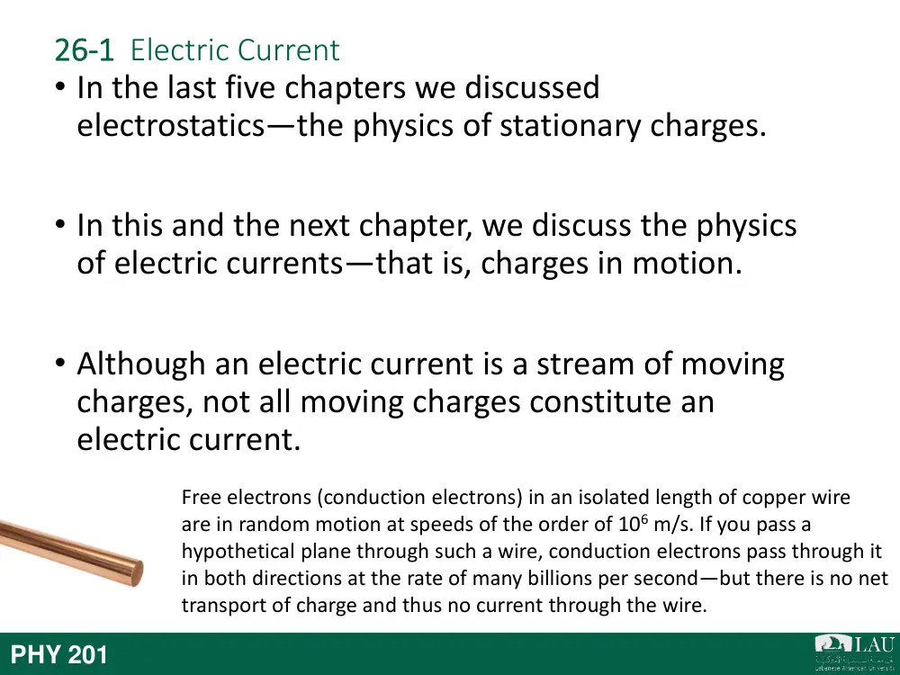
• In the last five chapters we discussed
electrostatics—the physics of stationary charges.
• In this and the next chapter, we discuss the physics
of electric currents—that is, charges in motion.
• Although an electric current is a stream of moving
charges, not all moving charges constitute an
electric current.
Free electrons (conduction electrons) in an isolated length of copper wire
are in random motion at speeds of the order of 106 m/s. If you pass a
hypothetical plane through such a wire, conduction electrons pass through it
in both directions at the rate of many billions per second—but there is no net
transport of charge and thus no current through the wire.
26-1 Electric Current
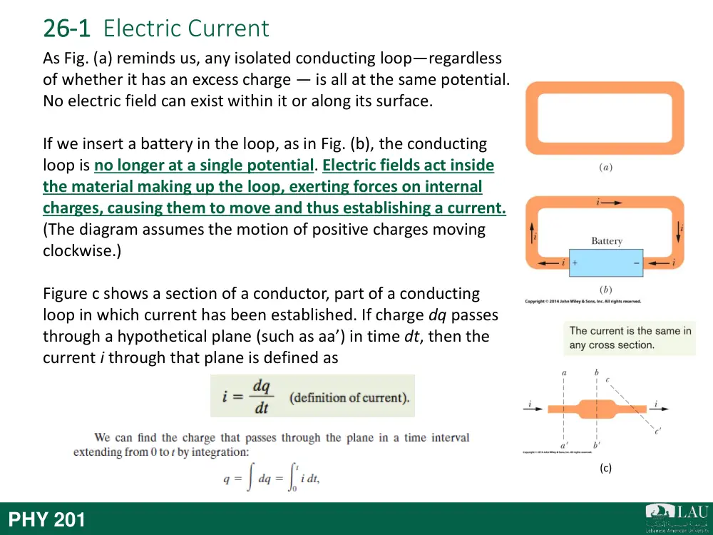
As Fig. (a) reminds us, any isolated conducting loop—regardless
of whether it has an excess charge — is all at the same potential.
No electric field can exist within it or along its surface.
If we insert a battery in the loop, as in Fig. (b), the conducting
loop is no longer at a single potential. Electric fields act inside
the material making up the loop, exerting forces on internal
charges, causing them to move and thus establishing a current.
(The diagram assumes the motion of positive charges moving
clockwise.)
Figure c shows a section of a conductor, part of a conducting
loop in which current has been established. If charge dq passes
through a hypothetical plane (such as aa’) in time dt, then the
current i through that plane is defined as
(c)
PHY 201
26-1 Electric Current
PHY 201
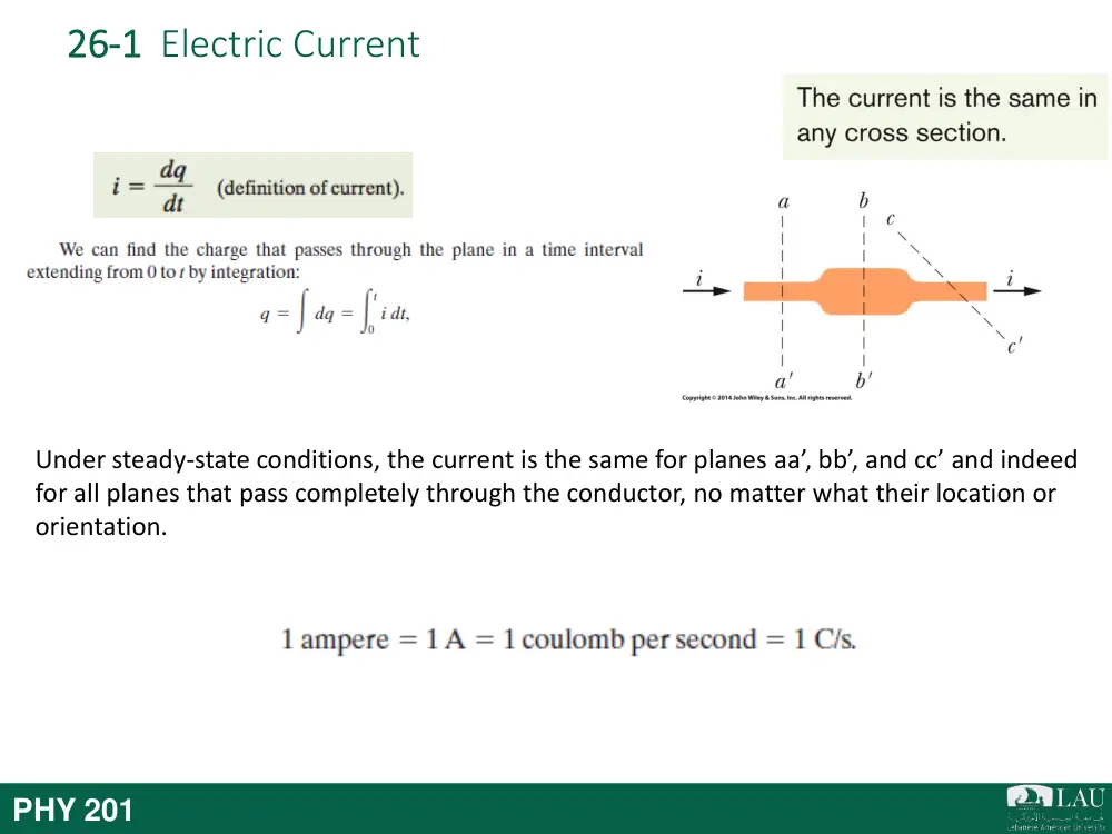
Under steady-state conditions, the current is the same for planes aa’, bb’, and cc’ and indeed
for all planes that pass completely through the conductor, no matter what their location or
orientation.
26-1 Electric Current
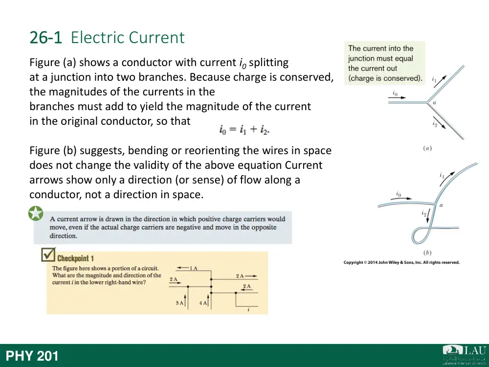
Figure (a) shows a conductor with current i0 splitting
at a junction into two branches. Because charge is conserved,
the magnitudes of the currents in the
branches must add to yield the magnitude of the current
in the original conductor, so that
Figure (b) suggests, bending or reorienting the wires in space
does not change the validity of the above equation Current
arrows show only a direction (or sense) of flow along a
conductor, not a direction in space.
PHY 201
26-1 Electric Current
Figure (a) shows a conductor with current i0 splitting
at a junction into two branches. Because charge is conserved,
the magnitudes of the currents in the
branches must add to yield the magnitude of the current
in the original conductor, so that
Figure (b) suggests, bending or reorienting the wires in space
does not change the validity of the above equation Current
arrows show only a direction (or sense) of flow along a
conductor, not a direction in space.
Answer: 8A with arrow
pointing right
PHY 201
Electric Current
26-2
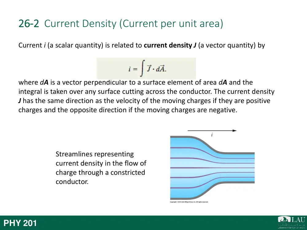
26-2 Current Density (Current per unit area)
Current i (a scalar quantity) is related to current density J (a vector quantity) by
where dA is a vector perpendicular to a surface element of area dA and the
integral is taken over any surface cutting across the conductor. The current density
J has the same direction as the velocity of the moving charges if they are positive
charges and the opposite direction if the moving charges are negative.
Streamlines representing
current density in the flow of
charge through a constricted
conductor.
PHY 201
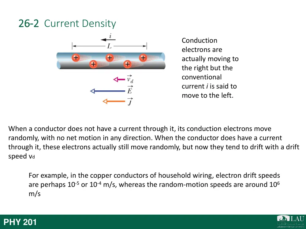
26-2 Current Density
Conduction
electrons are
actually moving to
the right but the
conventional
current i is said to
move to the left.
PHY 201
When a conductor does not have a current through it, its conduction electrons move
randomly, with no net motion in any direction. When the conductor does have a current
through it, these electrons actually still move randomly, but now they tend to drift with a drift
speed vd
For example, in the copper conductors of household wiring, electron drift speeds
are perhaps 10-5 or 10-4 m/s, whereas the random-motion speeds are around 106
m/s
26-2 Current Density
Current is said to be due to positive charges that are propelled by the electric field. In
the figure, positive charge carriers drift at speed vd in the direction of the applied
electric field E which here is applied to the left. By convention, the direction of the
current density J and the sense of the current arrow are drawn in that same direction,
as is the drift speed vd.
The drift velocity vd is related to the current density by
Here the product ne, whose SI unit is the coulomb per cubic meter (C/m3), is the
carrier charge density.
Conduction
electrons are
actually moving to
the right but the
conventional
current i is said to
move to the left.
PHY 201
Resistance and
Resistivity
26-3
26-3 Resistance and Resistivity
If we apply the same potential difference between the ends of geometrically similar rods of
copper and of glass, very different currents result. The characteristic of the conductor that
enters here is its electrical resistance. The resistance R of a conductor is defined as
where V is the potential difference across the conductor and i is the current through the
conductor. Instead of the resistance R of an object, we may deal with the resistivity ρ of the
material:
The reciprocal of resistivity is conductivity σ of the
material:
Assortment of Resistors
PHY 201
A conductor whose function in a circuit is to
provide a specified resistance is called a resistor
Objects: Resistance
Materials: Resistivity
26-3 Resistance and Resistivity
PHY 201
26-3 Resistance and Resistivity
PHY 201
This equation hold only for isotropic materials—materials
whose electrical properties are the same in all directions
26-3 Resistance and Resistivity
The resistance R of a conducting wire of length L and uniform cross section is
Here A is the cross-sectional area.
A potential difference V is applied
between the ends of a wire of length
L and cross section A, establishing a
current i.
The resistivity ρ for most materials changes with
temperature. For many materials, including metals, the
relation between ρ and temperature T is approximated
by the equation
Here T0 is a reference temperature, ρ0 is the resistivity at
T0, and α is the temperature coefficient of resistivity for
the material.
The resistivity of copper as a function
of temperature.
PHY 201
Ohm’s Law
26-3
26-4 Ohm’s Law
Figure (a) shows how to distinguish among devices. A potential
difference V is applied across the device being tested, and the
resulting current i through the device is measured as V is
varied in both magnitude and polarity.
Figure (b) is a plot of i versus V for one device. This plot is a
straight line passing through the origin, so the ratio i/V (which
is the slope of the straight line) is the same for all values of V.
This means that the resistance R = V/i of the device is
independent of the magnitude and polarity of the applied
potential difference V.
Figure (c) is a plot for another conducting device. Current can
exist in this device only when the polarity of V is positive and
the applied potential difference is more than about 1.5 V.
When current does exist, the relation between i and V is not
linear; it depends on the value of the applied potential
difference V.
PHY 201
26-4 Ohm’s Law
I ~ V or I = V/R
PHY 201
Bonus slide (not the exam)!
- General relativity: The
current description of
gravitation in modern physics
- Quantum Physics: The
physics that governs the
behavior of matter and light
at the atomic (and
subatomic) scale
Good documentaries to watch: The
Elegant Universe (Nova, PBS)
PHY 201
Schrödinger's cat
26-4 Ohm’s Law
A Microscopic View
The assumption that the conduction electrons in a
metal are free to move like the molecules in a gas
leads to an expression for the resistivity of a metal:
Here n is the number of free electrons per unit
volume and τ is the mean time between the collisions
of an electron with the atoms of the metal.
Metals obey Ohm’s law because the mean free time τ
is approximately independent of the magnitude E of
any electric field applied to a metal.
The gray lines show an electron
moving from A to B, making six
collisions en route. The green lines
show what the electron’s path
might be in the presence of an
applied electric field E. Note the
steady drift in the direction
of -E.
PHY 201
General Knowledge
Power, Semiconductors,
Superconductors
26-3
26-5 Power, Semiconductors, Superconductors
Figure shows a circuit consisting of a battery B that is connected by
wires, which we assume have negligible resistance, to an unspecified
conducting device. The device might be a resistor, a storage battery (a
rechargeable battery), a motor, or some other electrical device. The
battery maintains a potential difference of magnitude V across its own
terminals and thus (because of the wires) across the terminals of the
unspecified device, with a greater potential at terminal a of the device
than at terminal b.
The power P, or rate of energy transfer, in an electrical device across
which a potential difference V is maintained is
If the device is a resistor, the power can also be written as
or,
PHY 201
26-5 Power, Semiconductors, Superconductors
Semiconductors are materials that have few conduction electrons but can become
conductors when they are doped with other atoms that contribute charge carriers.
In a semiconductor, n (number of free
electrons) is small (unlike conductor) but
increases very rapidly with temperature as the
increased thermal agitation makes more
charge carriers available. This causes a
decrease of resistivity with increasing
temperature, as indicated
by the negative temperature coefficient
of resistivity for silicon in Table 26-2.
Superconductors are materials that lose all electrical
resistance below some critical temperature. Most such
materials require very low temperatures, but some
become superconducting at temperatures as high as room
temperature.
The resistance of mercury drops to zero
at a temperature of about 4 K.
PHY 201
26 Summary
Current
• The electric current i in a conductor is
defined by
Current Density
• Current is related to current density by
Eq. 26-1
Eq. 26-4
Resistance of a Conductor
• Resistance R of a conductor is defined
by
• Similarly the resistivity and
conductivity of a material is defined by
• Resistance of a conducting wire of
length L and uniform cross section is
Eq. 26-8
Eq. 26-7
Eq. 26-10&12
Change of ρ with Temperature
• The resistivity of most material
changes with temperature and is given
as
Eq. 26-16
Eq. 26-17
Drift Speed of the Charge Carriers
• Drift speed of the charge carriers in an
applied electric field is related to
current density by
PHY 201
26 Summary
Ohm’s Law
• A given device (conductor, resistor, or
any other electrical device) obeys
Ohm’s law if its resistance R (defined
by Eq. 26-8 as V/i) is independent of
the applied potential difference V.
Power
• The power P, or rate of energy transfer,
in an electrical device across which a
potential difference V is maintained is
• If the device is a resistor, we can write
Eq. 26-26
Eq. 26-22
Eq. 26-27&28
Resistivity of a Metal
• By assuming that the conduction
electrons in a metal are free to move
like the molecules of a gas, it is possible
to derive an expression for the
resistivity of a metal:
PHY 201
CHAPTER 27
Circuits
Electric Current
27-1
27-1 Single-Loop Circuits
To produce a steady flow of charge, you need a “charge pump,” a device that—by
doing work on the charge carriers—maintains a potential difference between a pair of
terminals. We call such a device an emf device, and the device is said to provide an
emf , which means that it does work on charge carriers.
PHY 201
emf: electromotive force
An emf device supplies the energy for the motion (of charge) via the work it does
and thus maintain a potential difference between its terminal
Emf devices:
-
Battery
-
Electric generator
-
Solar cells
-
Fuel cells
-
Human beings
-
Electric eels (600 V)
Electric eels
Hydrogen Fuel cells (Honda CFX clarity)
Battery (Chevy Volt)
Solar cells
Figure shows an emf device (consider it to be a
battery) that is part of a simple circuit
containing a single resistance R. The emf
device keeps one of its terminals (called the
positive terminal and often labeled +) at a
higher electric potential than the other
terminal (called the negative terminal and
labeled -). We can represent the emf of the
device with an arrow that points from the
negative terminal toward the positive terminal
as in Figure. A small circle on the tail of the
emf arrow distinguishes it from the arrows that
indicate current direction.
27-1 Single-Loop Circuits
PHY 201
27-1 Single-Loop Circuits
An emf device does work on charges to maintain a potential difference between its
output terminals. If dW is the work the device does to force positive charge dq from
the negative to the positive terminal, then the emf (work per unit charge) of the
device is
An ideal emf device is one that lacks any
internal resistance. The potential difference
between its terminals is equal to the emf.
A real emf device has internal resistance. The
potential difference between its terminals is
equal to the emf only if there is no current
through the device.
PHY 201
emf is the work per unit charge that the device
does in moving charge from its low-potential
terminal to its high-potential terminal.
27-1 Single-Loop Circuits
Calculating Current in a Single-Loop Circuits
After making a complete loop, our initial potential, as modified
for potential changes along the way, must be equal to our final
potential; that is,
The value of Va cancels from this equation, which becomes
Which gives us
In the figure, let us start at point a, whose potential is Va, and mentally walk
clockwise around the circuit until we are back at point a, keeping track of potential
changes as we move. Our starting point is at the low-potential terminal of the
battery. Because the battery is ideal, the potential difference between its terminals is
equal to . When we pass through the battery to the high-potential terminal, the
change in potential is + .
Potential Method
PHY 201
27-1 Single-Loop Circuits
Calculating Current in a Single-Loop Circuits
PHY 201
Also known as Kirchhoff’ loop rule
27-1 Single-Loop Circuits
Internal Resistance
Figure (a) shows a real battery, with internal resistance r, wired to an external resistor of
resistance R. The internal resistance of the battery is the electrical resistance of the
conducting materials of the battery and thus is an unremovable feature of the battery.
Figure (b) shows graphically the changes in electric potential around the circuit. Now if we
apply the loop rule clockwise beginning at point a, the changes in potential give us
Solving for the current we find,
PHY 201
27-1 Single-Loop Circuits
Resistance in Series
Figure (a) shows three resistances connected in series to an ideal
battery with emf . The resistances are connected one after
another between a and b, and a potential difference is maintained
across a and b by the battery. The potential differences that then
exist across the resistances in the series produce identical currents
i in them. To find total resistance Req in Fig. (b), we apply the loop
rule to both circuits. For Fig. (a), starting at a and going clockwise
around the circuit, we find
or
For Fig. (b), with the three resistances replaced with a single
equivalent resistance Req, we find
or
Equating them, we get,
PHY 201
27-1 Single-Loop Circuits
Resistance in Series
PHY 201
27-1 Single-Loop Circuits
Potential Difference
Potential Difference across a real battery: In the Figure, points a
and b are located at the terminals of the battery. Thus, the
potential difference Vb - Va is the terminal-to-terminal potential
difference V across the batter and is
given by:
Grounding a Circuit: Grounding a circuit usually means connecting one point in the circuit
to a conducting path to Earth’s surface (actually to the electrically conducting moist dirt
and rock below ground)
Power of emf Device: The rate Pemf at which the emf device transfers energy both to the
charge carriers and to internal thermal energy is
PHY 201
Multiloop Circuits
27-2
27-2 Multiloop Circuits
Figure shows a circuit containing more than one loop. If
we traverse the left-hand loop in a counterclockwise
direction from point b, the loop rule gives us
If we traverse the right-hand loop in a counterclockwise direction from point b, the
loop rule gives us
If we had applied the loop rule to the big loop, we would have obtained (moving
counterclockwise from b) the equation
which is the sum of two small loops equations.
PHY 201
27-2 Multi-Loop Circuits
Figure (a) shows three resistances connected in
parallel to an ideal battery of emf . . The
applied potential difference V is maintained by
the battery. Fig. b, the three parallel resistances
have been replaced with an equivalent
resistance Req.
To derive an expression for Req in Fig. (b), we first write the current in each actual
resistance in Fig. (a) as
where V is the potential difference between a and b. If we apply the junction rule at
point a in Fig. (a) and then substitute these values, we find
If we replaced the parallel combination with the equivalent resistance Req (Fig. b),
we would have and thus substituting the value of i from above equation
we get,
Resistances in Parallel
PHY 201
27-2 Multi-Loop Circuits
Resistance and capacitors
PHY 201
27-3 The Ammeter and The Voltmeter
An instrument used to measure currents is called an ammeter.
To measure the current in a wire, you usually have to break or
cut the wire and insert the ammeter so that the current to be
measured passes through the meter. In the figure, ammeter A
is set up to measure current i. It is essential that the resistance
RA of the ammeter be very much smaller than other resistances
in the circuit. Otherwise, the very presence of the meter will
change the current to be measured.
A meter used to measure potential differences is called a voltmeter. To find the potential
difference between any two points in the circuit, the voltmeter terminals are connected
between those points without breaking or cutting the wire. In the Figure, voltmeter V is set
up to measure the voltage across R1. It is essential that the resistance RV of a voltmeter be
very much larger than the resistance of any circuit element across which the voltmeter is
connected. This is to insure that only a negligible current passes through the voltmeter,
otherwise, the meter alters the potential difference that is to be measured.
PHY 201
RC Circuits
27-3
27-4 RC Circuits
Charging a capacitor: The capacitor of capacitance C in the
figure is initially uncharged. To charge it, we close switch S on
point a. This completes an RC series circuit consisting of the
capacitor, an ideal battery of emf , and a resistance R.
The charge on the capacitor increases according to
in which C = q0 is the equilibrium (final) charge and RC=τ is the
capacitive time constant of the circuit. During the charging, the
current is
And the voltage is:
The product RC is called the capacitive time constant of the
circuit and is represented with the symbol τ.
Figure: RC circuit
The plot shows the buildup of
charge on the capacitor of the
above figure.
PHY 201
27-4 RC Circuits
Discharging a capacitor: Assume now that the capacitor of the
figure is fully charged to a potential V0 equal to the emf of the
battery. At a new time t=0, switch S is thrown from a to b so
that the capacitor can discharge through resistance R.
When a capacitor discharges through a resistance R, the charge
on the capacitor decays according to
where q0 (=CV0) is the initial charge on the capacitor.
During the discharging, the current is
A plot shows the decline of the
charging current in the circuit
of the above figure.
Figure: RC circuit
PHY 201
27-3 RC Circuits
PHY 201
A first order non-homogeneous differential equation:
𝑎
𝑑𝑞(𝑡)
𝑑𝑡 + 𝑏𝑞 𝑡 + 𝑐 = 0 where a,b,c are constants
General solution:
𝑞 𝑡 = 𝐾𝑒−𝑏
𝑎𝑡 + 𝑐
𝑏 [𝑒−𝑏
𝑎𝑡 − 1]
Charging a capacitor
Capacitor Discharge
Example: 𝑅
𝑑𝑞(𝑡)
𝑑𝑡 +
𝑞 𝑡
𝐶 − ℰ = 0
𝑖 = + 𝑑𝑞
𝑑𝑡
Example: 𝑅
𝑑𝑞(𝑡)
𝑑𝑡 +
𝑞 𝑡
𝐶 = 0
𝑖 = − 𝑑𝑞
𝑑𝑡
𝑅 = 𝑎 ; 𝑏 = 1
𝐶 ; 𝑐 = −ℰ
𝑅 = 𝑎 ; 𝑏 = 1
𝐶 ; 𝑐 = 0
Solution: 𝑞 𝑡 = 𝐾𝑒− 1
𝑅𝐶𝑡 − 𝐶ℰ[𝑒− 1
𝑅𝐶𝑡 − 1]
Solution: 𝑞 𝑡 = 𝐾𝑒− 1
𝑅𝐶𝑡
𝑎𝑡 𝑡 = 0 𝑞 = 0 → 𝐾 = 0
𝑎𝑡 𝑡 = 0 𝑞 = 𝐶ℰ → 𝐾 = 𝐶ℰ
𝑞 𝑡 = 𝐶ℰ[1 − 𝑒− 1
𝑅𝐶𝑡]
𝑞 𝑡 = 𝐶ℰ 𝑒− 1
𝑅𝐶𝑡
Summary
27-4
27 Summary
Emf
• The emf (work per unit charge) of the
device is
Single-Loop Circuits
• Current in a single-loop circuit:
Eq. 27-1
Eq. 27-4
Series Resistance
• When resistances are in series
Eq. 27-7
Eq. 27-14
Eq. 27-24
RC Circuits
• The charge on the capacitor increases
according to
• During the charging, the current is
• During the discharging, the current is
Eq. 27-33
Eq. 27-34
Power
• The rate P of energy transfer to the
charge carriers is
• The rate Pr at which energy is dissipated
as thermal energy in the battery is
• The rate Pemf at which the chemical
energy in the battery changes is
Eq. 27-16
Eq. 27-17
Parallel Resistance
• When resistances are in parallel
Eq. 27-40
PHY 201
Wheatstone Bridge
27+
History
• The Wheatstone Bridge was invented in 1833 by
Samuel Hunter Christie
• Later named after Sir Charles Wheatstone for his
many applications of the circuit through the 1840s
• The most common procedure for the bridge
remains the testing of unknown electrical
resistance
PHY 201
How Does it Work?
• Uses ratio of 3 known resistors
• Measures fourth unknown resistance
• Balanced voltage between point 1 and battery’s
negative, and between point 2 and battery’s
negative allows the measurement
: http://www.opamp-
electronics.com/tutorials/bridge_circuits_1_08_10.htm
PHY 201
How Does it Work?
: http://www.opamp-
electronics.com/tutorials/bridge_circuits_1_08_10.htm
PHY 201
If the ratio of the two resistances (R2 / R1) is
equal to the ratio of the two (Rx / R3), then the
voltage between the two midpoints (B and D)
will be zero and no current will flow through
the galvanometer
How Does it Work?
: http://www.opamp-
electronics.com/tutorials/bridge_circuits_1_08_10.htm
PHY 201
Kirchhoff's rule is used for finding the voltage
in the loops ABD and BCD
When the bridge is balanced, then IG = 0, so
the second set of equations can be rewritten
as:
I3 = Ix and I1 = I2
How is it used?
• Main focus of the Wheatstone Bridge = applications
using electricity
• The circuit monitors sensor devices like strain gauges
– it reads the level of the strain in the system
• The galvanometer measures whether the gauges are
balanced or not
• Electrical power distributors use the Wheatstone
Bridge to locate breaks in the power lines
PHY 201