
EECE 210 Final Exam-solution, Fall 2016
American University of Beirut · Electric Circuits · 5 pages · Prof. Nassir Sabah · with solution


More EECE 210 files
- Final · Fall 2018Final examView
- Final · Spring 2016Final examView
- Final With Solution · Fall 2014Final exam · with solutionView
- Final · Fall 2013Final examView
- Problems For Final -with Some Solutions · Fall 2012Final exam · with solutionView
- Final with Solution · Fall 2011Final exam · with solutionView
- Final · Fall 2010Final examView
- Final · Fall 2009Final examView
Show the text of this final exam
EECE 210 Electric Circuits
Final Exam – Dec 14, 2016
12%
1.
Using superposition
, determine: (a) VO (8
grades) and (b) the power delivered or
absorbed by the independent voltage source
(4 grades).
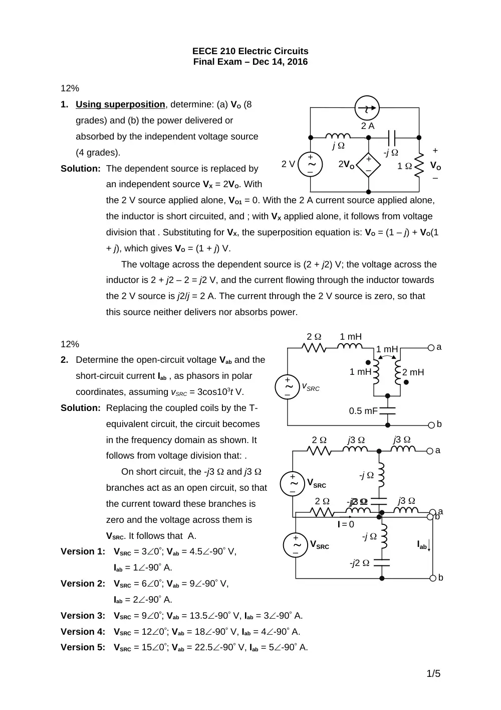
Solution: The dependent source is replaced by
an independent source VX = 2VO. With
the 2 V source applied alone, VO1 = 0. With the 2 A current source applied alone,
the inductor is short circuited, and ; with VX applied alone, it follows from voltage
division that . Substituting for VX, the superposition equation is: VO = (1 – j) + VO(1
+ j), which gives VO = (1 + j) V.
The voltage across the dependent source is (2 + j2) V; the voltage across the
inductor is 2 + j2 – 2 = j2 V, and the current flowing through the inductor towards
the 2 V source is j2/j = 2 A. The current through the 2 V source is zero, so that
this source neither delivers nor absorbs power.
12%
2.
Determine the open-circuit voltage Vab and the
short-circuit current Iab , as phasors in polar
coordinates, assuming vSRC = 3cos103t V.
Solution: Replacing the coupled coils by the T-
equivalent circuit, the circuit becomes
in the frequency domain as shown. It
follows from voltage division that: .
On short circuit, the -j3 and j3
branches act as an open circuit, so that
the current toward these branches is
zero and the voltage across them is
VSRC. It follows that A.
Version 1:
VSRC = 30; Vab = 4.5-90 V,
Iab = 1-90 A.
Version 2:
VSRC = 60; Vab = 9-90 V,
Iab = 2-90 A.
Version 3:
VSRC = 90; Vab = 13.5-90 V, Iab = 3-90 A.
Version 4:
VSRC = 120; Vab = 18-90 V, Iab = 4-90 A.
Version 5:
VSRC = 150; Vab = 22.5-90 V, Iab = 5-90 A.
1/5
1 mH
1 mH
2 mH
1 mH
2
0.5 mF
vSRC
–
+
a
b
-j
j3
2
-j2
VSRC
–
+
a
b
j3
Iab
I = 0
–
+
–
+
+
–
VO
1
-j
j
2 A
2 V
2VO
-j
j3
2
-j2
VSRC
–
+
a
b
j3
12%
3.
(a) Transform the 100 A source
and its source impedance to its
equivalent voltage source, and (b)
determine VO using the mesh-
current method, assuming ISRC =
10 A.
Solution: Mesh 1: I1 = ISRC;
Mesh 3: -j2I2 + (8 + j2)I3 = 0
For the dependent source,
IX = I3 = I2 – I1 = I2 – ISRC, so
that I2 = I3 + ISRC.
Substituting in the equation
for mesh 3:
-j2(I3 + ISRC) + (8 + j2)I3 = 0,
or, -j2ISRC + 8I3 = 0, or,
I3 = j0.25ISRC, so that VO =
8I3 = j2ISRC V.
Version 1:
ISRC = 10 A; VO = 290 V.
Version 2:
ISRC = 20 A; VO = 490 V.
Version 3:
ISRC = 30 A; VO = 690 V.
Version 4:
ISRC = 40 A; VO = 890 V.
Version 5:
ISRC = 50 A; VO = 1090 V.
13%
4.
Determine VS, assuming ISRC = 10 A.
Solution: From symmetry the –j20 reactance does not
carry current. It is redundant and can be
removed. Replacing the coupled coils by the T-
equivalent circuit, the circuit becomes as shown.
it follows that the impedance seen by the source
Is –j17.5 + j5 + j45/2 = j10 , so that VS = j10ISRC.
Alternatively, transforming the
delta to a star, and replacing the
coupled coils by the T-equivalent
circuit, the circuit becomes as shown.
It is seen that the impedance seen by
2/5
ISRC
4
100 A
- j 2
8
IX
IX
+
–
VO
j 2
ISRC
4
-j20 V
- j 2
8
IX
IX
+
–
VO
j 2
I1
I2
I3
–
+
ISRC
-j17.5
j15
j15
+
–
VS
j5
j30
j30
the source is -j17.5 + j5 + j22.5 = j10 . It follows that VS = j10ISRC.
Version 1:
ISRC = 10; VS = 1090 V.
Version 2:
ISRC = 1.50; VS = 1590 V.
Version 3:
ISRC = 20; VS = 2090 V.
Version 4:
ISRC = 2.50; VS = 2590 V.
Version 5:
ISRC = 30; VS = 3090 V.
13%
5.
Determine IL as a phasor in polar coordinates,
assuming vSRC(t) = cos(t + 45) V.
Solution: L = 22.5 , 1/C = 10 ; the circuit in the
frequency domain is as shown.
V1 = VSRC – j45IL; V2 = VSRC + j30IL;
2V1 + 3V2 = 10IL; substituting for V1 and
V2, 2VSRC – j90IL + 3VSRC + j90IL = 10IL;
IL = 0.5VSRC A
Version 1:
VSRC = 145; IL = 0.545 A.
Version 2:
VSRC = 245; IL = 145 A.
Version 3:
VSRC = 345; IL = 345 A.
Version 4:
VSRC = 445; IL = 245 A.
Version 5:
VSRC = 545; IL = 2.545 A.
12%
6.
The switch is closed at t = 0, with no stored energy in the
circuit. Determine iS(t), t 0+, assuming VSCR = 10 V.
Solution: The current flowing downwards in the capacitive
branch is A. The current flowing downwards in the
inductive branch is A, where C = 10×0.001= 0.01 s
and L = 0.1/10 = 0.01 s. It follows that iS(t) = VSRC/10
A.
3/5
+
–
10
10
0.1 H
1 mF
VSRC
iS
1:2
1:3
–
+
10
22.5 H
0.1 F
vSRC
iL
1:2
1:3
–
+
10
VSRC
IL
V1
_
+
2V1
_
+
V2
_
+
3V2
_
+
3IL
2IL
-j10
22.5
Version 1:
VSRC = 10, iS(t) = 10/10 = 1 A.
Version 2:
VSRC = 15, iS(t) = 15/10 = 1.5 A.
Version 3:
VSRC = 20, iS(t) = 20/10 = 2 A.
Version 4:
VSRC = 25, iS(t) = 25/10 = 2.5 A.
Version 5:
VSRC = 30, iS(t) = 30/10 = 3 A.
13%
7.
Both switches
are moved at
t = 0 after
being in their
initial
positions for a long time. Determine vC(t) and iL(t) for t 0+.
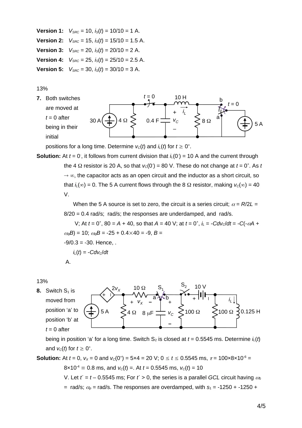
Solution: At t = 0-, it follows from current division that iL(0-) = 10 A and the current through
the 4 resistor is 20 A, so that vC(0-) = 80 V. These do not change at t = 0+. As t
, the capacitor acts as an open circuit and the inductor as a short circuit, so
that iL() = 0. The 5 A current flows through the 8 resistor, making vC() = 40
V.
When the 5 A source is set to zero, the circuit is a series circuit; = R/2L =
8/20 = 0.4 rad/s; rad/s; the responses are underdamped, and rad/s.
V; At t = 0+, 80 = A + 40, so that A = 40 V; at t = 0+, iL = -CdvC/dt = -C(-A +
dB) = 10; dB = -25 + 0.440 = -9, B =
-9/0.3 = -30. Hence, .
iL(t) = -CdvC/dt
A.
13%
8.
Switch S1 is
moved from
position ‘a’ to
position ‘b’ at
t = 0 after
being in position ‘a’ for a long time. Switch S2 is closed at t = 0.5545 ms. Determine iL(t)
and vC(t) for t 0+.
Solution: At t = 0, vX = 0 and vC(0+) = 5×4 = 20 V; 0 t 0.5545 ms, = 100×8×10-6 =
8×10⁻⁴ 0.8 ms, and vC(t) =. At t = 0.5545 ms, vC(t) = 10
V. Let t = t – 0.5545 ms; For t > 0, the series is a parallel GCL circuit having 0
= rad/s; p = rad/s. The responses are overdamped, with s1 = -1250 + -1250 +
4/5
–
+
+
–
vC
+
–
vX
2vX
8 F
100
100
0.125 H
a
b
S1
4
5 A
10
iL
+
–
10 V
S2
8
10 H
t = 0
0.4 F
4
30 A
iL
+
–
vC
t = 0
a
b
5 A
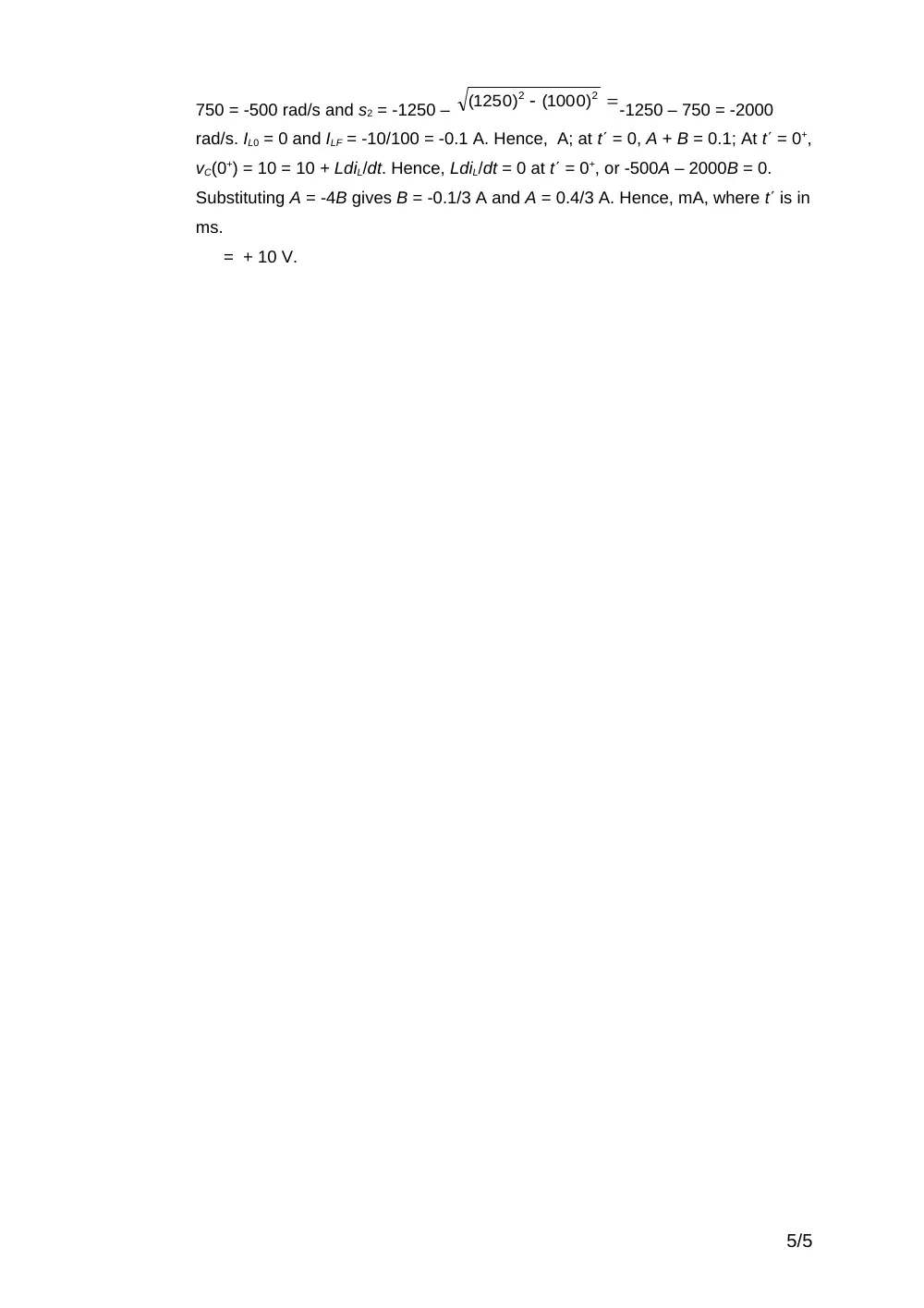
750 = -500 rad/s and s2 = -1250 –
-1250 – 750 = -2000
rad/s. IL0 = 0 and ILF = -10/100 = -0.1 A. Hence, A; at t = 0, A + B = 0.1; At t = 0+,
vC(0+) = 10 = 10 + LdiL/dt. Hence, LdiL/dt = 0 at t = 0+, or -500A – 2000B = 0.
Substituting A = -4B gives B = -0.1/3 A and A = 0.4/3 A. Hence, mA, where t is in
ms.
= + 10 V.
5/5
2
2
(1000)
(1250)