
EECE 210 Final, Fall 2010
American University of Beirut · Electric Circuits · 13 pages



Showing the first 10 of 13 pages. Download the PDF to see all of it.
More EECE 210 files
- Final · Fall 2018Final examView
- Final Exam-solution · Fall 2016Final exam · with solutionView
- Final · Spring 2016Final examView
- Final With Solution · Fall 2014Final exam · with solutionView
- Final · Fall 2013Final examView
- Problems For Final -with Some Solutions · Fall 2012Final exam · with solutionView
- Final with Solution · Fall 2011Final exam · with solutionView
- Final · Fall 2009Final examView
Show the text of this final exam
Final Exam – 2010-2011
3%
_
+
ISRC
5IX
15 Ω
12 Ω
5 Ω
IX
10 Ω
_
+
10 Ω
10 V
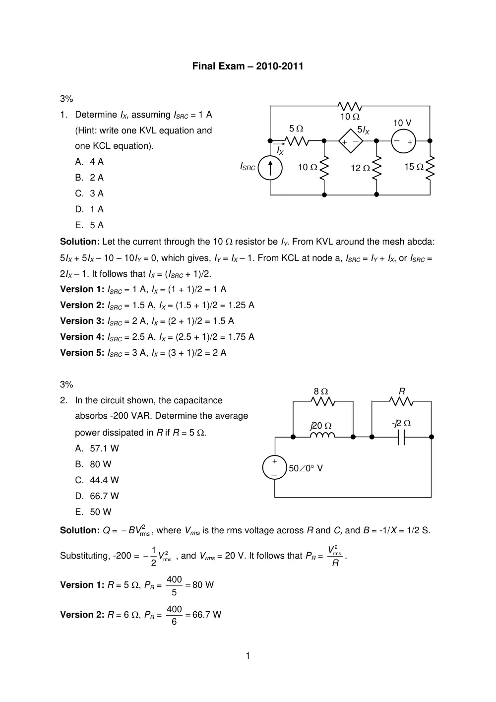
1. Determine IX, assuming ISRC = 1 A
(Hint: write one KVL equation and
one KCL equation).
A. 4 A
B. 2 A
C. 3 A
D. 1 A
E. 5 A
Solution: Let the current through the 10 Ω resistor be IY. From KVL around the mesh abcda:
5IX + 5IX – 10 – 10IY = 0, which gives, IY = IX – 1. From KCL at node a, ISRC = IY + IX, or ISRC =
2IX – 1. It follows that IX = (ISRC + 1)/2.
Version 1: ISRC = 1 A, IX = (1 + 1)/2 = 1 A
Version 2: ISRC = 1.5 A, IX = (1.5 + 1)/2 = 1.25 A
Version 3: ISRC = 2 A, IX = (2 + 1)/2 = 1.5 A
Version 4: ISRC = 2.5 A, IX = (2.5 + 1)/2 = 1.75 A
Version 5: ISRC = 3 A, IX = (3 + 1)/2 = 2 A
3%
8 Ω
j20 Ω
-j2 Ω
R
_
+
50∠0° V
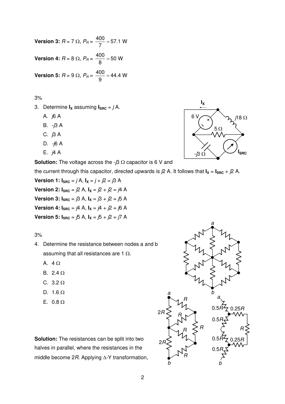
2. In the circuit shown, the capacitance
absorbs -200 VAR. Determine the average
power dissipated in R if R = 5 Ω.
A. 57.1 W
B. 80 W
C. 44.4 W
D. 66.7 W
E. 50 W
Solution: Q =
, where Vrms is the rms voltage across R and C, and B = -1/X = 1/2 S.
Substituting, -200 =
2
BVrms
−
2
2 rms
− 1V
, and Vrms = 20 V. It follows that PR = R
V
2
rms .
Version 1: R = 5 Ω, PR =
=
5
400
80 W
Version 2: R = 6 Ω, PR =
=
6
400
66.7 W
1
Version 3: R = 7 Ω, PR =
=
7
400
57.1 W
Version 4: R = 8 Ω, PR =
=
8
400
50 W
Version 5: R = 9 Ω, PR =
=
9
400
44.4 W
3%
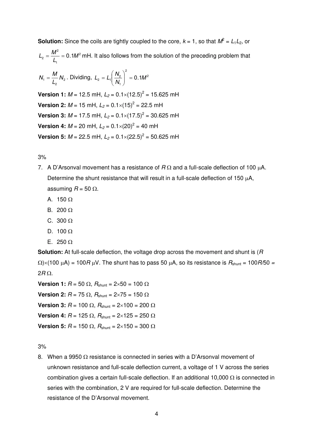
3. Determine IX assuming ISRC = j A.
A. j6 A
B. -j3 A
C. j3 A
D. -j6 A
E. j4 A
Solution: The voltage across the -j3 Ω capacitor is 6 V and
the current through this capacitor, directed upwards is j2 A. It follows that IX = ISRC + j2 A.
6 V
ISRC
j18 Ω
-j3 Ω
5 Ω
IX
Version 1: ISRC = j A, IX = j + j2 = j3 A
Version 2: ISRC = j2 A, IX = j2 + j2 = j4 A
Version 3: ISRC = j3 A, IX = j3 + j2 = j5 A
Version 4: ISRC = j4 A, IX = j4 + j2 = j6 A
Version 5: ISRC = j5 A, IX = j5 + j2 = j7 A
3%
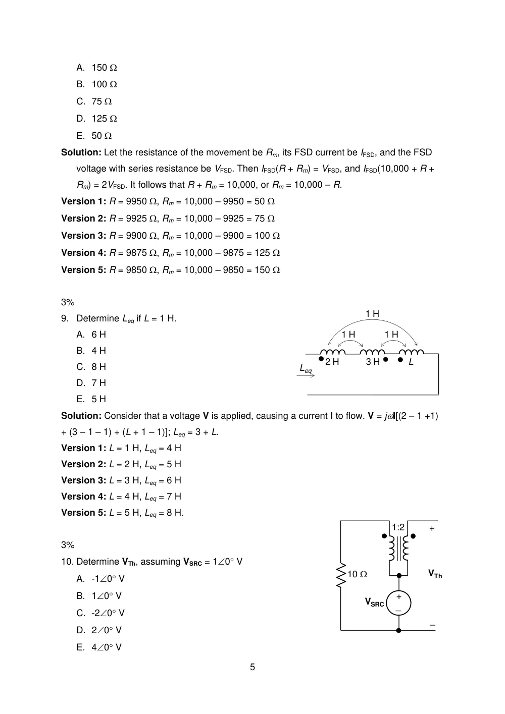
4. Determine the resistance between nodes a and b
assuming that all resistances are 1 Ω.
a
b
a
b
2R
2R
R
R
R
R
R
a
b
R
0.5R
0.5R
0.5R
0.5R
0.25R
0.25R
A. 4 Ω
B. 2.4 Ω
C. 3.2 Ω
D. 1.6 Ω
E. 0.8 Ω
Solution: The resistances can be split into two
halves in parallel, where the resistances in the
middle become 2R. Applying Δ-Y transformation,
2
the resistances become as shown. It follows that 2Rab = 0.5R + R||1.5R + 0.5R = R + 0.6R =
1.6R, so that Rab = 0.8R.
Version 1: R = 1 Ω, Rab = 0.8×1 = 0.8 Ω
Version 2: R = 2 Ω, Rab = 0.8×2 = 1.6 Ω
Version 3: R = 3 Ω, Rab = 0.8×3 = 2.4 Ω
Version 4: R = 4 Ω, Rab = 0.8×4 = 3.2 Ω
Version 5: R = 5 Ω, Rab = 0.8×5 = 4 Ω
3%
5. Two coils are tightly coupled to a high-permeability core, so that the leakage flux is
negligibly small. If coil 1 has 100 turns and an inductance of 10 mH, and the mutual
inductance is 12.5 mH, determine the number of turns of coil 2.
A. 125
B. 250
C. 150
D. 175
E. 200
Solution: From the definitions of self and mutual inductance, with negligible leakage flux,
1
21
1
1
i
N
L
φ
=
and
1
2 21
i
N
M
φ
=
. It follows that
M
L N
M
N
10
1
1
2
=
=
.
Version 1: M = 12.5 mH, N2 = 10×12.5 = 125 turns
Version 2: M = 15 mH, N2 = 10×15 = 150 turns
Version 3: M = 17.5 mH, N2 = 10×17.5 = 175 turns
Version 4: M = 20 mH, N2 = 10×20 = 200 turns
Version 5: M = 22.5 mH, N2 = 10×22.5 = 225 turns
3%
6. Determine the inductance of coil 2 of the preceding problem.
A. 22.5 mH
B. 30.63 mH
C. 15.63 mH
D. 40 mH
E. 50.63 mH
3
Solution: Since the coils are tightly coupled to the core, k = 1, so that M2 = L1L2, or
2
1
2
2
.1
0 M
L
M
L
=
=
mH. It also follows from the solution of the preceding problem that
2
2
1
L N
N = M
. Dividing,
2
2
1
2
1
2
.1
0 M
N
N
L
L
=
⎟⎟
⎠
⎞
⎜⎜
⎝
⎛
=
Version 1: M = 12.5 mH, L2 = 0.1×(12.5)2 = 15.625 mH
Version 2: M = 15 mH, L2 = 0.1×(15)2 = 22.5 mH
Version 3: M = 17.5 mH, L2 = 0.1×(17.5)2 = 30.625 mH
Version 4: M = 20 mH, L2 = 0.1×(20)2 = 40 mH
Version 5: M = 22.5 mH, L2 = 0.1×(22.5)2 = 50.625 mH
3%
7. A D’Arsonval movement has a resistance of R Ω and a full-scale deflection of 100 μA.
Determine the shunt resistance that will result in a full-scale deflection of 150 μA,
assuming R = 50 Ω.
A. 150 Ω
B. 200 Ω
C. 300 Ω
D. 100 Ω
E. 250 Ω
Solution: At full-scale deflection, the voltage drop across the movement and shunt is (R
Ω)×(100 μA) = 100R μV. The shunt has to pass 50 μA, so its resistance is Rshunt = 100R/50 =
2R Ω.
Version 1: R = 50 Ω, Rshunt = 2×50 = 100 Ω
Version 2: R = 75 Ω, Rshunt = 2×75 = 150 Ω
Version 3: R = 100 Ω, Rshunt = 2×100 = 200 Ω
Version 4: R = 125 Ω, Rshunt = 2×125 = 250 Ω
Version 5: R = 150 Ω, Rshunt = 2×150 = 300 Ω
3%
8. When a 9950 Ω resistance is connected in series with a D’Arsonval movement of
unknown resistance and full-scale deflection current, a voltage of 1 V across the series
combination gives a certain full-scale deflection. If an additional 10,000 Ω is connected in
series with the combination, 2 V are required for full-scale deflection. Determine the
resistance of the D’Arsonval movement.
4
A. 150 Ω
B. 100 Ω
C. 75 Ω
D. 125 Ω
E. 50 Ω
Solution: Let the resistance of the movement be Rm, its FSD current be IFSD, and the FSD
voltage with series resistance be VFSD. Then IFSD(R + Rm) = VFSD, and IFSD(10,000 + R +
Rm) = 2VFSD. It follows that R + Rm = 10,000, or Rm = 10,000 – R.
Version 1: R = 9950 Ω, Rm = 10,000 – 9950 = 50 Ω
Version 2: R = 9925 Ω, Rm = 10,000 – 9925 = 75 Ω
Version 3: R = 9900 Ω, Rm = 10,000 – 9900 = 100 Ω
Version 4: R = 9875 Ω, Rm = 10,000 – 9875 = 125 Ω
Version 5: R = 9850 Ω, Rm = 10,000 – 9850 = 150 Ω
3%
2 H
Leq
3 H
L
1 H
1 H
1 H
9. Determine Leq if L = 1 H.
A. 6 H
B. 4 H
C. 8 H
D. 7 H
E. 5 H
Solution: Consider that a voltage V is applied, causing a current I to flow. V = jωI[(2 – 1 +1)
+ (3 – 1 – 1) + (L + 1 – 1)]; Leq = 3 + L.
Version 1: L = 1 H, Leq = 4 H
Version 2: L = 2 H, Leq = 5 H
Version 3: L = 3 H, Leq = 6 H
Version 4: L = 4 H, Leq = 7 H
Version 5: L = 5 H, Leq = 8 H.
10 Ω
_
+
VSRC
–
+
VTh
1:2
3%
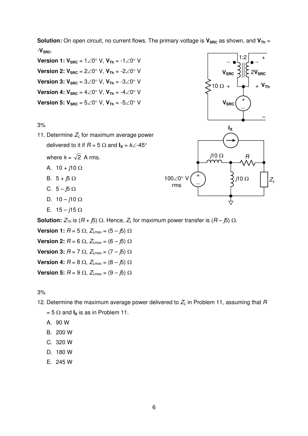
10. Determine VTh, assuming VSRC = 1∠0° V
A. -1∠0° V
B. 1∠0° V
C. -2∠0° V
D. 2∠0° V
E. 4∠0° V
5
Solution: On open circuit, no current flows. The primary voltage is VSRC as shown, and VTh =
-VSRC.
10 Ω
_
+
VSRC
–
+
VTh
1:2
_
+
VSRC
_
+
2VSRC
Version 1: VSRC = 1∠0° V, VTh = -1∠0° V
Version 2: VSRC = 2∠0° V, VTh = -2∠0° V
Version 3: VSRC = 3∠0° V, VTh = -3∠0° V
Version 4: VSRC = 4∠0° V, VTh = -4∠0° V
Version 5: VSRC = 5∠0° V, VTh = -5∠0° V
3%
R
_
+
100∠0° V
rms
IX
j10 Ω
j10 Ω
ZL
11. Determine ZL for maximum average power
delivered to it if R = 5 Ω and IX = k∠-45°
where k =
2 A rms.
A. 10 + j10 Ω
B. 5 + j5 Ω
C. 5 – j5 Ω
D. 10 – j10 Ω
E. 15 – j15 Ω
Solution: ZTh is (R + j5) Ω. Hence, ZL for maximum power transfer is (R – j5) Ω.
Version 1: R = 5 Ω, ZLmax = (5 – j5) Ω
Version 2: R = 6 Ω, ZLmax = (6 – j5) Ω
Version 3: R = 7 Ω, ZLmax = (7 – j5) Ω
Version 4: R = 8 Ω, ZLmax = (8 – j5) Ω
Version 5: R = 9 Ω, ZLmax = (9 – j5) Ω
3%
12. Determine the maximum average power delivered to ZL in Problem 11, assuming that R
= 5 Ω and IX is as in Problem 11.
A. 90 W
B. 200 W
C. 320 W
D. 180 W
E. 245 W
6
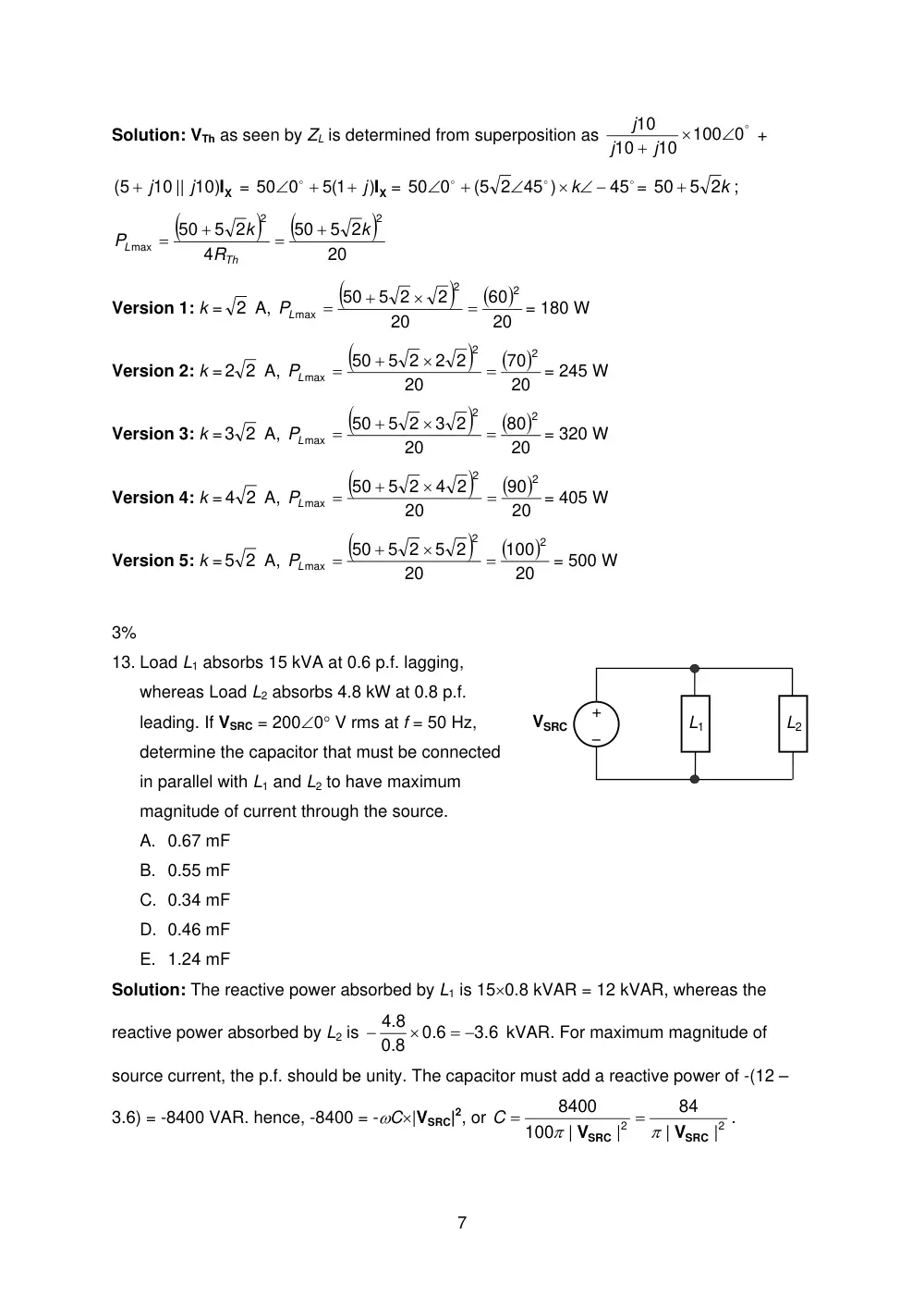
Solution: VTh as seen by ZL is determined from superposition as
∠ °
×
+
100 0
10
10
10
j
j
j
+
=
=
10 || 10 XI)
(5
j
+ j
XI)
5(1
50 0
+ j
+
∠
o
o
o
o
45
(5 2 45 )
50 0
× ∠ −
∠
+
∠
k
=
50 + 5 2k
;
(
)
(
)
20
5 2
50
2
2
k
k
+
=
4
5 2
50
max
R
P
Th
L
+
=
Version 1: k =
2 A,
(
)
(
)
20
60
20
2
5 2
50
2
2
max
=
×
+
=
PL
= 180 W
Version 2: k =
2 2
A,
(
)
(
)
20
70
20
2 2
5 2
50
2
2
max
=
×
+
=
PL
= 245 W
Version 3: k =
3 2
A,
(
)
(
)
20
80
20
3 2
5 2
50
2
2
max
=
×
+
=
PL
= 320 W
Version 4: k =
4 2
A,
(
)
(
)
20
90
20
4 2
5 2
50
2
2
max
=
×
+
=
PL
= 405 W
Version 5: k =
5 2
A,
(
)
(
)
20
100
20
5 2
5 2
50
2
2
max
=
×
+
=
PL
= 500 W
3%
13. Load L1 absorbs 15 kVA at 0.6 p.f. lagging,
whereas Load L2 absorbs 4.8 kW at 0.8 p.f.
leading. If VSRC = 200∠0° V rms at f = 50 Hz,
determine the capacitor that must be connected
in parallel with L1 and L2 to have maximum
magnitude of current through the source.
–
+
L1
L2
VSRC
A. 0.67 mF
B. 0.55 mF
C. 0.34 mF
D. 0.46 mF
E. 1.24 mF
Solution: The reactive power absorbed by L1 is 15×0.8 kVAR = 12 kVAR, whereas the
reactive power absorbed by L2 is
3.6
0.6
0.8
4.8
= −
×
−
kVAR. For maximum magnitude of
source current, the p.f. should be unity. The capacitor must add a reactive power of -(12 –
3.6) = -8400 VAR. hence, -8400 = -ωC×|VSRC|2, or
2
2
|
|
84
|
|
100
8400
SRC
SRC
V
V
π
π
=
C =
.
7
Version 1: |VSRC| = 200 V,
0.67
(200)
84
2 ≡
=
π
C
mF
Version 2: |VSRC| = 220 V,
0.55
(220)
84
2 ≡
=
π
C
mF
Version 3: |VSRC| = 240 V,
0.46
(240)
84
2 ≡
=
π
C
mF
Version 4: |VSRC| = 260 V,
0.40
(200)
84
2 ≡
=
π
C
mF
Version 5: |VSRC| = 280 V,
0.34
(200)
84
2 ≡
=
π
C
mF
3%
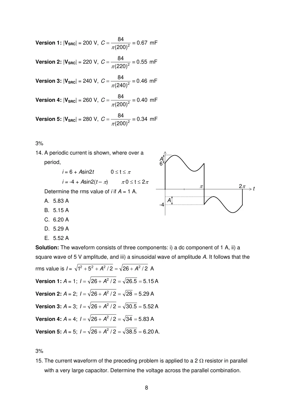
14. A periodic current is shown, where over a
period,
t
π
6
A
2π
-4
A
i = 6 + Asin2t
0 ≤ t ≤ π
i = -4 + Asin2(t – π)
π 0 ≤ t ≤ 2π
Determine the rms value of i if A = 1 A.
A. 5.83 A
B. 5.15 A
C. 6.20 A
D. 5.29 A
E. 5.52 A
Solution: The waveform consists of three components: i) a dc component of 1 A, ii) a
square wave of 5 V amplitude, and iii) a sinusoidal wave of amplitude A. It follows that the
rms value is I =
/ 2
26
/ 2
5
1
2
2
2
2
A
A
+
=
+
+
A
Version 1: A = 1;
5.15
26.5
/ 2
26
2
=
=
+
=
A
I
A
Version 2: A = 2;
5.29
28
/ 2
26
2
=
=
+
=
A
I
A
Version 3: A = 3;
5.52
30.5
/ 2
26
2
=
=
+
=
A
I
A
Version 4: A = 4;
5.83
34
/ 2
26
2
=
=
+
=
A
I
A
Version 5: A = 5;
6.20
38.5
/ 2
26
2
=
=
+
=
A
I
A.
3%
15. The current waveform of the preceding problem is applied to a 2 Ω resistor in parallel
with a very large capacitor. Determine the voltage across the parallel combination.
8
A. 2.5 V
B. 2 V
C. 3 V
D. 4 V
E. 3.5 V
Solution: The ac voltage will be negligibly small. The dc voltage is the dc component of
current multiplied by R, or V = 1×R.
Version 1: R = 2 Ω; V = R = 2 V
Version 2: R = 2.5 Ω; V = R = 2.5 V
Version 3: R = 3 Ω; V = R = 3 V
Version 4: R = 3.5 Ω; V = R = 3.5 V
Version 5: R = 4 Ω; V = R = 4 V
11%
16. The period of a periodic function f(t) is defined as:
f(t) = cos(t + π) – 2,
-π < t < -π/2
f(t) = -cos(t) + k,
-π/2 < t < +π/2
f(t) = cos(t – π) – 2,
π/2 < t < π
Derive the trigonometric Fourier series expansion of
f(t), assuming k = 3.
Solution:
(
)
⎥⎦
⎤
⎢⎣
⎡
−
−
+
+
−
=
∫
∫
π
π
π
π
π
2
/
2
/
0
2
)
cos(
)
( cos
1
dt
t
k dt
t
ao
=
⎥⎦
⎤
⎢⎣
⎡
−
−
−
∫
∫
∫
∫
2
/
0
/ 2
2
/
2
/
0
cos
cos
2
1
π
π
π
π
π
π
π
tdt
tdt
dt
k dt
=
⎥⎦
⎤
⎢⎣
⎡
− ∫
∫
π
π
π
π
2
/
2
/
0
2
1
dt
k dt
=
⎥⎦
⎤
⎢⎣
⎡
π − π
π
2
1 k
=
2 −1
k
.
f(t)
t
π
1
π /2
-π
-π/2
k
-1
-2
an =
(
)
⎥⎦
⎤
⎢⎣
⎡
−
−
+
+
−
∫
∫
π
π
π
π
π
2
/
2
/
0
2 cos
)
cos(
)cos
( cos
2
ntdt
t
ntdt
k
t
=
⎥⎦
⎤
⎢⎣
⎡
−
+
−
∫
∫
∫
π
π
π
π
π
2
/
2
/
0
0
2cos
cos
cos cos
2
ntdt
ntdt
k
ntdt
t
=
⎥⎦
⎤
⎢⎣
⎡
−
+
+
−
−
−
∫
∫
∫
∫
π
π
π
π
π
π
2
/
2
/
0
0
0
2 cos
cos
)1
cos(
2
1
)1
cos(
2
1
2
ntdt
ntdt
k
tdt
n
tdt
n
=
[
]
[
]
π
π
π
π
π
π
π
/ 2
/ 2
0
0
sin
4
sin
2
1
)1
sin(
1
)1
1 sin(
nt
n
nt
n
k
n
t
n
n
t
n
−
+
⎥⎦
⎤
⎢⎣
⎡
+
+
+
−
−
−
=
4 sin 2
0
0
sin 2
2
0
0
π
π
π
π
n
n
n
n
k
+
−
−
+
−
=
2) sin 2
2(
π
π
n
n
k +
. an is zero for even values, and the
9
odd harmonics alternate in sign. Thus,
⎟
⎠
⎞
⎜
⎝
⎛
+
−
+
−
+
+
⎟
⎠
⎞
⎜
⎝
⎛
−
=
...
7 cos7
1
5 cos5
1
3 cos3
1
2) cos
2(
2
1 1
2
( )
t
t
t
t
k
k
f t
π
Version 1: k = 3,
⎟
⎠
⎞
⎜
⎝
⎛
+
−
+
−
+
=
...
7 cos7
1
5 cos5
1
3 cos3
1
10 cos
2
1
( )
t
t
t
t
f t
π
Version 2: k = 4,
⎟
⎠
⎞
⎜
⎝
⎛
+
−
+
−
+
=
...
7 cos7
1
5 cos5
1
3 cos3
1
12 cos
1
( )
t
t
t
t
f t
π
Version 3: k = 5,
⎟
⎠
⎞
⎜
⎝
⎛
+
−
+
−
+
=
...
7 cos7
1
5 cos5
1
3 cos3
1
14 cos
2
3
( )
t
t
t
t
f t
π
Version 4: k = 6,
⎟
⎠
⎞
⎜
⎝
⎛
+
−
+
−
+
=
...
7 cos7
1
5 cos5
1
3 cos3
1
16 cos
2
( )
t
t
t
t
f t
π
Version 5: k = 7,
⎟
⎠
⎞
⎜
⎝
⎛
+
−
+
−
+
=
...
7 cos7
1
5 cos5
1
3 cos3
1
18 cos
2
5
( )
t
t
t
t
f t
π
11%
_
+
vSRC
iX
1 H
iSRC
1 F
1 Ω
17. Given vSRC = cost V and iSRC = sin2t A.
6% (a) Derive the expression for iX in the time
domain.
5% (b) Determine the power dissipated in the
resistor.
Solution: (a) Let the amplitude of vSRC and iSRC be K. With the current source replaced by an
open circuit, Ix1 =
=
+
∠
j
K
1
1
1
0
o
)
2 (1
j
K
−
; iX1 =
45 )
cos(
2
o
t −
K
A. With the current source
replaced by a short circuit, Ix2 =
=
+
∠
2
1
2
0
j
j
K
o
2)
tan
(90
5
2
−1
−
∠
o
K
; iX2 =
26.57 )
sin(2
5
2
o
t +
K
A. Hence, iX =
45 )
cos(
2
o
t −
K
+
26.57 )
sin(2
5
2
o
t +
K
A.
(b) Power dissipated is P =
2
2
2
0.65
5
4
2
2
1
K
K
K
⎟⎟ =
⎠
⎞
⎜⎜
⎝
⎛
+
W.
Version 1: K = 1,
+
A, P = 0.65 W
45 )
0.71cos(
o
t −
26.57 )
0.89sin(2
o
+
t
Version 2: K = 2,
+
A, P = 2.60 W
45 )
1.14cos(
o
t −
26.57 )
1.79sin(2
o
+
t
Version 3: K = 3,
+
A, P = 5.85 W
45 )
2.12cos(
o
t −
26.57 )
2.68sin(2
o
+
t
Version 4: K = 4,
+
A, P = 10.4 W
45 )
2.83cos(
o
t −
26.57 )
3.58sin(2
o
+
t
Version 5: K = 5,
+
A, P = 16.25 W
45 )
3.54cos(
o
t −
26.57 )
4.47sin(2
o
+
t
10
11%
18. Given the circuit shown, with a = 1.
–
+
5∠0° V
-j Ω
1:a
ISRC
3% (a) Determine the current in the capacitor
2% (b) Replace the capacitor by a current
source, in accordance with the
substitution theorem
3% (c) Rearrange the current source as two
current sources across the transformer
windings
3% (d) Determine ISRC.
Solution: (a) The voltage across the capacitor is 5(1 + a) V. The current through the
capacitor is j5(1 + a) A directed from primary to secondary.
(b)
(c)
–
+
5∠0° V
j5(1 + a) A
1:a
j5a(1 + a) A
1:a
j5(1 + a) A
j5(1 + a) A
ISRC
(d) It follows that ISRC = j5(a + 1)2 A.
Version 1: a = 2, ISRC = j5(2 + 1)2 = j45 A
Version 2: a = 3, ISRC = j5(3 + 1)2 = j80 A
Version 3: a = 4, ISRC = j5(4 + 1)2 = j125 A
Version 4: a = 5, ISRC = j5(5 + 1)2 = j180 A
Version 5: a = 6, ISRC = j5(6 + 1)2 = j245 A
11%
j5 Ω
5 Ω
19. Determine X and R for maximum power
transfer to R and calculate this power.
Assume VSRC = 4∠0° V rms.
1:2
–
+
1:3
jX
R
VSRC
11
Solution: On open circuit, VTH = V = VSRC. On
short circuit, V = 0 and IN = I =
)
5(1
j
+
VSRC
. YN =
)
5(1
1
+ j
= 0.1(1 – j) S. For maximum power
transfer, GL = 0.1 S, or R = 10 Ω, and B = 0.1 S,
or X = -10 Ω.
5 Ω
–
+
j5 Ω
1:2
1:3
VSRC
–
+
V
–
V
+
–
+
2V
–
+
3V
–
+
VTh
Under conditions of maximum power
transfer, the current in R is 0.5|IN| =
10
|
0 5 |
VSRC
.
and the power transferred is
10
|
0 25 |
VSRC 2
.
=
40
|
|
VSRC 2
W.
5 Ω
j5 Ω
–
+
1:2
VSRC
I
2I
1:3
3I
–
+
V
–
V
+
+
2V
–
+
3V
–
I
Version 1: VSRC = 4∠0° rms, P =
0.4
40
16 =
W
Version 2: VSRC = 5∠0° rms, P =
0.625
40
25 =
W
Version 3: VSRC = 6∠0° rms, P =
0.9
40
36 =
W
Version 4: VSRC = 7∠0° rms, P =
1.225
40
49 =
W
Version 5: VSRC = 8∠0° rms, P =
1.6
40
64 =
W.
11%
200
turns
100
turns
ZL
_
+
VSRC
ISRC
20. Determine the complex power delivered by each
source given that VSRC = 5cosωt, ISRC = -2sinωt,
and assuming ZL = k(1 – j) where k = 1.
Solution: The currents and voltages are as shown.
Equating mmfs: 100×2∠90° + 200IL = 0, or j2 = -2IL,
and IL =-j A, I1 = IL – j2 = -j3 A.
VL = ZLIL = -jk(1 – j) = -k(1 + j) V. V2 = VL – 5 = -(k +
5) – jk. V1 = V2/2 = -(k + 5)/2 – jk/2 V. VI = 5 – V1 =
(15 + k)/2 + jk/2 V.
Power delivered by voltage source = Sv =
( )
2
15
2 5 ( 3)
1
2
2
1
j
j
Vsrc I
=
=
∗
VA
12
Power delivered by current source SI =
=
⎟ −
⎠
⎞
⎜
⎝
⎛
+
+
=
∗
2)
2 (
2
15
2
1
2
I
2
V
SRC
I
j
jk
k
(
))
(15
2
1
k
j
k
+
−
VA
I1
–
+
V1
–
+
VL
IL
200
turns
100
turns
ZL
_
+
–
+
V2
–
+
VI
j2 A
5 V
Total power delivered by sources =
(
)
(
)j
k
jk
j
k
j
−
=
−
−
+
2 1
)
15
15
2
1
As a check, SL =
(
)
(
j
k
j
j
jk
I
V
Lm
Lm
−
=
−
−
=
∗
2 1
) ( )
(1
2
1
2
2
) VA.
Version 1: k = 1, Sv = j7.5 VA; SI = 0.5 – j8 VA
Version 2: k = 2, Sv = j7.5 VA; SI = 1 – j8.5 VA
Version 3: k = 3, Sv = j7.5 VA; SI = 1.5 – j9 VA
Version 4: k = 4, Sv = j7.5 VA; SI = 2 – j9.5 VA
Version 5: k = 5, Sv = j7.5 VA; SI = 2.5 – j10 VA
13