
EECE 210 Final, Fall 2013
American University of Beirut · Electric Circuits · 10 pages


More EECE 210 files
- Final · Fall 2018Final examView
- Final Exam-solution · Fall 2016Final exam · with solutionView
- Final · Spring 2016Final examView
- Final With Solution · Fall 2014Final exam · with solutionView
- Problems For Final -with Some Solutions · Fall 2012Final exam · with solutionView
- Final with Solution · Fall 2011Final exam · with solutionView
- Final · Fall 2010Final examView
- Final · Fall 2009Final examView
Show the text of this final exam
EECE 210
Final Exam, December 18, 2013
3% (Primal Question)
A. The switch is closed at t = 0, with the capacitor initially charged
to 5 V in the polarity of vC. Derive the expression for vC as a
function of time for t 0.
Solution: The initial value of vC is 5 V. It final value is zero. = RC
= 0.5 s. It follows that
V.
Version 1: VC0 = 5 V,
V
Version 2: VC0 = 10 V,
V
Version 3: VC0 = 15 V,
V
Version 4: VC0 = 20 V,
V
Version 5: VC0 = 25 V,
V.
3% (Primal Question)
B. The switch is closed at t = 0, with the inductor initially
uncharged. Derive the expression for i as a function of
time for t 0, given VSRC = 1 V.
Solution: The initial value of i is zero, and the final value is
2 A. = L/R = 2 s. It follows that
A.
Version 1: VSRC = 1 V,
A
Version 2: VSRC = 2 V,
A
Version 3: VSRC = 3 V,
A
Version 4: VSRC = 4 V,
A
Version 5: VSRC = 5 V,
A.
3% (Primal Question)
C. When the switch is closed at t = 0, the initial voltage across
the capacitor is 10 V and the initial current through the
inductor is 1 A. Determine the values of vC and iL just after
the switch is closed, given R = 2 .
Solution: The values of vC and iL remain the same just after switching as just before
1
+
–
0.5
1 H
i
VSRC
t = 0
R
1 H
iL
t = 0
–
vC
+
0.25 F
0.5 F
t = 0
1
+
–
vC
switching.
Version 1: VC0 = 10 V, IL0 = 1 A
Version 2: VC0 = 15 V, IL0 = 2 A
Version 3: VC0 = 20 V, IL0 = 3 A
Version 4: VC0 = 25 V, IL0 = 4 A
Version 5: VC0 = 30 V, IL0 = 5 A.
3% (Primal Question)
D. Specify whether the response for t 0 in the preceding problem is overdamped, critically
damped, or underdamped if R = 2 .
Solution:
rad/s. = R/2L = R/2. The response is critically
damped if R = 4 , is overdamped if R > 4 , and is underdamped if R < 4 .
Version 1: R = 2 , response is underdamped
Version 2: R = 3 , response is underdamped
Version 3: R = 4 , response is critically damped
Version 4: R = 5 , response is overdamped
Version 5: R = 6 , response is overdamped.
3%
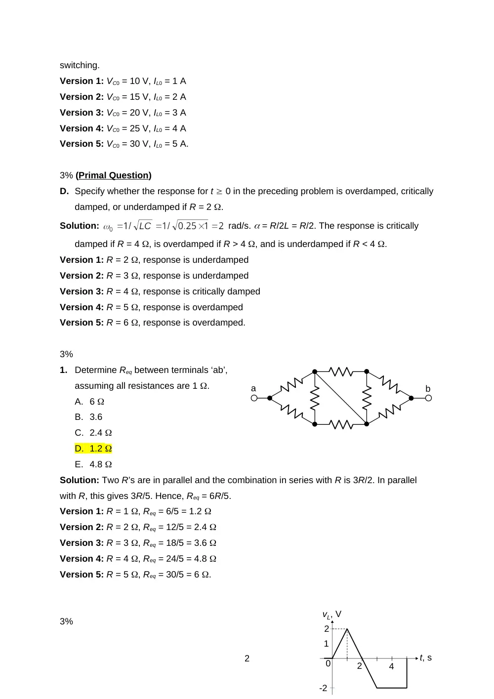
1.
Determine Req between terminals ‘ab’,
assuming all resistances are 1 .
A. 6
B. 3.6
C. 2.4
D. 1.2
E. 4.8
Solution: Two R’s are in parallel and the combination in series with R is 3R/2. In parallel
with R, this gives 3R/5. Hence, Req = 6R/5.
Version 1: R = 1 , Req = 6/5 = 1.2
Version 2: R = 2 , Req = 12/5 = 2.4
Version 3: R = 3 , Req = 18/5 = 3.6
Version 4: R = 4 , Req = 24/5 = 4.8
Version 5: R = 5 , Req = 30/5 = 6 .
3%
2
a
b
vL, V
1
2
0
t, s
-2
2
4
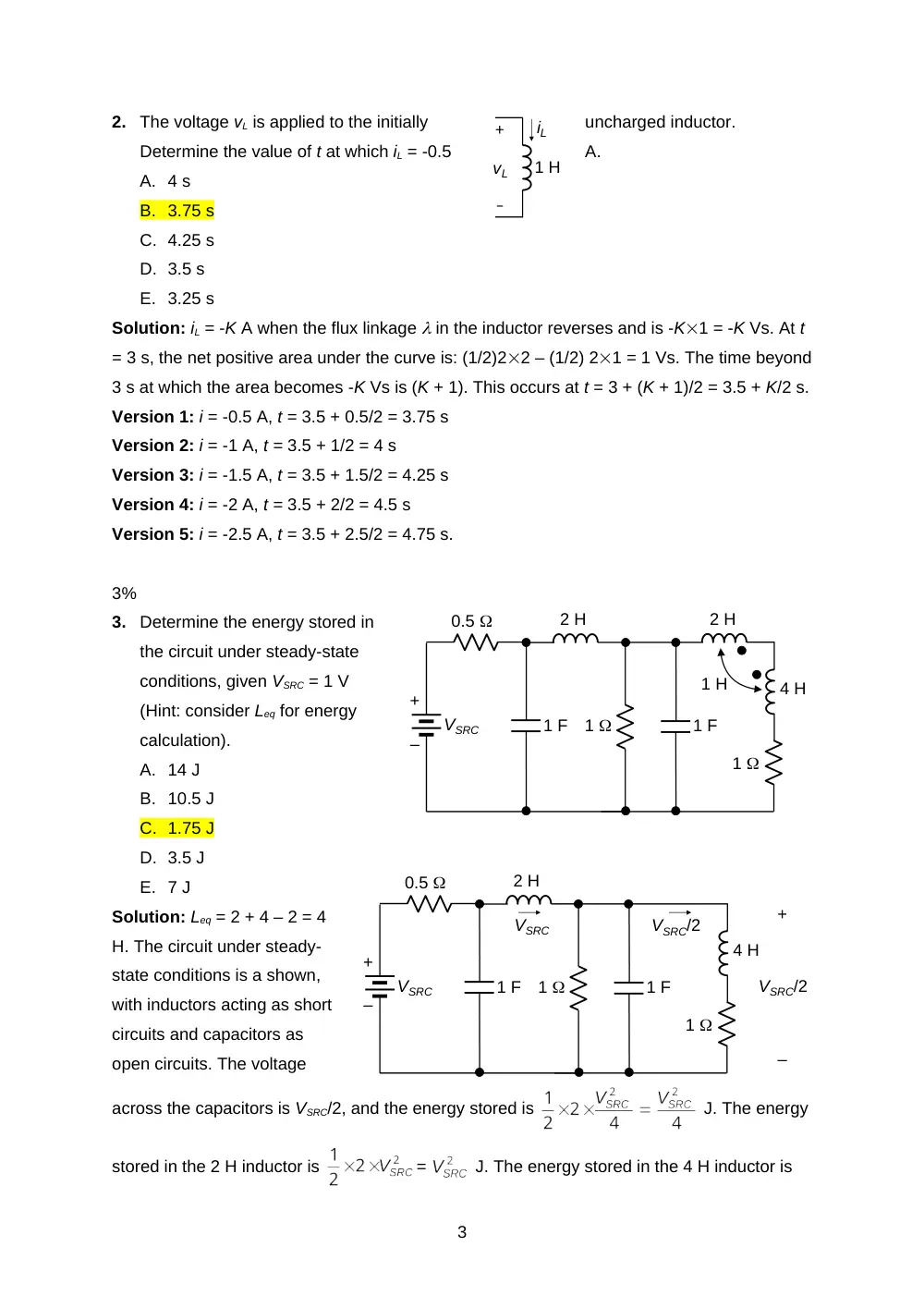
2.
The voltage vL is applied to the initially
uncharged inductor.
Determine the value of t at which iL = -0.5
A.
A. 4 s
B. 3.75 s
C. 4.25 s
D. 3.5 s
E. 3.25 s
Solution: iL = -K A when the flux linkage in the inductor reverses and is -K1 = -K Vs. At t
= 3 s, the net positive area under the curve is: (1/2)22 – (1/2) 21 = 1 Vs. The time beyond
3 s at which the area becomes -K Vs is (K + 1). This occurs at t = 3 + (K + 1)/2 = 3.5 + K/2 s.
Version 1: i = -0.5 A, t = 3.5 + 0.5/2 = 3.75 s
Version 2: i = -1 A, t = 3.5 + 1/2 = 4 s
Version 3: i = -1.5 A, t = 3.5 + 1.5/2 = 4.25 s
Version 4: i = -2 A, t = 3.5 + 2/2 = 4.5 s
Version 5: i = -2.5 A, t = 3.5 + 2.5/2 = 4.75 s.
3%
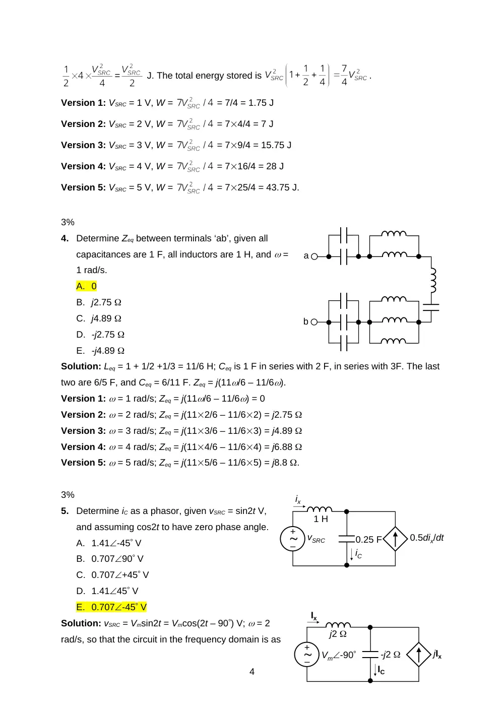
3.
Determine the energy stored in
the circuit under steady-state
conditions, given VSRC = 1 V
(Hint: consider Leq for energy
calculation).
A. 14 J
B. 10.5 J
C. 1.75 J
D. 3.5 J
E. 7 J
Solution: Leq = 2 + 4 – 2 = 4
H. The circuit under steady-
state conditions is a shown,
with inductors acting as short
circuits and capacitors as
open circuits. The voltage
across the capacitors is VSRC/2, and the energy stored is
J. The energy
stored in the 2 H inductor is
=
J. The energy stored in the 4 H inductor is
3
4 H
1 H
2 H
+
–
VSRC
1 F
1 F
1
1
2 H
0.5
+
–
vL
iL
1 H
4 H
+
–
VSRC
1 F
1 F
1
1
2 H
0.5
VSRC
VSRC/2
+
–
VSRC/2
=
J. The total energy stored is
.
Version 1: VSRC = 1 V, W =
= 7/4 = 1.75 J
Version 2: VSRC = 2 V, W =
= 74/4 = 7 J
Version 3: VSRC = 3 V, W =
= 79/4 = 15.75 J
Version 4: VSRC = 4 V, W =
= 716/4 = 28 J
Version 5: VSRC = 5 V, W =
= 725/4 = 43.75 J.
3%
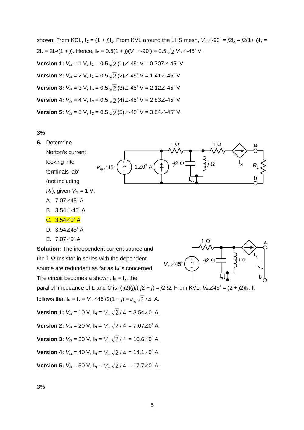
4.
Determine Zeq between terminals ‘ab’, given all
capacitances are 1 F, all inductors are 1 H, and =
1 rad/s.
A. 0
B. j2.75
C. j4.89
D. -j2.75
E. -j4.89
Solution: Leq = 1 + 1/2 +1/3 = 11/6 H; Ceq is 1 F in series with 2 F, in series with 3F. The last
two are 6/5 F, and Ceq = 6/11 F. Zeq = j(11/6 – 11/6).
Version 1: = 1 rad/s; Zeq = j(11/6 – 11/6) = 0
Version 2: = 2 rad/s; Zeq = j(112/6 – 11/62) = j2.75
Version 3: = 3 rad/s; Zeq = j(113/6 – 11/63) = j4.89
Version 4: = 4 rad/s; Zeq = j(114/6 – 11/64) = j6.88
Version 5: = 5 rad/s; Zeq = j(115/6 – 11/65) = j8.8 .
3%
5.
Determine iC as a phasor, given vSRC = sin2t V,
and assuming cos2t to have zero phase angle.
A. 1.41-45 V
B. 0.70790 V
C. 0.707+45 V
D. 1.4145 V
E. 0.707-45 V
Solution: vSRC = Vmsin2t = Vmcos(2t – 90) V; = 2
rad/s, so that the circuit in the frequency domain is as
4
–
+
vSRC
1 H
0.25 F
ix
0.5dix/dt
iC
–
+
Vm-90
j2
Ix
jIx
IC
-j2
a
b
shown. From KCL, IC = (1 + j)Ix. From KVL around the LHS mesh, Vm-90 = j2Ix – j2(1+ j)Ix =
2Ix = 2IC/(1 + j). Hence, IC = 0.5(1 + j)(Vm-90) = 0.5
Vm-45 V.
Version 1: Vm = 1 V, IC = 0.5
(1)-45 V = 0.707-45 V
Version 2: Vm = 2 V, IC = 0.5
(2)-45 V = 1.41-45 V
Version 3: Vm = 3 V, IC = 0.5
(3)-45 V = 2.12-45 V
Version 4: Vm = 4 V, IC = 0.5
(4)-45 V = 2.83-45 V
Version 5: Vm = 5 V, IC = 0.5
(5)-45 V = 3.54-45 V.
3%
6.
Determine
Norton’s current
looking into
terminals ‘ab’
(not including
RL), given Vm = 1 V.
A. 7.0745 A
B. 3.54-45 A
C. 3.540 A
D. 3.5445 A
E. 7.070 A
Solution: The independent current source and
the 1 resistor in series with the dependent
source are redundant as far as IN is concerned.
The circuit becomes a shown. IN = Ix; the
parallel impedance of L and C is; (-j2)(j)/(-j2 + j) = j2 . From KVL, Vm45 = (2 + j2)Ix. It
follows that IN = Ix = Vm45/2(1 + j) =
A.
Version 1: Vm = 10 V, IN =
= 3.540 A
Version 2: Vm = 20 V, IN =
= 7.070 A
Version 3: Vm = 30 V, IN =
= 10.60 A
Version 4: Vm = 40 V, IN =
= 14.10 A
Version 5: Vm = 50 V, IN =
= 17.70 A.
3%
5
–
+
10 A
Vm45
-j2
j
Ix
1
1
a
b
RL
Ix
–
+
Vm45
-j2
j
Ix
1
a
b
Ix
IN
7.
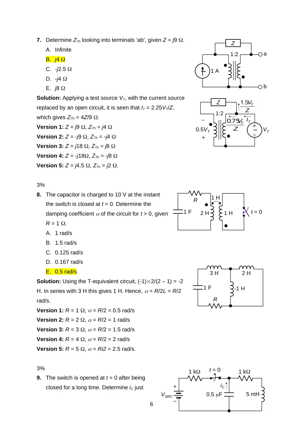
Determine ZTh looking into terminals ‘ab’, given Z = j9 .
A. Infinite
B. j4
C. -j2.5
D. -j4
E. j8
Solution: Applying a test source VT, with the current source
replaced by an open circuit, it is seen that IT = 2.25VT/Z,
which gives ZTh = 4Z/9 .
Version 1: Z = j9 , ZTh = j4
Version 2: Z = -j9 , ZTh = -j4
Version 3: Z = j18 , ZTh = j8
Version 4: Z = -j18, ZTh = -j8
Version 5: Z = j4.5 , ZTh = j2 .
3%
8.
The capacitor is charged to 10 V at the instant
the switch is closed at t = 0. Determine the
damping coefficient of the circuit for t > 0, given
R = 1 .
A. 1 rad/s
B. 1.5 rad/s
C. 0.125 rad/s
D. 0.167 rad/s
E. 0.5 rad/s
Solution: Using the T-equivalent circuit, (-1)2/(2 – 1) = -2
H. In series with 3 H this gives 1 H. Hence, = R/2L = R/2
rad/s.
Version 1: R = 1 , = R/2 = 0.5 rad/s
Version 2: R = 2 , = R/2 = 1 rad/s
Version 3: R = 3 , = R/2 = 1.5 rad/s
Version 4: R = 4 , = R/2 = 2 rad/s
Version 5: R = 5 , = Ri2 = 2.5 rad/s.
3%
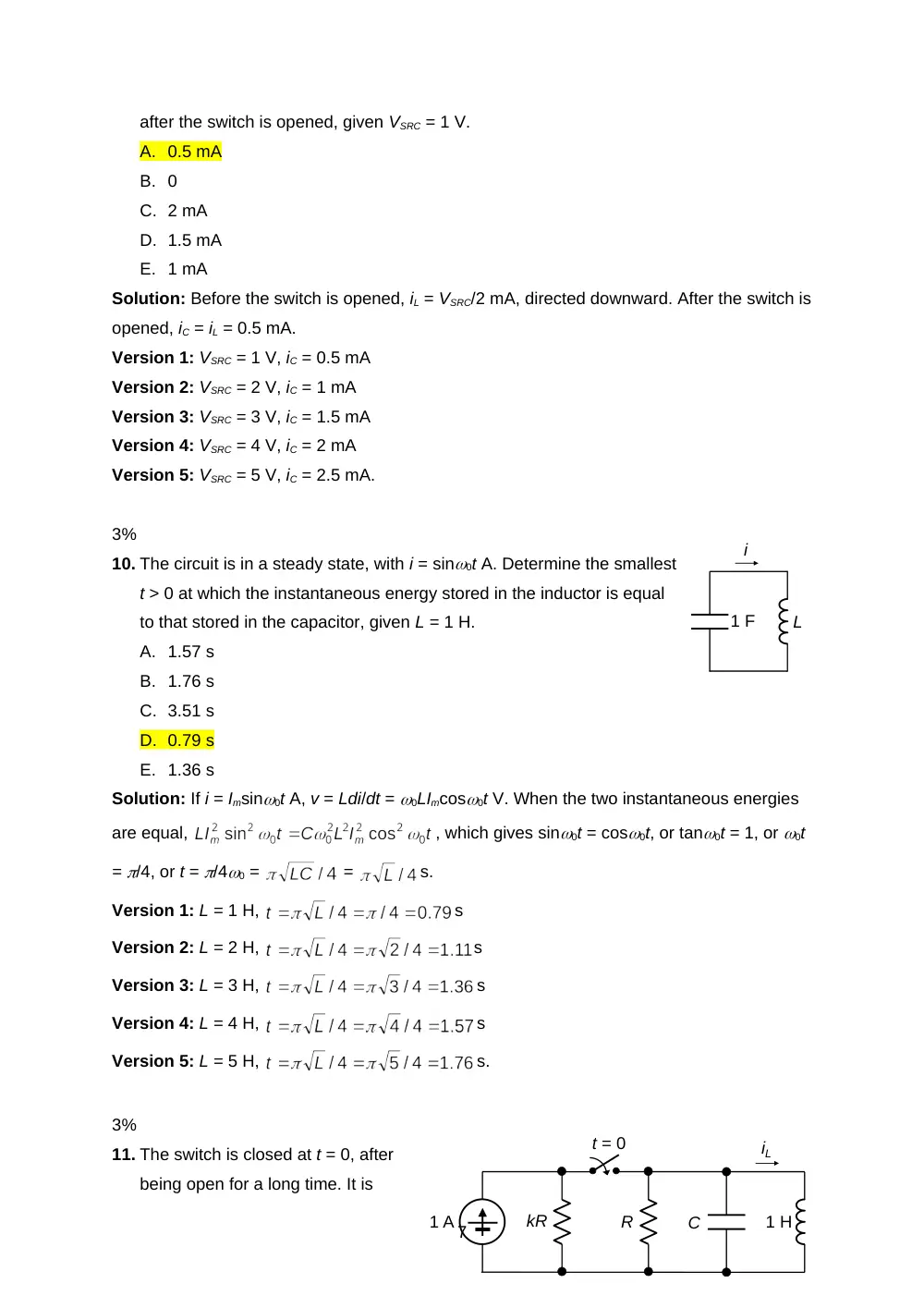
9.
The switch is opened at t = 0 after being
closed for a long time. Determine iC just
6
2 H
1 H
1 H
1 F
R
t = 0
2 H
1 F
R
3 H
-1 H
1:2
1 A
Z
a
b
+
–
iC
VSRC
1 k
1 k
0.5 F
5 mH
t = 0
1:2
Z
–
+
VT
0.5VT
+
–
IT
Z
VT
75
0.
Z
VT
1.5
after the switch is opened, given VSRC = 1 V.
A. 0.5 mA
B. 0
C. 2 mA
D. 1.5 mA
E. 1 mA
Solution: Before the switch is opened, iL = VSRC/2 mA, directed downward. After the switch is
opened, iC = iL = 0.5 mA.
Version 1: VSRC = 1 V, iC = 0.5 mA
Version 2: VSRC = 2 V, iC = 1 mA
Version 3: VSRC = 3 V, iC = 1.5 mA
Version 4: VSRC = 4 V, iC = 2 mA
Version 5: VSRC = 5 V, iC = 2.5 mA.
3%
10. The circuit is in a steady state, with i = sin0t A. Determine the smallest
t > 0 at which the instantaneous energy stored in the inductor is equal
to that stored in the capacitor, given L = 1 H.
A. 1.57 s
B. 1.76 s
C. 3.51 s
D. 0.79 s
E. 1.36 s
Solution: If i = Imsin0t A, v = Ldi/dt = 0LImcos0t V. When the two instantaneous energies
are equal,
, which gives sin0t = cos0t, or tan0t = 1, or 0t
= /4, or t = /40 =
=
s.
Version 1: L = 1 H,
s
Version 2: L = 2 H,
s
Version 3: L = 3 H,
s
Version 4: L = 4 H,
s
Version 5: L = 5 H,
s.
3%
11. The switch is closed at t = 0, after
being open for a long time. It is
7
L
i
1 F
R
C
1 A
t = 0
1 H
kR
iL
–
+
4(1 + j) A
Ix
5Ix
-j5
j40
j15
j10
10
-j40
a
b
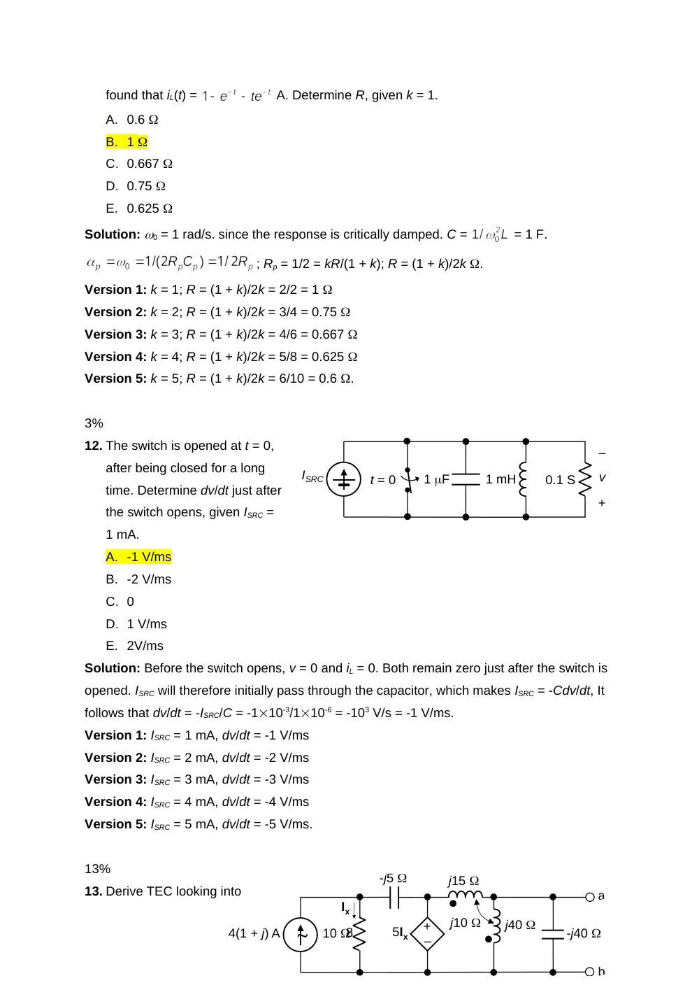
found that iL(t) =
A. Determine R, given k = 1.
A. 0.6
B. 1
C. 0.667
D. 0.75
E. 0.625
Solution: 0 = 1 rad/s. since the response is critically damped. C =
= 1 F.
; Rp = 1/2 = kR/(1 + k); R = (1 + k)/2k .
Version 1: k = 1; R = (1 + k)/2k = 2/2 = 1
Version 2: k = 2; R = (1 + k)/2k = 3/4 = 0.75
Version 3: k = 3; R = (1 + k)/2k = 4/6 = 0.667
Version 4: k = 4; R = (1 + k)/2k = 5/8 = 0.625
Version 5: k = 5; R = (1 + k)/2k = 6/10 = 0.6 .
3%
12. The switch is opened at t = 0,
after being closed for a long
time. Determine dv/dt just after
the switch opens, given ISRC =
1 mA.
A. -1 V/ms
B. -2 V/ms
C. 0
D. 1 V/ms
E. 2V/ms
Solution: Before the switch opens, v = 0 and iL = 0. Both remain zero just after the switch is
opened. ISRC will therefore initially pass through the capacitor, which makes ISRC = -Cdv/dt, It
follows that dv/dt = -ISRC/C = -110-3/110-6 = -103 V/s = -1 V/ms.
Version 1: ISRC = 1 mA, dv/dt = -1 V/ms
Version 2: ISRC = 2 mA, dv/dt = -2 V/ms
Version 3: ISRC = 3 mA, dv/dt = -3 V/ms
Version 4: ISRC = 4 mA, dv/dt = -4 V/ms
Version 5: ISRC = 5 mA, dv/dt = -5 V/ms.
13%
13. Derive TEC looking into
8
0.1 S
+
–
v
1 mH
ISRC
t = 0
1 F
–
+
ISRC
Ix
5Ix
j30
10
-j40
a
b
j5
-j5
j10
5Ix
I = 0
ISRC – Ix
terminal ‘ab’ (7 grades for VTh, 6 grades for ZTh).
Solution: Replacing the linear transformer by its T-equivalent circuit, it is seen that on open
circuit, the -j40 in series with
j10 gives -j30 . In parallel
with j30 , this results in an open
circuit. The current through the
-j5 is zero, so that both
terminals of this inductor are at
a
voltage 5IX. The current in the -j5
impedance is ISRC – Ix. From KVL, 10Ix + j5(ISRC – Ix) = 5Ix. This gives
A, and 5IX = 20 V. It
follows that VTh = Vab =
= 26.67 V.
On short circuit, the voltage of the dependent source
is still 20 V. The parallel impedance of j10 and j30 is
j7.5 . The current through the j5 impedance is 20/(j12.5)
A, From current division, ISC is this current multiplied by 3/4. This gives ISC = -j1.2 A. It follows
that ZTh = (80/3)/(-j1.2) = j200/9 = j22.22 .
13%
14. Determine Zin looking into terminals ‘ab’.
Solution: Let a test voltage of 5VT be applied. The
voltages across the two windings are 4VT and VT.
w The current in the RC branch is
. The current in the
inductive branch is:
= 0.25VT(1 – j).
Ix = 0.4VT(1 + j) – 0.25VT(1 – j) = VT(0.15 + j0.65).
From the mmf equation, 4I1 + I1 + VT(0.15 + j0.65)
= 0, which gives I1 = -VT(0.03 + j0.13); I = 0.4VT(1 +
j) – VT(0.03 + j0.13) = VT(0.37 + j0.27); Zin =
5VT/VT(0.37 + j0.27) = 10.92-36.12 = 8.818 –
j6.435 .
9
j30
a
b
j5
j10
20 V
ISC
–
+
j2
1600
turns
400
turns
a
b
10
-j10
2
–
+
–
+
–
+
Ix
I1
Ix + I1
I
VT
4VT
5VT
j2
1600
turns
400
turns
a
b
Zin
10
-j10
2
13%
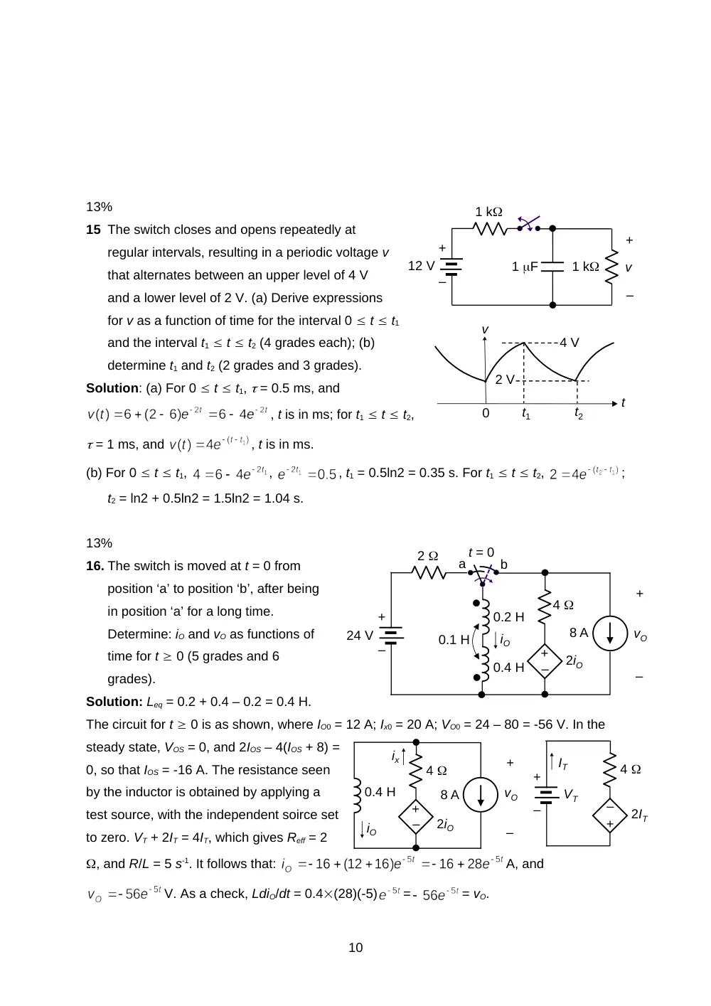
15 The switch closes and opens repeatedly at
regular intervals, resulting in a periodic voltage v
that alternates between an upper level of 4 V
and a lower level of 2 V. (a) Derive expressions
for v as a function of time for the interval 0 t t1
and the interval t1 t t2 (4 grades each); (b)
determine t1 and t2 (2 grades and 3 grades).
Solution: (a) For 0 t t1, = 0.5 ms, and
, t is in ms; for t1 t t2,
= 1 ms, and
, t is in ms.
(b) For 0 t t1,
,
, t1 = 0.5ln2 = 0.35 s. For t1 t t2,
;
t2 = ln2 + 0.5ln2 = 1.5ln2 = 1.04 s.
13%
16. The switch is moved at t = 0 from
position ‘a’ to position ‘b’, after being
in position ‘a’ for a long time.
Determine: iO and vO as functions of
time for t 0 (5 grades and 6
grades).
Solution: Leq = 0.2 + 0.4 – 0.2 = 0.4 H.
The circuit for t 0 is as shown, where IO0 = 12 A; Ix0 = 20 A; VO0 = 24 – 80 = -56 V. In the
steady state, VOS = 0, and 2IOS – 4(IOS + 8) =
0, so that IOS = -16 A. The resistance seen
by the inductor is obtained by applying a
test source, with the independent soirce set
to zero. VT + 2IT = 4IT, which gives Reff = 2
, and R/L = 5 s-1. It follows that:
A, and
V. As a check, LdiO/dt = 0.4(28)(-5)
=
= vO.
10
+
–
1 k
1 k
1 F
12 V
–
+
v
2 V
t
t1
t2
4 V
0
v
0.2 H
+
–
4
2
+
–
vO
iO
24 V
t = 0
8 A
a
b
–
+
0.4 H
0.1 H
2iO
4
+
–
vO
iO
8 A
–
+
0.4 H
2iO
ix
4
IT
–
+
2IT
+
–
VT