
EECE 210 Final with Solution, Fall 2011
American University of Beirut · Electric Circuits · 10 pages · with solution


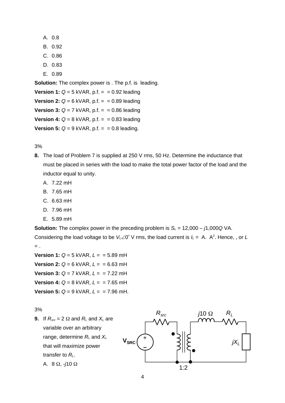


More EECE 210 files
- Final · Fall 2018Final examView
- Final · Spring 2016Final examView
- Final Exam-solution · Fall 2016Final exam · with solutionView
- Final With Solution · Fall 2014Final exam · with solutionView
- Final · Fall 2013Final examView
- Problems For Final -with Some Solutions · Fall 2012Final exam · with solutionView
- Final · Fall 2010Final examView
- Final · Fall 2009Final examView
Show the text of this final exam
EECE 210 – Final Exam
January 20, 2012
3%
1.
Determine Vy, assuming VSRC = 1 V.
A. 2 V
B. 4 V
C. 5 V
D. 1 V
E. 3 V
Solution: Vx = -2Vx1, which makes Vx = 0. It follows that Vy = VSRC.
Version 1: VSRC = 1 V, Vy = VSRC = 1 V
Version 2: VSRC = 2 V, Vy = VSRC = 2 V
Version 3: VSRC = 3 V, Vy = VSRC = 3 V
Version 4: VSRC = 4 V, Vy = VSRC = 4 V
Version 5: VSRC = 5 V, Vy = VSRC = 5 V.
3%
2.
Determine Vac, assuming all
resistances are 10 and VSRC = 2 V.
A. 3 V
B. 1 V
C. 5 V
D. 4 V
E. 2 V
Solution: From symmetry, nodes aa are
at the same voltage, as are nodes bb
and cc. These nodes can therefore be
joined together, which connects four
resistors in parallel in the two sets of
resistors in the middle, and results in the
circuit shown. Adding the two 2.5
resistors and splitting the resulting 5
resistor into two 10 resistors in parallel gives Vac
= VSRC/2.
Version 1: VSRC = 2 V, Vac = VSRC/2 = 1 V
Version 2: VSRC = 4 V, Vac = VSRC/2 = 2 V
1
–
+
–
+
VY
2Vx mA
–
+
Vx
VSRC
1 k
–
+
–
+
VSRC
VSRC
a
c
–
+
–
+
VSRC
VSRC
a
c
b
a
b
c
Version 3: VSRC = 6 V, Vac = VSRC/2 = 3 V
Version 4: VSRC = 8 V, Vac = VSRC/2 = 4 V
Version 5: VSRC = 10 V, Vac = VSRC/2 = 5 V.
3%
3.
Given a load impedance 0.1(4 + j3) . Determine the susceptance of the load.
A. 0.6 S
B. -0.6 S
C. -1.2 S
D. -0.3 S
E. 1.2 S
Solution: The load admittance is . Hence, S.
Version 1: k = 0.1, S
Version 2: k = 0.2, S
Version 3: k = 0.3, S
Version 4: k = 0.4, S
Version 5: k = 0.5, S.
3%
4.
If vSRC = 3cost V, determine at which
the voltage across the 10 resistor is a
maximum and specify this voltage.
A. 2 V, 2 krad/s
B. 4 V, 2 krad/s
C. 8 + j6 V, 1 krad/s
D. 8 – j6 V, 2 krad/s
E. 4 V, 4 krad/s
Solution: vSRC = Acost V. The voltage across the 10 resistor is maximum when the
parallel impedance of L and C is infinite, that is, when XL = -XC, which makes . This
occurs when , or rad/s. The voltage is VR = 2A/3 V.
Version 1: A = 3, VR = 2A/3 = 2 V
Version 2: A = 6, VR = 2A/3 = 4 V
Version 3: A = 9, VR = 2A/3 = 6 V
Version 4: A = 12, VR = 2A/3 = 8 V
Version 5: A = 15, VR = 2A/3 = 10 V.
3%
2
–
+
vSRC
0.5 mF
0.5 mH
10
5
5.
Determine the total reactive power absorbed by L and C in Problem 4 at = 4 krad/s
and with the 5 resistor replaced by a short circuit.
A. -13 VAR
B. +6.75 VAR
C. -27 VAR
D. 13 VAR
E. -6.75 VAR
Solution: The total reactive power absorbed is VAR.
Version 1: A = 3, -6.75 VAR
Version 2: A = 6, -27 VAR
Version 3: A = 9, -60.75 VAR
Version 4: A = 12, -108 VAR
Version 5: A = 15, -168.75 VAR.
3%
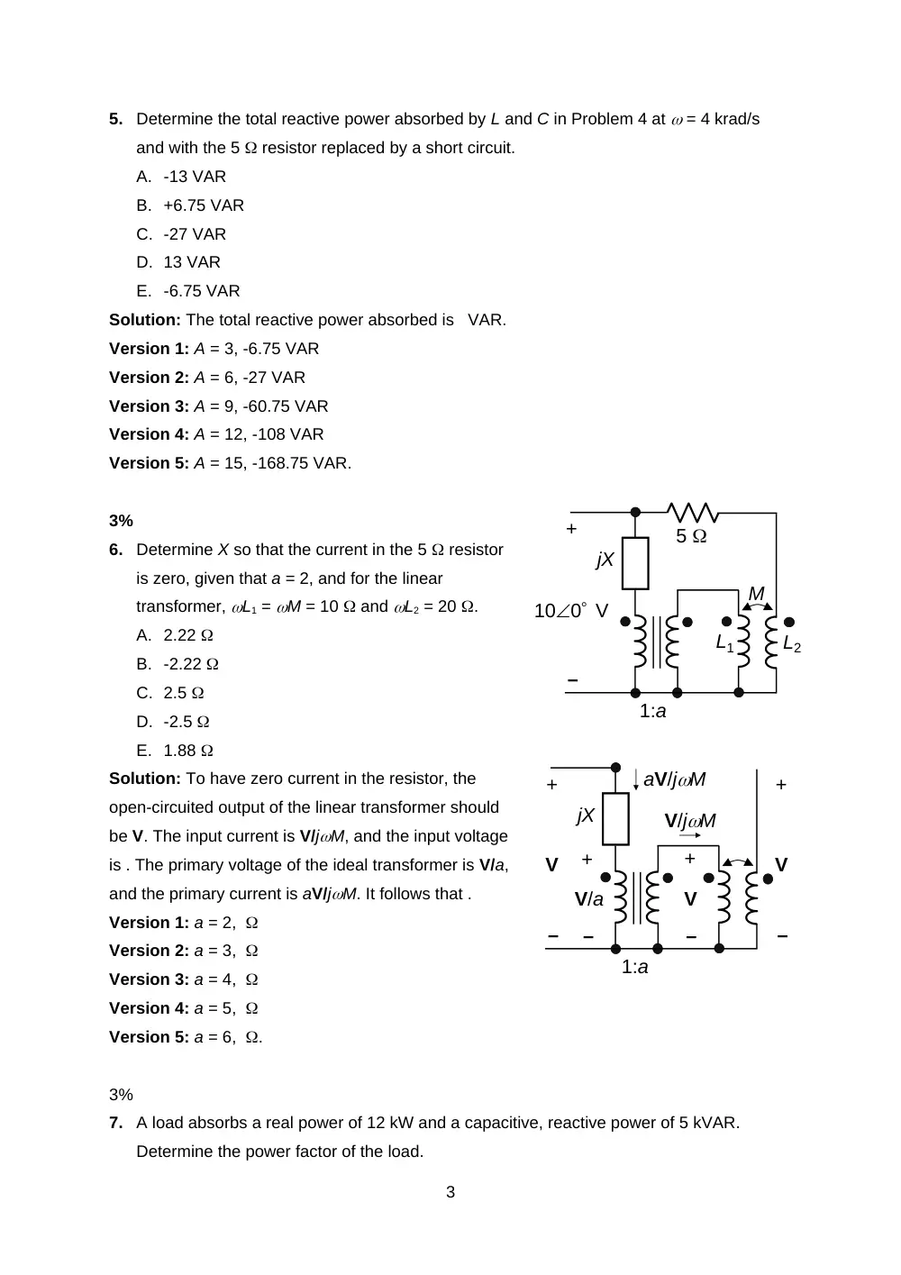
6.
Determine X so that the current in the 5 resistor
is zero, given that a = 2, and for the linear
transformer, L1 = M = 10 and L2 = 20 .
A. 2.22
B. -2.22
C. 2.5
D. -2.5
E. 1.88
Solution: To have zero current in the resistor, the
open-circuited output of the linear transformer should
be V. The input current is V/jM, and the input voltage
is . The primary voltage of the ideal transformer is V/a,
and the primary current is aV/jM. It follows that .
Version 1: a = 2,
Version 2: a = 3,
Version 3: a = 4,
Version 4: a = 5,
Version 5: a = 6, .
3%
7.
A load absorbs a real power of 12 kW and a capacitive, reactive power of 5 kVAR.
Determine the power factor of the load.
3
1:a
L1
L2
M
5
jX
–
+
100 V
jX
–
+
V
–
+
V
V/jM
aV/jM
–
+
V
–
+
V/a
1:a
A. 0.8
B. 0.92
C. 0.86
D. 0.83
E. 0.89
Solution: The complex power is . The p.f. is leading.
Version 1: Q = 5 kVAR, p.f. = = 0.92 leading
Version 2: Q = 6 kVAR, p.f. = = 0.89 leading
Version 3: Q = 7 kVAR, p.f. = = 0.86 leading
Version 4: Q = 8 kVAR, p.f. = = 0.83 leading
Version 5: Q = 9 kVAR, p.f. = = 0.8 leading.
3%
8.
The load of Problem 7 is supplied at 250 V rms, 50 Hz. Determine the inductance that
must be placed in series with the load to make the total power factor of the load and the
inductor equal to unity.
A. 7.22 mH
B. 7.65 mH
C. 6.63 mH
D. 7.96 mH
E. 5.89 mH
Solution: The complex power in the preceding problem is SL = 12,000 – j1,000Q VA.
Considering the load voltage to be VL0 V rms, the load current is IL = A. A2. Hence, , or L
= .
Version 1: Q = 5 kVAR, L = = 5.89 mH
Version 2: Q = 6 kVAR, L = = 6.63 mH
Version 3: Q = 7 kVAR, L = = 7.22 mH
Version 4: Q = 8 kVAR, L = = 7.65 mH
Version 5: Q = 9 kVAR, L = = 7.96 mH.
3%
9.
If Rsrc = 2 and RL and XL are
variable over an arbitrary
range, determine RL and XL
that will maximize power
transfer to RL.
A. 8 , -j10
4
–
+
RL
j10
1:2
VSRC
Rsrc
jXL
B. 10 , j10
C. 12 , -j10
D. 8 , j10
E. 10 , -j10
Solution: XLm = -j10 so as to cancel the +j10 , and RLm = 4Rsrc so as to match the source
and load resistances.
Version 1: Rsrc = 2 , RLm = 4Rsrc = 8
Version 2: Rsrc = 2.5 , RLm = 4Rsrc = 10
Version 3: Rsrc = 3 , RLm = 4Rsrc = 12
Version 4: Rsrc = 3.5 , RLm = 4Rsrc = 14
Version 5: Rsrc = 4 , RLm = 4Rsrc = 16 .
3%
10. In the circuit of Problem 9, Rsrc = 20 , RL = 3 , and XL = -j6 . Determine the ratio of
primary to secondary turns that will maximize power transfer to RL.
A. 4
B. 5
C. 3
D. 2
E. 6
Solution: Let the primary to secondary turns ratio be a. The secondary load impedance is ZL
= 3 + j10 – j6 = 3 + j4 . When reflected to the primary side, this becomes (3 + j4)a2, of
magnitude 5a2. For maximum power transfer, 5a2 = Rsrc, or .
Version 1: Rsrc = 20 ,
Version 2: Rsrc = 45 ,
Version 3: Rsrc = 80 ,
Version 4: Rsrc = 125 ,
Version 5: Rsrc = 180 , .
3%
11. If the primary to secondary turns ratio in problem 10 is 4 and vSRC = 16sin(100t) V,
determine the power dissipated in the 3 resistor.
A. 0.70 W
B. 0.18 W
C. 0.11 W
D. 0.48 W
E. 0.30 W
5
Solution: The magnitude of the source voltage referred to the secondary is 16/4 = 4 V, and
the source resistance is Rsrc /16 . The magnitude of the load current is A rms, and the
power dissipated is W.
Version 1: Rsrc = 20 , = 0.70 W
Version 2: Rsrc = 45 , = 0.48 W
Version 3: Rsrc = 80 , = 0.3 W
Version 4: Rsrc = 125 , = 0.18 W
Version 5: Rsrc = 180 , = 0.11 W.
3%
12. The exponential form of the Fourier series expansion of a periodic function is . Determine
the second harmonic in trigonometric form.
A. 0.5cos(n0t + 60)
B. 2cos(n0t + 60)
C. cos(n0t + 60)
D. 2.5cos(n0t + 60)
E. 1.5cos(n0t + 60)
Solution: The ac component is . , hence and . The trigonometric form of the nth harmonic is
= = . The second harmonic is .
Version 1: A = 1,
Version 2: A = 2,
Version 3: A = 3,
Version 4: A = 4,
Version 5: A = 5, .
3%
13. The function shown has a0 = 0 and for n = 1, 2, 3,
etc.:
A. an = 0, bn = 0 for even n only and can be
determined by integrating the function from
t = 0 to t = T/2
B. an = 0, bn = 0 for even n only and can be
determined by integrating the function from
t = 0 to t = T/4
C. an = 0, bn = 0 for odd n only and can be determined by integrating the function from
t = 0 to t = T/2
D. an = 0, bn = 0 for odd n only and can be determined by integrating the function from
6
A
2A
-A
-2A
T/4
T/2
3T/4
T
t
t = 0 to t = T/4
E. an 0, bn 0, for all n, and both can be determined by integrating the function from t
= 0 to t = T/2
Solution: The waveform is half-wave symmetric, is not quarter-wave symmetric, and is
neither odd nor even. Hence, an = 0, bn = 0 for even n, and can be determined by integrating
the function from t = 0 to t = T/2.
3%
14. If Frms is the rms value of a half-wave symmetric, periodic waveform, determine the rms
value of the same function but with the negative half-waves missing.
A.
B.
C.
D.
E.
Solution: + = . Hence,
3%
15. Specify how the magnitude of the nth harmonic varies
with n for the periodic function shown.
A. n
B. n2
C. 1/n
D. 1/n2
E. 1/n3
Solution: Since the function is discontinuous, the magnitude of the nth harmonic varies as
1/n.
11%
16. Determine Thevenin’s equivalent circuit
between terminals ab, assuming VSRC =
50 V. Express VTh in polar coordinates
and ZTh in rectangular coordinates.
Solution: The current in the LC branch is VX/j5
= -j0.2Vx, and the current in the middle
branch is 0.2(1 – j)Vx. From KVL, VSRC –
50.2(1 – j)Vx = VX + (-j2.5)(-j0.2)Vx =
7
–
+
VSRC
5
0.2VX
j5
-j2.5
b
a
–
+
VX
–
+
VSRC
5
j5
-j2.5
b
–
+
VX
b
a
0.2VX
-j0.2VX
0.2(1 – j)VX
0.5Vx, or Vx = VSRC/(1.5 – j), VTh = 0.5VX = V. When terminals ab are short circuited, the
current source is zero, and ISC = A. It follows that ZTh = (1.15 + j0.77) .
Version 1: VSRC = 50 V, V
Version 2: VSRC = 100 V, V
Version 3: VSRC = 150 V, V
Version 4: VSRC = 200 V, V
Version 5: VSRC = 250 V, V.
11%
17. Determine vO(t), assuming vSRC =
2cos1000t V.
Solution: The impedances of the reactive
elements are: mH j8 , 1 mH j , 2 mH
j2 , and 0.5 mF -j2 . The circuit in the
frequency domain becomes as shown, with the
linear transformer replaced by its T-
equivalent circuit. The parallel
impedance to the right of terminals ab is
, and Vab = = = -j0.6VSRC. It follows that
= -0.3(1 + j)VSRC = V, and vO(t) = V.
Version 1: Vm = 2, vO(t) = = -
0.85cos(1000t + 45) V
Version 2: Vm = 3, vO(t) = = -
1.27cos(1000t + 45) V
Version 3: Vm = 4, vO(t) = = -1.70cos(1000t + 45) V
Version 4: Vm = 5, vO(t) = = -2.12cos(1000t + 45) V
Version 5: Vm = 6, vO(t) = = -2.55cos(1000t + 45) V.
11%
18. RL is variable in the range (1, 8 ).
Determine RL for maximum power
transfer and the maximum power
transferred to it, assuming B = 4.
Solution: Thevenin’s voltage for the
Bsin20t source, as seen by RL, is
Bsin20t V. From superposition, Thevenin’s voltage for the cos0t sources is (2 +
100.2)cos0t = 4cos0t V. RTh = 10 . Hence, for maximum power transfer RL = 8 . The
power dissipated in RL is PL = W.
8
–
+
2cos0t V
10
–
+
5
RL
Bsin20t V
0.2cos0t A
1 mH
1 mH
2 mH
6 mH
2
–
+
3
0.5 mF
–
+
vO
vSRC
2
–
+
3
–
+
VO
VSRC
-j2
-j
j2
j3
j6
b
a
Version 1: B = 4, PL = (B2 + 16)/81 = 32/81 = 0.396 W
Version 2: B = 6, PL = (B2 + 16)/81 = 52/81 = 0.642 W
Version 3: B = 8 PL = (B2 + 16)/81 = 80/81 = 0.988 W
Version 4: B = 10, PL = (B2 + 16)/81 = 116/81 = 1.432 W
Version 5: B = 12, PL = (B2 + 16)/81 = 160/81 = 1.975 W.
11%
19. Derive the first four terms of the trigonometric Fourier
series expansion of the periodic function f(t) = Asint,
-/2 t /2, with A = 1. Note that:
Solution: The function is odd and of zero average. Hence a0 = 0, an =0 for all integer n,
and , where T = and 0 = 2/T = 2. Using the trigonometric relation for the product of two
sine functions, ==. Hence,
Version 1: A = 1,
Version 2: A = 2,
Version 3: A = 3,
Version 4: A = 4,
Version 5: A = 5, .
11%
20. Determine the rms value of the periodic function shown,
assuming A = 1.
Solution: The function has an average value of 0.25 A,
because the areas under the positive and negative triangles
cancel out, and the areas under the rectangles are 0.5 A –
0.25A. Alternatively, it can be argued that if 0.25A is
subtracted from f(t), the function becomes symmetrical with
respect to the horizontal axis The ac component of f(t) = A(2t + 0.75), 0 t 0.25 s. The
area under the square of the function over this time interval is = == The mean square is
obtained by dividing by 0.25, which gives . The square of the rms value of f(t) is = and the
rms value is .
Version 1: A = 1, rms value is = 1.041
9
A
1.5A
-0.5A
-A
0.25
0.75
0.5
1
t, s
f(t)
A
-A
/2
-/2
t
f(t)
Version 2: A = 2, rms value is = 2.082
Version 3: A = 3, rms value is = 3.122
Version 4: A = 4, rms value is = 4.163
Version 5: A = 5, rms value is = 5.204.
10