
EECE 210 Final, Fall 2018
American University of Beirut · Electric Circuits · 5 pages


More EECE 210 files
- Final Exam-solution · Fall 2016Final exam · with solutionView
- Final · Spring 2016Final examView
- Final With Solution · Fall 2014Final exam · with solutionView
- Final · Fall 2013Final examView
- Problems For Final -with Some Solutions · Fall 2012Final exam · with solutionView
- Final with Solution · Fall 2011Final exam · with solutionView
- Final · Fall 2010Final examView
- Final · Fall 2009Final examView
Show the text of this final exam
EECE 210 Electric Circuits
Final Exam – Dec 19, 2018
20%
1.
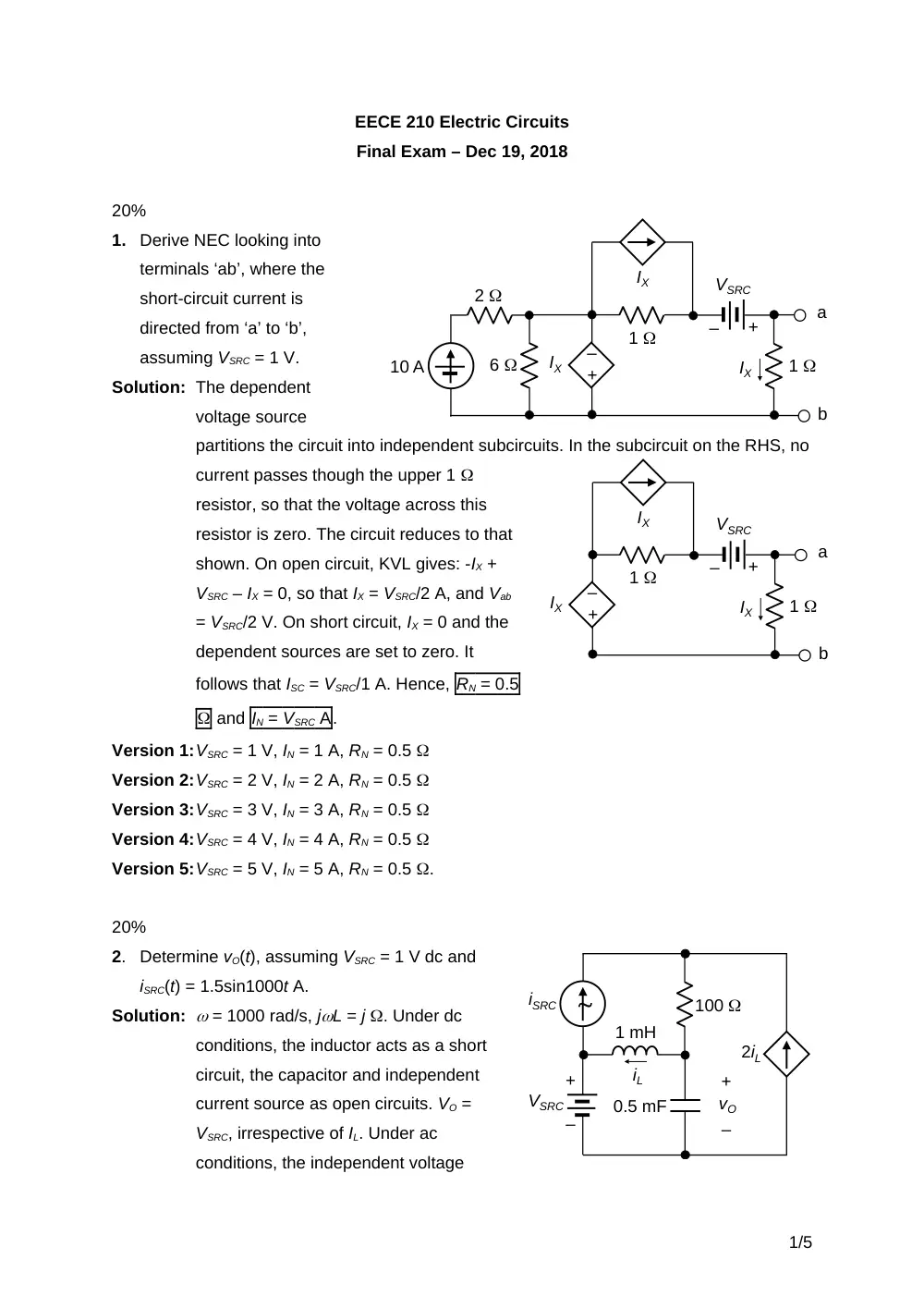
Derive NEC looking into
terminals ‘ab’, where the
short-circuit current is
directed from ‘a’ to ‘b’,
assuming VSRC = 1 V.
Solution: The dependent
voltage source
partitions the circuit into independent subcircuits. In the subcircuit on the RHS, no
current passes though the upper 1
resistor, so that the voltage across this
resistor is zero. The circuit reduces to that
shown. On open circuit, KVL gives: -IX +
VSRC – IX = 0, so that IX = VSRC/2 A, and Vab
= VSRC/2 V. On short circuit, IX = 0 and the
dependent sources are set to zero. It
follows that ISC = VSRC/1 A. Hence, RN = 0.5
and IN = VSRC A.
Version 1:VSRC = 1 V, IN = 1 A, RN = 0.5
Version 2:VSRC = 2 V, IN = 2 A, RN = 0.5
Version 3:VSRC = 3 V, IN = 3 A, RN = 0.5
Version 4:VSRC = 4 V, IN = 4 A, RN = 0.5
Version 5:VSRC = 5 V, IN = 5 A, RN = 0.5 .
20%
2.
Determine vO(t), assuming VSRC = 1 V dc and
iSRC(t) = 1.5sin1000t A.
Solution: = 1000 rad/s, jL = j . Under dc
conditions, the inductor acts as a short
circuit, the capacitor and independent
current source as open circuits. VO =
VSRC, irrespective of IL. Under ac
conditions, the independent voltage
1/5
+
–
+
–
vO
2iL
100
1 mH
0.5 mF
iSRC
VSRC
iL
–
+
10 A
2
6
IX
+
–
1
VSRC
1
IX
a
b
IX
–
+
IX
+
–
1
VSRC
1
IX
a
b
IX
source acts as a short circuit. The downward current in the 100 resistor is (ISRC
+ 2IL) A in the frequency domain. This current divides between the inductor and
capacitor. IL =
, or,
, or,
. VO = jLIL =
. Substituting numerical values, VO =
V. The ac component of vO(t) =
=
.
It follows that: vO(t) =
V.
Version 1:VSRC = 1 V, Isrc = 1.5 A; vO(t) =
V
Version 2: VSRC = 2 V, Isrc = 3 A; vO(t) =
V
Version 3:VSRC = 3 V, Isrc = 4.5 A; vO(t) =
V
Version 4:VSRC = 4 V, Isrc = 6 A; vO(t) =
V
Version 5:VSRC = 5 V, Isrc = 7.5 A; vO(t) =
V.
20%
3.
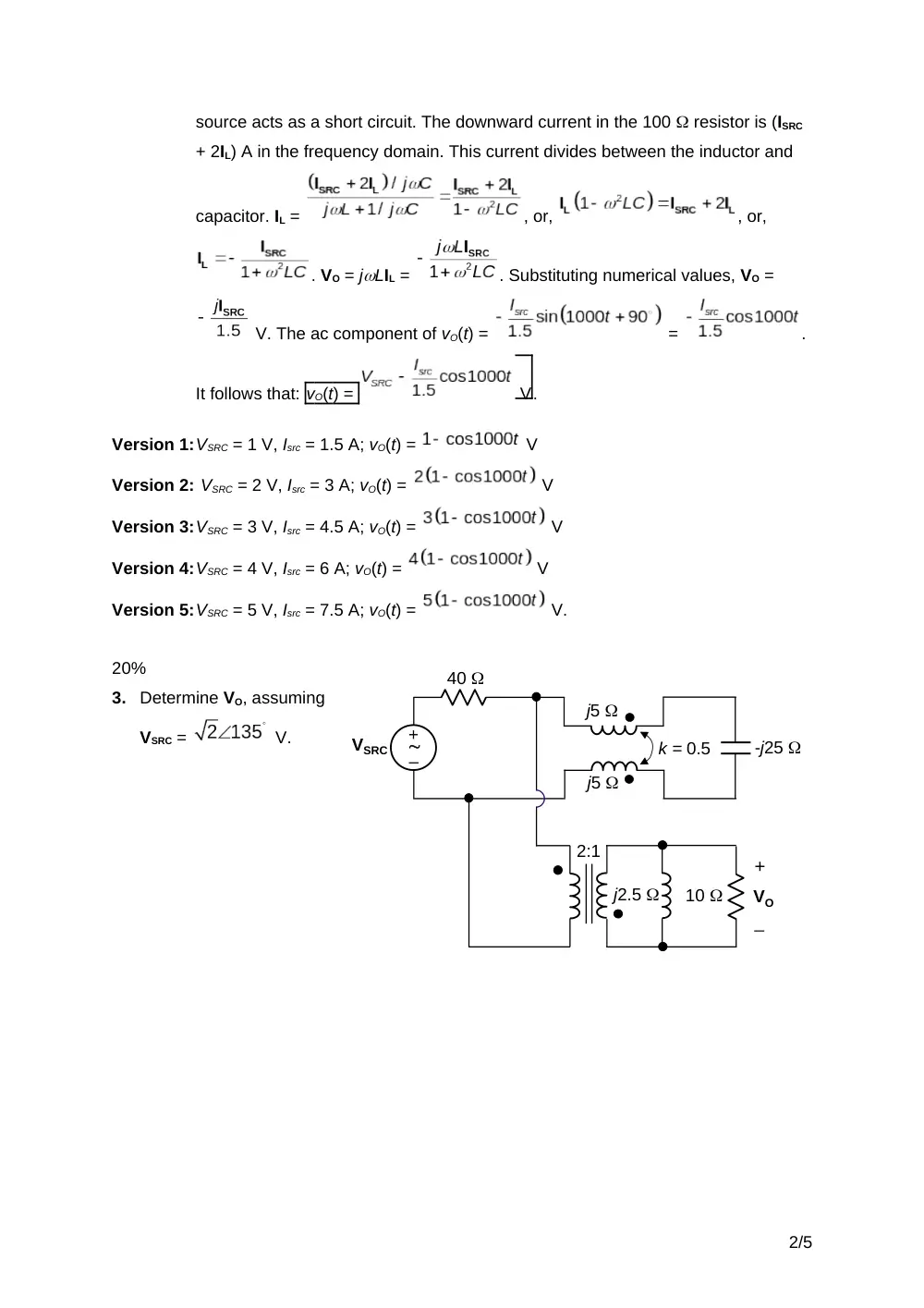
Determine VO, assuming
VSRC =
V.
2/5
–
+
2:1
VO
_
+
j2.5
10
-j25
40
j5
j5
k = 0.5
VSRC
Solution: The impedance seen at the primary of the ideal
transformer will be derived. The impedance on
the secondary side of the ideal transformer is
reflected to the primary side as a reactance of j10
in parallel with a resistance of 40 , with -2VO
appearing across the parallel combination, as shown. The two series-coupled
coils in series with the capacitor will have a reactance of: j10 – j5 – j25 = -j20 .
The two reactances in
parallel are
. TEC
seen by this reactance is
in series with 20 , the circuit becoming as shown. It follows that:
=
and
.
Version 1:VSRC =
= (-1 + j) V;
= 0.25 V
Version 2: VSRC = 2
= 2(-1 + j) V;
= 0.5 V
Version 3:VSRC = 3
= 3(-1 + j) V;
= 0.75 V
Version 4:VSRC = 4
= 4(-1 + j) V;
= 1 V
Version 5:VSRC = 5
= 5(-1 + j) V;
= 1.25 V
20%
4.
The switch is opened at t = 0 after being closed for a long
time. Determine RL and C so that the voltage vS across the
open switch is a constant for t 0+, assuming RC = 1
and L = 1 H.
Solution: In the steady state, with the switch closed, the
inductor acts as short circuit and the capacitor as an
open circuit. A current 5/RC flows, establishing a
voltage of 5 V across C. At t = 0+, the initial current
3/5
–
+
40
VSRC
40
-j20
j10
-2VO
_
+
+
–5 V
+
–
vS
C
L
RC
RL
t = 0
+
–5 V
+
–
vS
C
L
RC
RL
+
–
+
–
vC
vL
iL
through L is 5/RC and the initial voltage across C is 5 V. For t > 0+, L and C will each
discharge independently through the parallel resistance, as first-order circuits, so
that
and
. vS = 5 – vC – vL = 5
. For vS to be a constant, the two exponential terms must cancel out.
It follows that RL = RC and
, or
.
Version 1: RC = 1 , L = 1 H; RL = 1 , and C = 1 F
Version 2: RC = 2 , L = 2 H; RL = 2 , and C = 2/4 = 0.5 F
Version 3: RC = 3 , L = 3 H; RL = 3 , and C = 3/9 = 0.33 F
Version 4: RC = 4 , L = 4 H; RL = 4 , and C = 3/16 = 0.25 F
Version 5: RC = 5 , L = 5 H; RL = 5 , and C = 5/25 = 0.2 F.
20%
5.
Switch S1 is opened at t = 0 with
no initial energy stored in the
circuit. Switch S2 is moved from
position ‘a’ to position ‘b’ at t = t0,
at the first zero of iL for t > 0+.
Determine (a) t0, (b) iC(t) and vC(t)
for t ≥ 0+, where t is in ms. Assume that ISRC = 1 mA and VSRC = 5 V.
Solution: (a) 0
t
t 0: vC(t) = Acos0t + Bsin0t, since there can be no steady value of vC.
At t = 0+, vC(0+) = 0, so that A = 0, and vC(t) = Bsin0t V. iC(t) = 0CBcos0t. At
t = 0+, iC(0+) = ISRC, so that B = ISRC/0C, and iC(t) = ISRCcos0t. iL(t) = ISRC – iC(t)
= ISRC(1 – cos0t) A. The first zero of iL(t) for t > 0+ occurs at t0 = 2/0, where
rad/s, so that
ms.
(b) 0
t
t 0: vC(t) = (ISRC/0C)sin0t = (ISRC×10-3/(104×10-7)sin10t = ISRCsin10t V,
where ISRC is in mA and t is in ms. iC(t) = ISRCcos10t mA.
t
t 0: At t = t0, vC(t0) = 0 and iC(t) =ISRC mA. At this instant, switch S2 is moved
to position ‘b’, which makes iC(t0) =ISRC +
= (ISRC + 5) mA, and the final
value is zero, when the capacitor is fully charged. = 103×10-7 0.1 ms.
Hence,
mA, where t is in ms. The final value of vC(t)
4/5
t = 0
0.1 H
ISRC
+
–
VSRC
1 k
iC
+
–
vC
t = t0
S1
S2
a
b
iL
0.1 F
is: ISRC×1 + 5 = (ISRC + 5) V. Hence,
V.
Version 1:ISRC = 1 mA: iC(t) = cos10t mA, vC(t) = sin10t V, 0 t t0
mA,
V, t t0.
Version 2:ISRC = 2 mA: iC(t) = 2cos10t mA, vC(t) = 2sin10t V, 0 t t0
mA,
V, t t0.
Version 3:ISRC = 3 mA: iC(t) = 3cos10t mA, vC(t) = 3sin10t V, 0 t t0
mA,
V, t t0.
Version 4:ISRC = 4 mA: iC(t) = 4cos10t mA, vC(t) = 4sin10t V, 0 t t0
mA,
V, t t0.
Version 5:ISRC = 5 mA: iC(t) = 5cos10t mA, vC(t) = 5sin10t V, 0 t t0
mA,
V, t t0.
5/5