
EECE 210 Final With Solution, Fall 2014
American University of Beirut · Electric Circuits · 8 pages · with solution
More EECE 210 files
- Final · Fall 2018Final examView
- Final · Spring 2016Final examView
- Final Exam-solution · Fall 2016Final exam · with solutionView
- Final · Fall 2013Final examView
- Problems For Final -with Some Solutions · Fall 2012Final exam · with solutionView
- Final with Solution · Fall 2011Final exam · with solutionView
- Final · Fall 2010Final examView
- Final · Fall 2009Final examView
Show the text of this final exam
+
–
10
0.2 F
VSRC
+
–
vC
t = 0
EECE 210
Final Exam, December 13, 2014
3%
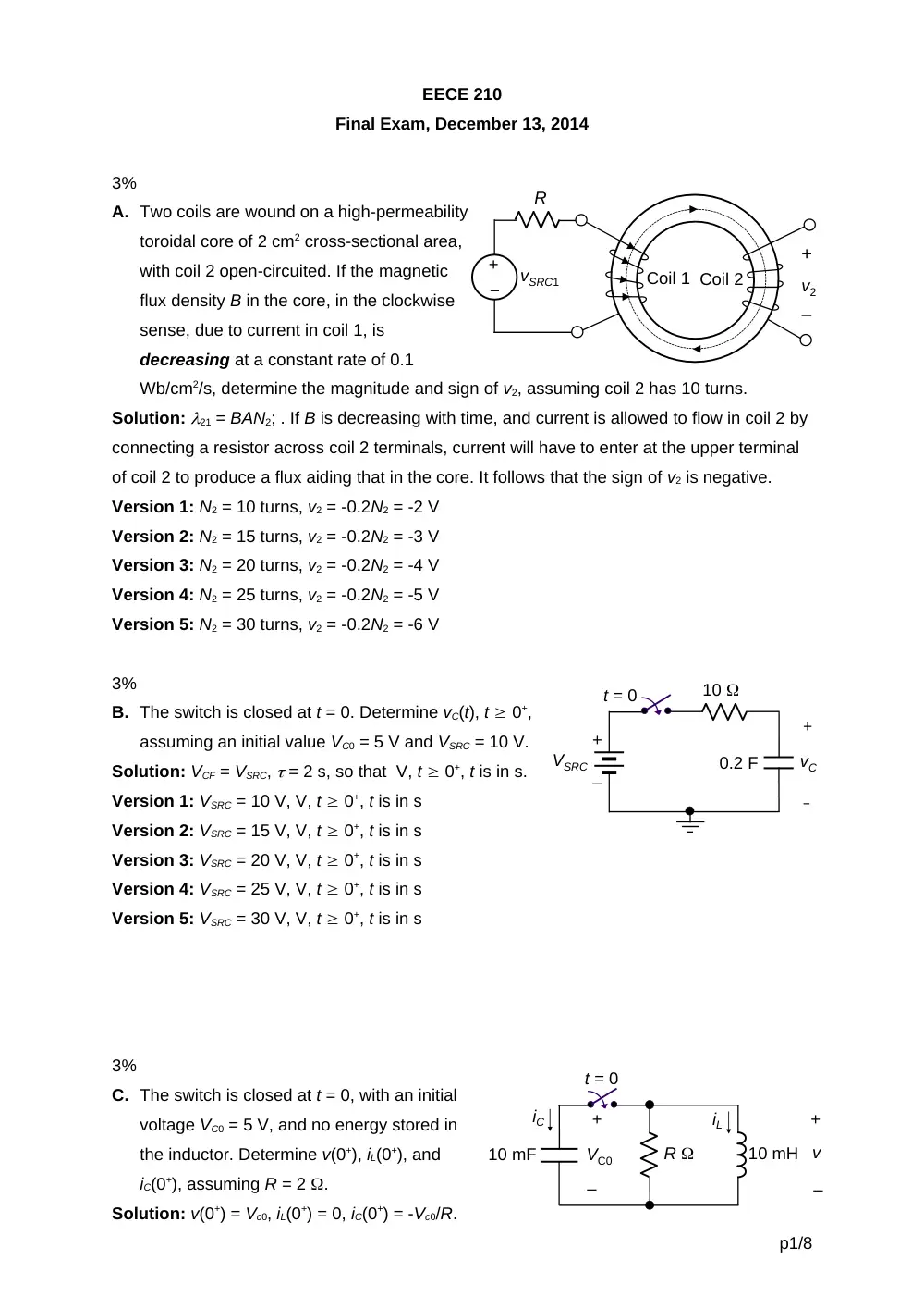
A. Two coils are wound on a high-permeability
toroidal core of 2 cm2 cross-sectional area,
with coil 2 open-circuited. If the magnetic
flux density B in the core, in the clockwise
sense, due to current in coil 1, is
decreasing at a constant rate of 0.1
Wb/cm2/s, determine the magnitude and sign of v2, assuming coil 2 has 10 turns.
Solution: 21 = BAN2; . If B is decreasing with time, and current is allowed to flow in coil 2 by
connecting a resistor across coil 2 terminals, current will have to enter at the upper terminal
of coil 2 to produce a flux aiding that in the core. It follows that the sign of v2 is negative.
Version 1: N2 = 10 turns, v2 = -0.2N2 = -2 V
Version 2: N2 = 15 turns, v2 = -0.2N2 = -3 V
Version 3: N2 = 20 turns, v2 = -0.2N2 = -4 V
Version 4: N2 = 25 turns, v2 = -0.2N2 = -5 V
Version 5: N2 = 30 turns, v2 = -0.2N2 = -6 V
3%
B. The switch is closed at t = 0. Determine vC(t), t 0+,
assuming an initial value VC0 = 5 V and VSRC = 10 V.
Solution: VCF = VSRC, = 2 s, so that V, t 0+, t is in s.
Version 1: VSRC = 10 V, V, t 0+, t is in s
Version 2: VSRC = 15 V, V, t 0+, t is in s
Version 3: VSRC = 20 V, V, t 0+, t is in s
Version 4: VSRC = 25 V, V, t 0+, t is in s
Version 5: VSRC = 30 V, V, t 0+, t is in s
3%
C. The switch is closed at t = 0, with an initial
voltage VC0 = 5 V, and no energy stored in
the inductor. Determine v(0+), iL(0+), and
iC(0+), assuming R = 2 .
Solution: v(0+) = Vc0, iL(0+) = 0, iC(0+) = -Vc0/R.
p1/8
–
+
vSRC1
Coil 1 Coil 2
R
v2
+
_
+
–
10 mH
10 mF
v
iL
iC
t = 0
+
–
VC0
R
Version 1: VC0 = 5 V; v(0+) = 5 V, iL(0+) = 0, iC(0+) = -Vc0/R = -5/2 = -2.5 A
Version 2: VC0 = 10 V; v(0+) = 10 V, iL(0+) = 0, iC(0+) = -Vc0/R = -10/2 = -5 A
Version 3: VC0 = 15 V; v(0+) = 15 V, iL(0+) = 0, iC(0+) = -Vc0/R = -15/2 = -7.5 A
Version 4: VC0 = 20 V; v(0+) = 20 V, iL(0+) = 0, iC(0+) = -Vc0/R = -20/2 = -10 A
Version 5: VC0 = 25 V; v(0+) = 25 V, iL(0+) = 0, iC(0+) = -Vc0/R = -25/2 = -12.5 A
3%
D. Specify whether the response for t 0+ in the preceding problem is overdamped,
critically damped, or underdamped, assuming R = 0.2 .
Solution: rad/s;
Version 1: R = 0.2 ; p = 50/0.2 = 250 rad/s, response is overdamped
Version 2: R = 0.4 ; p = 50/0.4 = 125 rad/s, response is overdamped
Version 3: R = 0.5 ; p = 50/0.5 = 100 rad/s, response is critically damped
Version 4: R = 0.8 ; p = 50/0.8 = 62.5 rad/s, response is underdamped
Version 5: R = 1 ; p = 50/1 = 50 rad/s, response is underdamped
3%
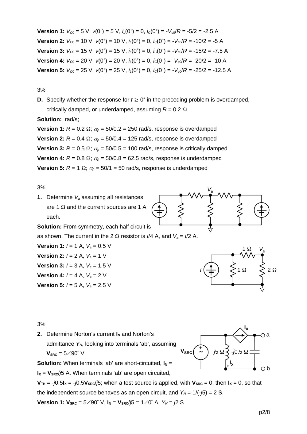
1.
Determine Va assuming all resistances
are 1 and the current sources are 1 A
each.
Solution: From symmetry, each half circuit is
as shown. The current in the 2 resistor is I/4 A, and Va = I/2 A.
Version 1: I = 1 A, Va = 0.5 V
Version 2: I = 2 A, Va = 1 V
Version 3: I = 3 A, Va = 1.5 V
Version 4: I = 4 A, Va = 2 V
Version 5: I = 5 A, Va = 2.5 V
3%
2.
Determine Norton’s current IN and Norton’s
admittance YN, looking into terminals ‘ab’, assuming
VSRC = 590 V.
Solution: When terminals ‘ab’ are short-circuited, IN =
IX = VSRC/j5 A. When terminals ‘ab’ are open circuited,
VTH = -j0.5IX = -j0.5VSRC/j5; when a test source is applied, with VSRC = 0, then IX = 0, so that
the independent source behaves as an open circuit, and YN = 1/(-j5) = 2 S.
Version 1: VSRC = 590 V, IN = VSRC/j5 = 10 A, YN = j2 S
p2/8
–
+
VSRC
j5
-j0.5
IX
IX
a
b
Va
Va
I
1
1
2
Version 2: VSRC = 1090 V, IN = VSRC/j5 = 20 A, YN = j2 S
Version 3: VSRC = 1590 V, IN = VSRC/j5 = 30 A, YN = j2 S
Version 4: VSRC = 2090 V, IN = VSRC/j5 = 40 A, YN = j2 S
Version 5: VSRC = 2590 V, IN = VSRC/j5 = 50 A, YN = j2 S
3%
3.
Determine the net average power delivered in
the circuit, assuming VSRC = 100 V.
Solution: The net average power delivered is
equal to the average power dissipated in the 4
resistor. When the current source is set to zero, the
current in the inductive branch is A. When the
voltage source is set to zero, the current in the inductive branch is A. By superposition, the
total current in the inductive branch is . The magnitude of this current is , and the average
power dissipated is W.
Version 1: VSRC = 100 V, = 2 W
Version 2: VSRC = 150 V, = 8 W
Version 3: VSRC = 200 V, = 18 W
Version 4: VSRC = 250 V, = 32 W
Version 5: VSRC = 300 V, = 50 W
3%
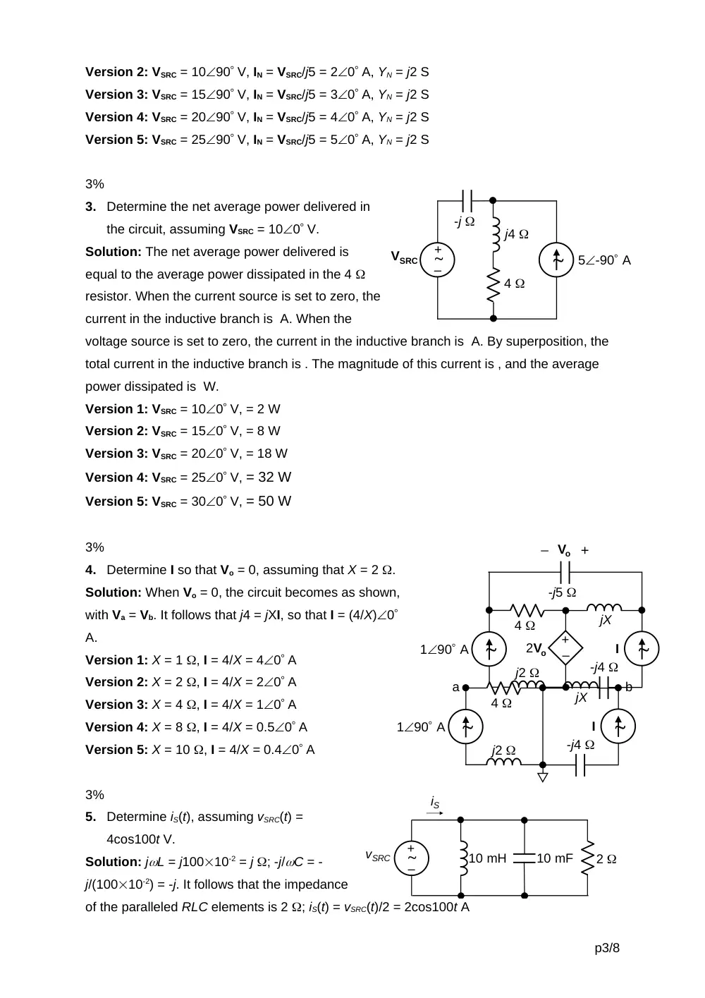
4.
Determine I so that Vo = 0, assuming that X = 2 .
Solution: When Vo = 0, the circuit becomes as shown,
with Va = Vb. It follows that j4 = jXI, so that I = (4/X)0
A.
Version 1: X = 1 , I = 4/X = 40 A
Version 2: X = 2 , I = 4/X = 20 A
Version 3: X = 4 , I = 4/X = 10 A
Version 4: X = 8 , I = 4/X = 0.50 A
Version 5: X = 10 , I = 4/X = 0.40 A
3%
5.
Determine iS(t), assuming vSRC(t) =
4cos100t V.
Solution: jL = j10010-2 = j ; -j/C = -
j/(10010-2) = -j. It follows that the impedance
of the paralleled RLC elements is 2 ; iS(t) = vSRC(t)/2 = 2cos100t A
p3/8
–
+
Vo +
_
-j5
jX
4
-j4
j2
2Vo
I
190 A
jX
4
-j4
j2
I
190 A
a
b
–
+
vSRC
10 mH
10 mF
2
iS
–
+
VSRC
5-90 A
-j
j4
4
Version 1: vSRC(t) = 4cos100t V; iS(t) = vSRC(t)/2 = 2cos100t A
Version 2: vSRC(t) = 6cos100t V; iS(t) = vSRC(t)/2 = 3cos100t A
Version 3: vSRC(t) = 8cos100t V; iS(t) = vSRC(t)/2 = 4cos100t A
Version 4: vSRC(t) = 10cos100t V; iS(t) = vSRC(t)/2 = 5cos100t A
Version 5: vSRC(t) = 12cos100t V; iS(t) = vSRC(t)/2 = 6cos100t A
3%
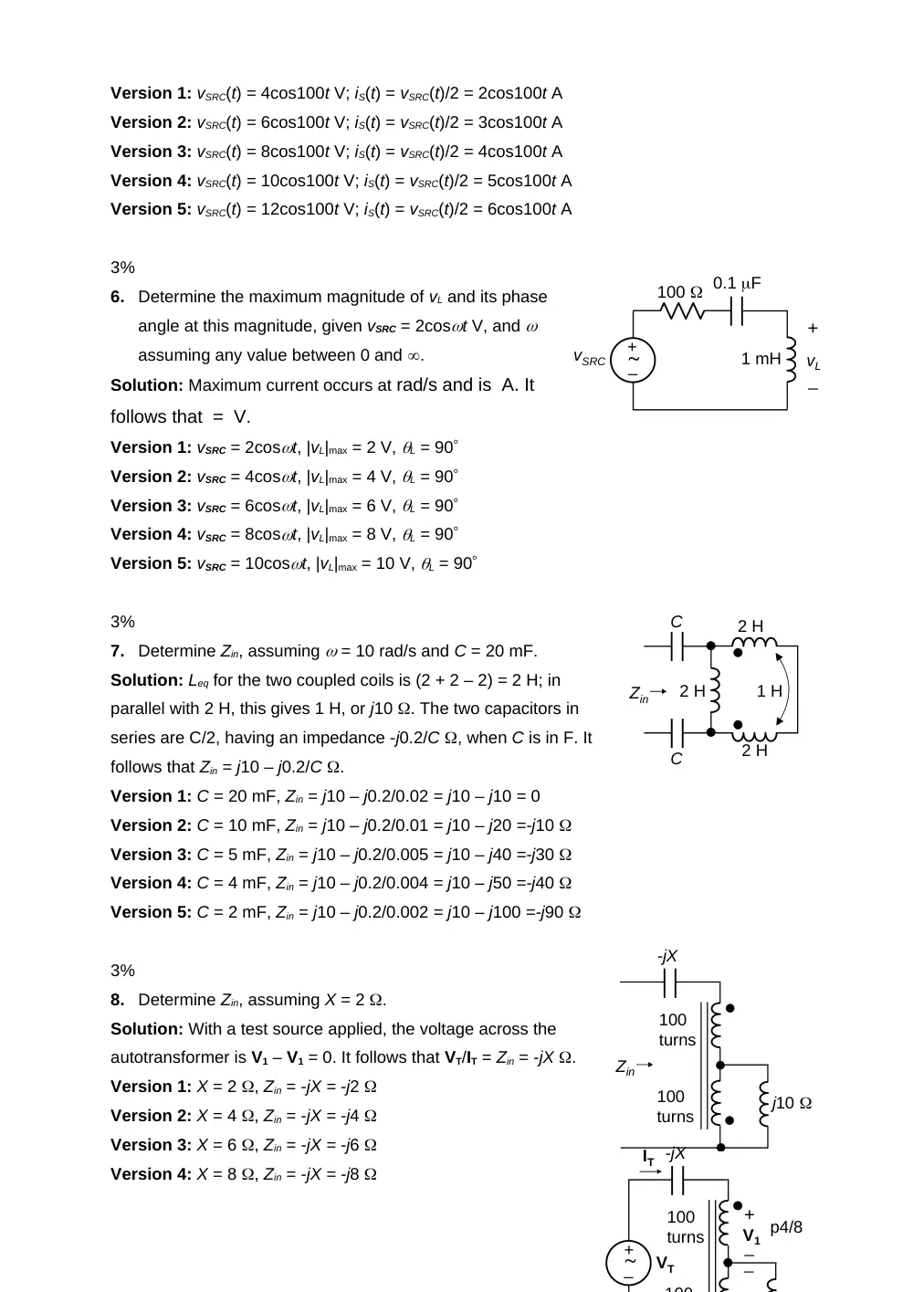
6.
Determine the maximum magnitude of vL and its phase
angle at this magnitude, given vSRC = 2cost V, and
assuming any value between 0 and .
Solution: Maximum current occurs at rad/s and is A. It
follows that = V.
Version 1: vSRC = 2cost, |vL|max = 2 V, L = 90
Version 2: vSRC = 4cost, |vL|max = 4 V, L = 90
Version 3: vSRC = 6cost, |vL|max = 6 V, L = 90
Version 4: vSRC = 8cost, |vL|max = 8 V, L = 90
Version 5: vSRC = 10cost, |vL|max = 10 V, L = 90
3%
7.
Determine Zin, assuming = 10 rad/s and C = 20 mF.
Solution: Leq for the two coupled coils is (2 + 2 – 2) = 2 H; in
parallel with 2 H, this gives 1 H, or j10 . The two capacitors in
series are C/2, having an impedance -j0.2/C , when C is in F. It
follows that Zin = j10 – j0.2/C .
Version 1: C = 20 mF, Zin = j10 – j0.2/0.02 = j10 – j10 = 0
Version 2: C = 10 mF, Zin = j10 – j0.2/0.01 = j10 – j20 =-j10
Version 3: C = 5 mF, Zin = j10 – j0.2/0.005 = j10 – j40 =-j30
Version 4: C = 4 mF, Zin = j10 – j0.2/0.004 = j10 – j50 =-j40
Version 5: C = 2 mF, Zin = j10 – j0.2/0.002 = j10 – j100 =-j90
3%
8.
Determine Zin, assuming X = 2 .
Solution: With a test source applied, the voltage across the
autotransformer is V1 – V1 = 0. It follows that VT/IT = Zin = -jX .
Version 1: X = 2 , Zin = -jX = -j2
Version 2: X = 4 , Zin = -jX = -j4
Version 3: X = 6 , Zin = -jX = -j6
Version 4: X = 8 , Zin = -jX = -j8
p4/8
100
turns
j10
100
turns
Zin
-jX
100
turns
100
-jX
V1
+
_
_
–
+
VT
IT
–
+
vSRC
1 mH
0.1 F
100
vL
+
_
2 H
2 H
2 H
1 H
C
C
Zin
0.1 F
5
ISRC
5
2.5 H
+
–
vS
vL
+
_
vC
+
_
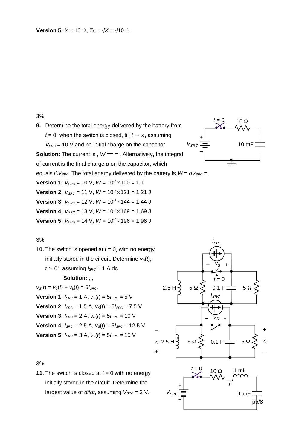
Version 5: X = 10 , Zin = -jX = -j10
3%
9.
Determine the total energy delivered by the battery from
t = 0, when the switch is closed, till t , assuming
VSRC = 10 V and no initial charge on the capacitor.
Solution: The current is , W == = . Alternatively, the integral
of current is the final charge q on the capacitor, which
equals CVSRC. The total energy delivered by the battery is W = qVSRC = .
Version 1: VSRC = 10 V, W = 10-2100 = 1 J
Version 2: VSRC = 11 V, W = 10-2121 = 1.21 J
Version 3: VSRC = 12 V, W = 10-2144 = 1.44 J
Version 4: VSRC = 13 V, W = 10-2169 = 1.69 J
Version 5: VSRC = 14 V, W = 10-2196 = 1.96 J
3%
10. The switch is opened at t = 0, with no energy
initially stored in the circuit. Determine vS(t),
t 0+, assuming ISRC = 1 A dc.
Solution: , ,
vS(t) = vC(t) + vL(t) = 5ISRC.
Version 1: ISRC = 1 A, vS(t) = 5ISRC = 5 V
Version 2: ISRC = 1.5 A, vS(t) = 5ISRC = 7.5 V
Version 3: ISRC = 2 A, vS(t) = 5ISRC = 10 V
Version 4: ISRC = 2.5 A, vS(t) = 5ISRC = 12.5 V
Version 5: ISRC = 3 A, vS(t) = 5ISRC = 15 V
3%
11. The switch is closed at t = 0 with no energy
initially stored in the circuit. Determine the
largest value of di/dt, assuming VSRC = 2 V.
p5/8
+
–
10
10 mF
VSRC
t = 0
0.1 F
t = 0
5
ISRC
5
2.5 H
+
–
vS
10
1 mH
1 mF
+
–
i
t = 0
VSRC
Solution: The largest value of di/dt occurs at t = 0, when vL = Ldi/dt = VSRC, and di/dt =
VSRC,/L = 103VSRC A/s = VSRC A/ms, where VSRC is in V.
Version 1: VSRC = 2 V, dit/dt = VSRC = 2 A/ms
Version 2: VSRC = 3 V, dit/dt = VSRC = 3 A/ms
Version 3: VSRC = 4 V, dit/dt = VSRC = 4 A/ms
Version 4: VSRC = 5 V, dit/dt = VSRC = 5 A/ms
Version 5: VSRC = 6 V, dit/dt = VSRC = 6 A/ms
3%
12. When the switch is opened at t =
0, with no energy initially stored in
the circuit, it is found that v(t) = 2t
V, t 0+ t is in s. Determine ISRC.
Solution: At t = 0+, ISRC flows in C; iC(t) = Cdv/dt = Cd(Kt)/dt = CK = CK at t = 0+. It follows
that ISRC = CK = 0.5K.
Version 1: K = 2 V/s, ISRC = 1 A
Version 2: K = 3 V/s, ISRC = 1.5 A
Version 3: K = 4 V/s, ISRC = 2 A
Version 4: K = 5 V/s, ISRC = 2.5 A
Version 5: K = 6 V/s, ISRC = 3 A
13%
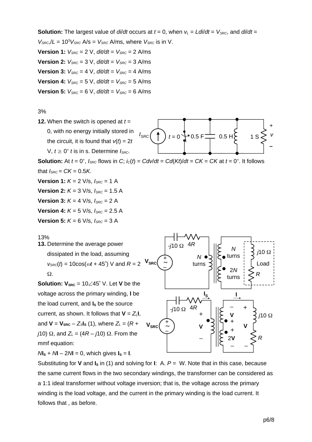
13. Determine the average power
dissipated in the load, assuming
vSRC(t) = 10cos(t + 45) V and R = 2
.
Solution: VSRC = 1045 V. Let V be the
voltage across the primary winding, I be
the load current, and IS be the source
current, as shown. It follows that V = ZLI,
and V = VSRC – ZSIS (1), where ZL = (R +
j10) , and ZL = (4R – j10) . From the
mmf equation:
NIS + NI – 2NI = 0, which gives IS = I.
Substituting for V and IS in (1) and solving for I: A. P = W. Note that in this case, because
the same current flows in the two secondary windings, the transformer can be considered as
a 1:1 ideal transformer without voltage inversion; that is, the voltage across the primary
winding is the load voltage, and the current in the primary winding is the load current. It
follows that , as before.
p6/8
+
–
v
ISRC
0.5 F
1 S
0.5 H
t = 0
R
j10
–
+
4R
-j10
VSRC
IS
I
V
+
_
V
+
_
2V
+
_
+
V
_
N
turns
2N
turns
N
turns
R
j10
Load
–
+
4R
-j10
VSRC
Version 1: R = 2 ; P = 1 W
Version 2: R = 4 ; P = 0.5 W
Version 3: R = 8 ; P = 0.25 W
Version 4: R = 10 ; P = 0.2 W
Version 5: R = 20 ; P = 0.1 W
13%
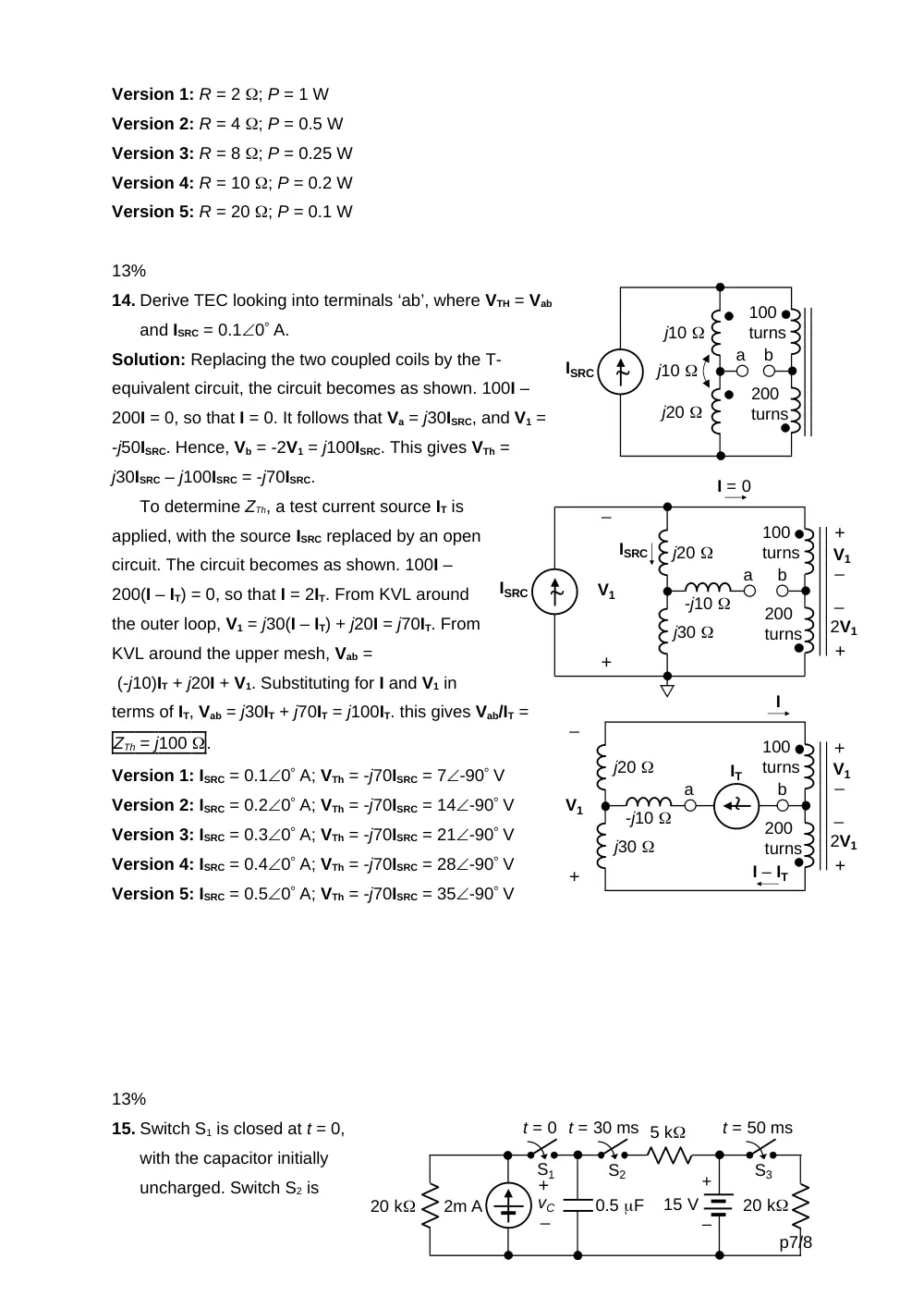
14. Derive TEC looking into terminals ‘ab’, where VTH = Vab
and ISRC = 0.10 A.
Solution: Replacing the two coupled coils by the T-
equivalent circuit, the circuit becomes as shown. 100I –
200I = 0, so that I = 0. It follows that Va = j30ISRC, and V1 =
-j50ISRC. Hence, Vb = -2V1 = j100ISRC. This gives VTh =
j30ISRC – j100ISRC = -j70ISRC.
To determine ZTh, a test current source IT is
applied, with the source ISRC replaced by an open
circuit. The circuit becomes as shown. 100I –
200(I – IT) = 0, so that I = 2IT. From KVL around
the outer loop, V1 = j30(I – IT) + j20I = j70IT. From
KVL around the upper mesh, Vab =
(-j10)IT + j20I + V1. Substituting for I and V1 in
terms of IT, Vab = j30IT + j70IT = j100IT. this gives Vab/IT =
ZTh = j100 .
Version 1: ISRC = 0.10 A; VTh = -j70ISRC = 7-90 V
Version 2: ISRC = 0.20 A; VTh = -j70ISRC = 14-90 V
Version 3: ISRC = 0.30 A; VTh = -j70ISRC = 21-90 V
Version 4: ISRC = 0.40 A; VTh = -j70ISRC = 28-90 V
Version 5: ISRC = 0.50 A; VTh = -j70ISRC = 35-90 V
13%
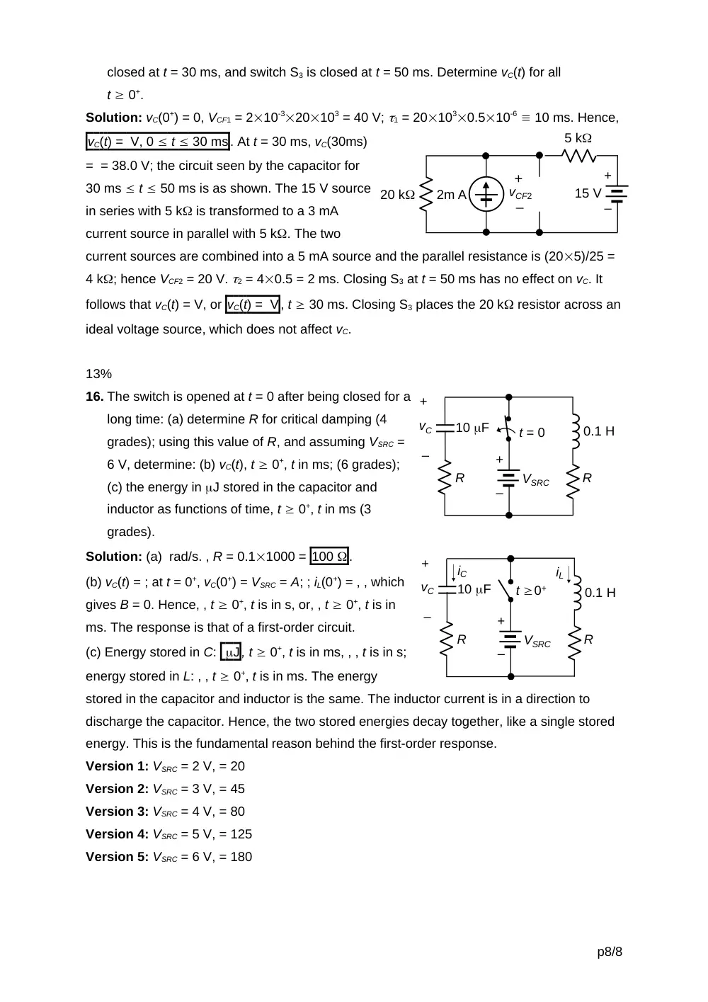
15. Switch S1 is closed at t = 0,
with the capacitor initially
uncharged. Switch S2 is
p7/8
ISRC
a
b
100
turns
200
turns
j20
j30
-j10
V1
+
_
_
2V1
+
+
ISRC
_
V1
I = 0
a
b
100
turns
200
turns
j20
j30
-j10
V1
+
_
_
2V1
+
+
_
V1
I
I – IT
IT
+
–
2m A
20 k
5 k
15 V
0.5 F
vC
+
_
t = 0 t = 30 ms
20 k
S1
S2
S3
t = 50 ms
ISRC
a
b
100
turns
200
turns
j10
j20
j10
closed at t = 30 ms, and switch S3 is closed at t = 50 ms. Determine vC(t) for all
t 0+.
Solution: vC(0+) = 0, VCF1 = 210-320103 = 40 V; 1 = 201030.510-6 10 ms. Hence,
vC(t) = V, 0 t 30 ms. At t = 30 ms, vC(30ms)
= = 38.0 V; the circuit seen by the capacitor for
30 ms t 50 ms is as shown. The 15 V source
in series with 5 k is transformed to a 3 mA
current source in parallel with 5 k. The two
current sources are combined into a 5 mA source and the parallel resistance is (205)/25 =
4 k; hence VCF2 = 20 V. 2 = 40.5 = 2 ms. Closing S3 at t = 50 ms has no effect on vC. It
follows that vC(t) = V, or vC(t) = V, t 30 ms. Closing S3 places the 20 k resistor across an
ideal voltage source, which does not affect vC.
13%
16. The switch is opened at t = 0 after being closed for a
long time: (a) determine R for critical damping (4
grades); using this value of R, and assuming VSRC =
6 V, determine: (b) vC(t), t 0+, t in ms; (6 grades);
(c) the energy in J stored in the capacitor and
inductor as functions of time, t 0+, t in ms (3
grades).
Solution: (a) rad/s. , R = 0.11000 = 100 .
(b) vC(t) = ; at t = 0+, vC(0+) = VSRC = A; ; iL(0+) = , , which
gives B = 0. Hence, , t 0+, t is in s, or, , t 0+, t is in
ms. The response is that of a first-order circuit.
(c) Energy stored in C: J, t 0+, t is in ms, , , t is in s;
energy stored in L: , , t 0+, t is in ms. The energy
stored in the capacitor and inductor is the same. The inductor current is in a direction to
discharge the capacitor. Hence, the two stored energies decay together, like a single stored
energy. This is the fundamental reason behind the first-order response.
Version 1: VSRC = 2 V, = 20
Version 2: VSRC = 3 V, = 45
Version 3: VSRC = 4 V, = 80
Version 4: VSRC = 5 V, = 125
Version 5: VSRC = 6 V, = 180
p8/8
+
–
t = 0
10 F
0.1 H
R
R
VSRC
+
–
vC
+
–
2m A
20 k
5 k
15 V
vCF2
+
_
+
–
t 0+
10 F
0.1 H
R
R
VSRC
+
–
vC
iL
iC