
EECE 210 Problems For Final -with Some Solutions, Fall 2012
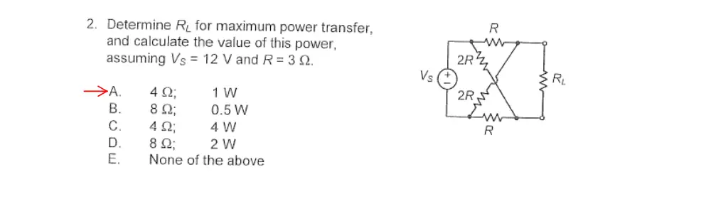
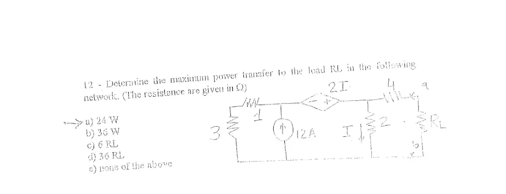
American University of Beirut · Electric Circuits · 75 pages · Dr. Fadi Karameh · with solution


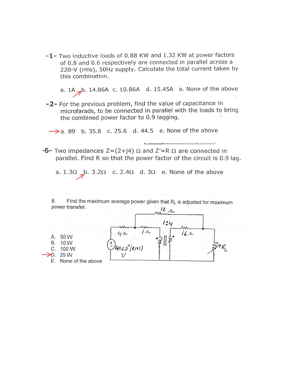

Showing the first 10 of 75 pages. Download the PDF to see all of it.
More EECE 210 files
- Final · Fall 2018Final examView
- Final · Spring 2016Final examView
- Final Exam-solution · Fall 2016Final exam · with solutionView
- Final With Solution · Fall 2014Final exam · with solutionView
- Final · Fall 2013Final examView
- Final with Solution · Fall 2011Final exam · with solutionView
- Final · Fall 2010Final examView
- Final · Fall 2009Final examView
Show the text of this final exam
I
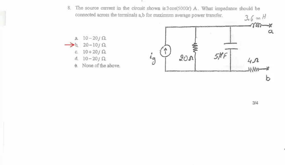
8. The source current in the circuit shown is3cos(5OUOt) A. What impedance should be
connected across the tamin& a,b for maximum average pow= transfer.
f k m H
a 1 0 - 2 0 j n
4 20-10jSL
c. 10+20jQ
d. lo-ZOjn
8. None of the above.
2
Problem 2
Find the value of the load impedance ZL such that maximum real power is delivered to it
A) 3.0 +j1.0 Ω
B) 1.75+ j0.25 Ω
C) 1.5 - j0.5 Ω
D) 3.0 + j1.1 Ω
E) None of the above
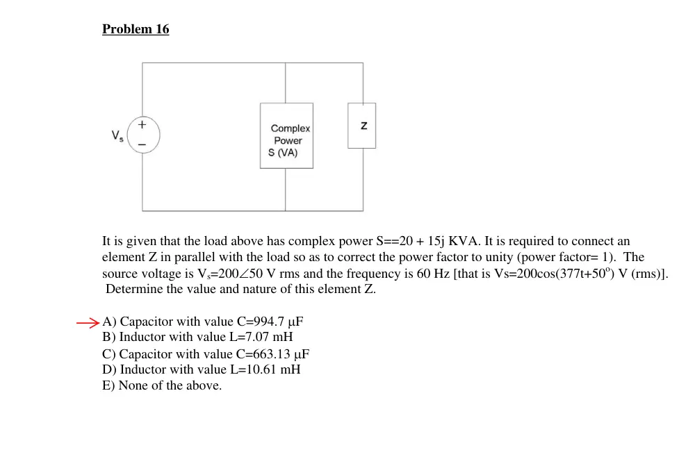
Problem 16
It is given that the load above has complex power S==20 + 15j KVA. It is required to connect an
element Z in parallel with the load so as to correct the power factor to unity (power factor= 1). The
source voltage is Vs=200∠50 V rms and the frequency is 60 Hz [that is Vs=200cos(377t+50o) V (rms)].
Determine the value and nature of this element Z.
A) Capacitor with value C=994.7 μF
B) Inductor with value L=7.07 mH
C) Capacitor with value C=663.13 μF
D) Inductor with value L=10.61 mH
E) None of the above.
1/1
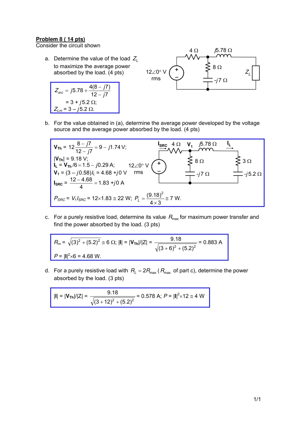
Consider the circuit shown
Problem 8 ( 14 pts)
a. Determine the value of the load
L
Z
to maximize the average power
absorbed by the load. (4 pts)
7
12
7)
4(8
5.78
j
j
j
Zsrc
−
−
+
=
= 3 + j 5.2 Ω;
ZLm = 3 – j 5.2 Ω.
b. For the value obtained in (a), determine the average power developed by the voltage
source and the average power absorbed by the load. (4 pts)
VTh =
1.74
9
7
12
7
12 8
j
j
j
−
=
−
−
V;
|VTh| = 9.18 V;
IL = VTh /6
0.29
1.5
− j
=
A;
V1 = (3 – j 0.58)IL = 4.68 +j 0 V
ISRC =
=
−
4
4.68
12
1.83 +j 0 A
PSRC = V1ISRC = 12×1.83 ≅ 22 W;
3
4
(9.18)
2
×
PL =
≅ 7 W.
c. For a purely resistive load, determine its value
Rmax
for maximum power transfer and
find the power absorbed by the load. (3 pts)
Rm =
2
2
(5.2)
(3)
+
≅ 6 Ω; |I| = |VTh|/|Z| =
2
2
(5.2)
6)
3
(
.18
9
+
+
= 0.883 A
P = |I|2×6 = 4.68 W.
d. For a purely resistive load with
RL = 2Rmax
(
Rmax
of part c), determine the power
absorbed by the load. (3 pts)
|I| = |VTh|/|Z| =
2
2
(5.2)
12)
3
(
.18
9
+
+
= 0.578 A; P = |I|2×12 ≅ 4 W
–
+
–
+
4 Ω
-j 7 Ω
8 Ω
j5.78 Ω
12∠0° V
rms
ZL
–
+
–
+
4 Ω
-j 7 Ω
8 Ω
j5.78 Ω
12∠0° V
rms
-j 5.2 Ω
3 Ω
V1
IL
ISRC
17. If a capacitor with impedance Z2 is connected in parallel to a load Z1 = 300 +j450 Ω.
What should be Z2 in ohms so that the equivalent load is purely resistive?
a) -928.6 j
b) -1112.5 j
c) -650 j
d) -750 j
e) None of the above
18. What is the power factor of the equivalent load of the previous question?
a) 0.8
b) 0.6
c) 0
d) 1
e) None of the above
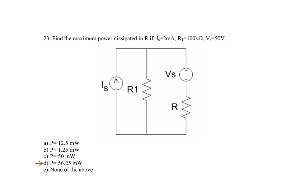
23. Find the maximum power dissipated in R if: Is=2mA, R1=100kΩ, Vs=50V.
a) P= 12.5 mW
b) P= 1.25 mW
c) P= 50 mW
d) P= 56.25 mW
e) None of the above
100 ohms
11.
assuming L = 1 H.
Determine the frequency at which maximum
–
+
L
8 Ω
10 Ω
1 F
5∠0° V
power is dissipated in the 10 Ω resistor,
Solution:
ω
ω
1 = 1
Ω. Ma
C
ximum power is
issipated in the 10 Ω resistor when XL = -XC,
d
which gives ωL = ω
1 , or
L
ω = 1 rad/s.
Add 250
ohms
3
Problem 3
Consider the periodic signal Vs(t) shown below. Assume this signal is applied to the circuit in the figure
below, find an expression for the voltage Vo(t) across the terminals a,b as shown.
A)
∑
∞
=
+
=
1
cos
2
8
( )
2
sin
n
o
m
m
o
t
n
V
V
t
V
n
n
ω
π
π
B)
∑
∞
=
+
=
1
0
cos
4
8
( )
4
sin
n
o
m
m
t
n
V
V
t
V
n
n
ω
π
π
C)
∑
∞
=
+
=
1
4
cos
2
4
( )
2
sin
n
o
m
m
t
n
V
V
t
V
n
n
ω
π
π
D)
∑
∞
=
+
=
1
4
cos
2
4
( )
2
sin
n
o
m
m
t
n
V
V
t
V
n
n
ω
π
π
E) None of the above
TF = 1/50, G(t) = 1
rms
A0=1.5, A5=1.15, B5=0
10 ohms
Derive the trigonometric form of the FSE of the waveform
shown
Solution: The function is even, and a0 = C0 =
4
4
1
A
T
A
T
=
×
×
;
∫
⎟
⎠
⎞
⎜
⎝
⎛
+
−
=
4
/
0
0
1 cos
4
4
T
n
tdt
n
T t
T
A
a
ω
=
4
/
0
0
0
0
0
0
2
2 0
1 sin
sin
4
cos
1
4
4
T
t
n
n
t
n
n
t
T
t
n
T n
T
A
⎥
⎦
⎤
⎢
⎣
⎡
−
−
−
ω
ω
ω
ω
ω
ω
⎟
⎠
⎞
⎜
⎝
⎛ −
=
⎥⎦
⎤
⎢⎣
⎡ −
=
cos 2
1
4
cos 2
1
16
2
2
2
0
2 2
π
π
π
ω
n
n
A
n
T n
A
. Hence,
⎜
⎝
⎛
+
+
+
+
=
t
t
t
A
A
f t
0
0
0
2
9 cos3
1
2 cos 2
1
cos
4
4
( )
ω
ω
ω
π
⎟
⎠
+ ...⎞
25 cos5
1
ω0t
.
f (t)
t
A
T
T/2
-T/4
T/4
Problem 9
1. in the circuit shown, each source is 15cos10t V. The
power dissipated in R is 50 W. If the frequency of one
of the sources is doubled, the power dissipated in R
is:
–
+
1 Ω
1 Ω
–
+
1 Ω
R
A. 100 W
B. 50W
C. 25 W
D. 12.5 W
E. None of the above.
Solution: The current due to each source is
1.5 cos10t
15
2
1
⎟
⎠
⎞
⎜
⎝
⎛
= 5cos10t
A. The power is
12.5
2
5
2
=
⎟⎟
⎠
⎞
⎜⎜
⎝
⎛
W. the power dissipated due to both
sources is 25 W.
2. f2(t) is the function f1(t) lowered by 1 unit, as
shown. If F1rms and F2rms are the rms values of
f1(t) and f2(t), respectively, then:
A. F1rms = F2rms
B. F1rms > F2rms
C. F1rms < F2rms
Solution: The AC components of f1(t) and f2(t) are
the same. The DC component of f1(t) is larger than that of f2(t). Hence, F1rms > F2rms.
f1(t)
t
T
f2(t)
t
T
3
2
5. The Fourier coefficients ak and bk for the periodic
function shown are:
t
v V
10π
2.5π
-2.5π
-10π
T
3T/4
T/4
T/2
A. ak = 0 for all k; bk = 0 for k odd and is non-zero
for k even
B. bk = 0 for all k; ak = 0 for k even and is non-zero
for k odd
C. bk = 0 for all k; ak = 0 for k = 0, ak = 0 for k odd
and is non-zero for k even
D. ak = 0 for all k; bk = 0 for k even and is non-zero for k odd
E. None of the above.
Solution: The function is odd, half-wave symmetric. Its average is zero; it contains no
cosine terms, only odd sine terms.
1/1
11. The current through an inductor of 1 H is
given by the periodic triangular wave. The
amplitude of the fundamental component of
the voltage across the inductor is:
t, s
-Ip
i, A
Ip
T =1/2π
A. 4Ip
B. 8Ip
C. 16Ip
D. 32Ip
E. None of the above.
Solution:
p
p
I
I
dt
L di
v
π
π
8
/ 4
1
2
1
=
= ×
=
, which is the amplitude of the square waveform
representing v. the amplitude of the fundamental is
π
π
p
p
I
I
32
8
4
=
×
.
15. The voltage and current at the terminals of a circuit are:
t V
t
v
100 sin1500
400 cos500
15
+
+
=
+
–
v
i
15 )
3cos(1500
60 )
5 sin(500
2
o
o
−
+
+
+
=
t
t
i
A
3% a) Calculate the average power delivered to the circuit.
∑
=
−
+
=
3
1
)
cos(
2
n
in
vn
m m
dc dc
V I
V I
P
θ
θ
= 15×2 +
cos( 75 )
3
100
2
1
5cos(30 )
400
2
1
o
o
−
×
×
×
+
×
×
= 934.85 W
3% b) Calculate the rms value of v.
291.93
2
(100)
2
(400)
15)
(
2
2
2
=
+
+
Vrms =
V
2% c) Calculate the rms value of i.
4.58
2
(3)
2
(5)
2)
(
2
2
2
=
+
+
Irms =
A
2/2
12. For n = 1, 2, 3,…, the function shown has:
A. an and bn nonzero for all n
B. an and bn are zero for even n
C. an and bn are zero for odd n
D. an = 0 for all n
E. bn = 0 for all n
Solution: When the dc value is removed, the ac
component has half-wave symmetry but is neither even nor odd. Hence, an and bn are
zero for even n.
f(t)
t
T
-T/2
T/2
A
A
13. Determine the total power dissipated if vI is a full-wave
rectified waveform given by: vI = 6|sin(500t)| V.
Solution:
5
10
2
100
500
1
1
5 <<
×
=
×
=
−
ωC
ohms;
π
m
dc
V
V
= 2
;
2
2
2
0.04053
10
4
m
m
dc
V
V
P
=
=
π
;
2
2
2
2
2
2
2
2
0.09472
4
2
1
;
4
2
m
m
ac
ac
m
m
V
V
V
V
V
V
⎟ =
⎠
⎞
⎜
⎝
⎛
−
=
+
=
π
π
;
5
0.09472
2
m
ac
V
P
=
;
.
0.01894 2
m
V
0.05947 2
Vm
P =
100 F
5 Ω
5 Ω
–
+
vI
14. A period of a periodic function f(t) is given by: K(4 +
2sint), 0 < t < 2π. Determine the rms value of f(t), if K =
0.5.
Solution: The square of f(t) is
(
) =
+
+
t
t
K
2
2
4sin
16sin
16
(
t
t
K
2cos2
16sin
2
2 16
−
+
+
(
2
0
2
2cos
16 sin
2
16
t
K
π
−
+ +
∫
)
)
. The area under the square is
2 ; the mean square is
36
2
K
t dt
π
=
2
2
18
2
36
K
K
=
π
π
and the rms
value is
3 2K
.
f(t)
t
π
4
2
2π
1/2
16. Derive the trigonometric Fourier expansion of the given
periodic function f(t).
1
-1
2
-2
1
2
-1
-2
t
f(t)
Solution: Since f(t) is odd, a0 = 0 = an; T = 2, ω0 = 2π/T = π; f(t) = t + 1;
∫
=
2
/
0
0 )
( )sin(
4
T
n
t dt
n
f t
T
b
ω
=
=
⎥⎦
⎤
⎢⎣
⎡∫
2
/
0
0
( )
2Im
T
jn t
dt
f t e
ω
=
⎥
⎦
⎤
⎢
⎣
⎡
+
−
1
0
0
2
0
0
0
0
0
)
(
2Im
ω
ω
ω
ω
ω
ω
jn
e
jn
e
jn
te
t
jn
t
jn
t
jn
=
⎥⎦
⎤
−
+
−
π
π
jn
n
1
1
0
2 2
⎢⎣
⎡
+
+
π
π
π
π
π
π
jn
e
n
e
jn
e
jn
jn
jn
)
(
2Im
2
⎥⎦
⎤
⎢⎣
⎡
+
−
π
π
π
n
n
n
1
2cos
2
=
(
)⎥⎦
⎤
⎢⎣
⎡
−
π
π
n
n
2cos
1 1
2
=
(
)⎥⎦
⎤
⎢⎣
⎡
−
+
)1 +1
2(
1 1
2
n
n
π
f(t) =
⎥⎦
⎤
⎢⎣
⎡
+
−
+
−
...
4
sin 4
sin3
2
sin2
2 3 sin
t
t
t
t
π
π
π
π
π
.
2/2
Problem 18
The device D in the following circuit is powered by a voltage v(t) = 2 + 2 cos(1000t) +
cos(2000t)(V ). The current across is given by i(t) = 1 + sin(1000t) + 0.5 sin(2000t)(A) find
the average power associated with D.
−
+
v(t)
D
i(t)
A) 2W
B) -2W
C) 4W
D) -4W
E) None of the above
Problem 19
The following circuit is powered by a periodic voltage source that has the following Fourier
expansion: v(t) = 21 + 20 cos(1000t) + 10 cos(2000t). Find the RMS value of the current
i(t).
−
+
v(t)
3Ω
4mH
i(t)
A) 6.68A
B) 8.14A
C) 7.3A
D) 7.6A
E) None of the above
Problem 20
For the function v(t) given below, find the value of a5. You may use the following:
�
t cos(αt) = cos(αt)
α2
+ t sin(αt)
α
.
0
1
2
3
4
5
0
1
2
t(s)
v(t)
A) 0
B) -0.0162
C) 1.27
D) -16.7
E) None of the above
The following given is used in the next 5 problems.
3 electrical elements are
powered by a 240VRMS, 60Hz source:
I
L1
I1
L2
I2
L3
I3
-
+
240VRMS∠0o
The following is given for the three elements:
L1: 240W, PF=0.6 Lag
L2: 200VARS, PF=0.5 Lag
L3: 100VA, PF=0 Lead
Problem 11
Find the total apparent power.
A) 725.67VA
B) 626.33VA
C) 550.2VA
D) 888.8VA
E) None of the above
Problem 12
Find the total power factor.
A) 0.567 Lag
B) 0.646 Lag
C) 0.808 Lag
D) 0.747 Lag
E) None of the above
Problem 13
Find the magnitude of the total current I.
A) 5.21A
B) 3.02A
C) 2.292A
D) 7.40A
E) None of the above
Problem 14
Find the capacitor that needs to be placed in parallel with the loads to adjust the power
factor to 0.9 Lag.
A) 62.7µF
B) 147µF
C) 49µF
D) 11.4µF
E) None of the above
Problem 15
Find the magnitude of I again after the power factor is adjusted as in the previous problem.
A) 1.64A
B) 3.29A
C) 0.91A
D) 2.13A
E) None of the above
C=2.74 mF
Problem 10
Find X such that the maximum power transfer constraint is satisfied.
6jΩ
−2jΩ
5jΩ
−
+ 5j(V )
−4jΩ
6jΩ
2jΩ
X
1Ω
(5 + 5j)(A)
A) 1 − 2.5jΩ
B) 1 + 2.5jΩ
C) 2 − 2.5jΩ
D) 2 + 2.5jΩ
E) None of the above
Problem 8
Find N2 and X such that maximum power is delivered to the 1000Ω resistor.
−
+
5V
10Ω
0.16jΩ
jX
1000Ω
5 : N2
A) N2 = 50, X = −16
B) N2 = 10, X = −16
C) N2 = 10, X = −0.64
D) N2 = 2, X = −0.64
E) None of the above
Problem 3
Find R that satisfies the maximum power transfer constraint.
−
+
100V
−
+
100V
10Ω
20Ω
20Ω
10Ω
20Ω
3A
R
A) 14Ω
B) 15Ω
C) 16.33Ω
D) 17.46Ω
E) None of the above
Problem 2
Find the average power associated with the 6A current source between A and B.
10jΩ
3A∠0o
B
2Ω
A
2jΩ
6A∠0o
5Ω
A) -23.86W
B) 23.86W
C) 28.71W
D) -28.71W
E) None of the above
delivered
assume rms values
7/7
8. Determine Z so that maximum power is
transferred to it and calculate this
power given that the source voltage is
10 V peak value.
s
=
ancel
peak va
h
re as shown. F
KVL: 10∠0° – 5(I + I/2) – 5(I –
I/2) = 0. Again, the terms
1
Solution: We will determine TEC as seen
by Z. On open circuit, the currents are a
shown. From KVL: 10∠0° – 5I/2 + 5I/2
VTh. In This particular problem, the
voltages across the 5 Ω resistors c
out. Hence, VTh = 10∠0° V
When Z is replaced by a s
circuit, the currents a
sc
sc
involving I cancel out. Hence, Isc
= 1∠0° A, and ZTh =
lue
ort
rom
10
1∠0
o
10 0
=
∠
o
Ω. It follows that for
aximum power transfer, Z = 10
. The power dissipated in the
load is
m
Ω
1.25
10
4
1
2
2
=
×
⎟⎟
⎠
⎞
⎜⎜
⎝
⎛
VTh
W.
–
+
10∠0° V
1:2
5 Ω
j2 Ω
5 Ω
Z
–
+
10∠0° V
5 Ω
j2 Ω
1:2
5 Ω
–
+
VTh
I
I/2
I/2
I/2
–
+
10∠0° V
j2 Ω
1:2
5 Ω
5 Ω
I
I/2
ISC – I/2
Isc
Isc + I/2
–
+
5∠0° V
R
–
+
2∠0° V
1:2
1:2
RL
10
20
R Rx =
, or
2
Rx = R
.
7. Determine the maximum power that
can be delivered to RL, assuming R
= 0.5 Ω.
Solution: The primary voltage of the
upper transformer is always 1 V. On
3/5
open circuit, the source current is zero, the primary voltage is 5 – 1 = 4 V, and VTh = 8 V. On
short circuit, the primary voltage of the lower transformer is zero, the source current is (5 –
1)/R and the short circuit current is 2/R. This gives, RTh = 4R. The maximum power delivered
is (8)2/(4×4R) = 4/R.
-j30 Ω
L
RLine
Supply
voltage
8. Given that the load L consumes 1200 W at 0.8
p.f. lagging and the magnitude of the voltage
across L is 300 V rms. Determine the power
dissipated in the resistance Rline, if Rline = 0.5 Ω.
Solution: The reactive power absorbed by the load
is
900
0.6
0.8
=
1200 ×
VAR. The reactive power absorbed by the capacitor is
3000
30
2
= −
−
V
VAR. The total complex power is 1200 + j(900 – 3000) = 1200 – j2100 VA. The magnitude of
the line current
65
300
(2100)
(1200)
2
2
=
+
A. The power dissipated in Rline is 65Rline.
4. Determine the reactive power absorbed in the circuit,
given that I = 1∠0° A rms.
Solution: The equivalent series impedance is
5
5
5
5
5
5)
5(5
j
j
j
j
j
+
=
−
+
−
. The reactive power is 5|I|2 VAR. As a
check, the current in the capacitive branch is
5
5
5
5
j
j
j
−
+
I = jI; the reactive power absorbed
by the capacitor is -5|jI|2 = -5|I|2 VAR. The current in the inductive branch is
j5 Ω
-j5 Ω
5 Ω
I
5
5
5
5
5
j
j
j
−
+
−
I = (1
– j)I =
2 ∠-45°I; the reactive power absorbed by the inductor is 5|
2
assuming VSRC = 200∠0° V rms.
I|2 = 10|I|2 VAR. The
total reactive power absorbed is 10|I|2 – 5|I|2 = 5|I|2 VAR.
5. In the circuit shown, L1 consumes
160 W at 0.8 p.f. lagging and L2
consumes 320 VAR at 0.6 p.f.
lagging. Determine I when XC is
chosen for unity power factor,
–
XC
VSRC
+
L1
L2
I
1/5
So
nce seen by the source is zero and the source applies
lution: Ay unity p.f. the total reacta
only real power. The real power consumed by L2 is
240
0.6
320
=
×
W. The total real
.8
0
power supplied by the load is 160 + 240 = 400 W. The current is
o
o
0
0
∠
=
∠
SRC
SRC
V
V
A
rms.
400
400
At
9
Problem 14
It is given that the complex power of L1 is 5+j10 VA. It is also given that L2 absorbs 20W at lagging
power factor of 0.8. What is the phase difference between I and V as shown in figure?
A) 45.00o
B) 39.81o
C) 63.33 o
D) 60.00 o
E) None of the above.
Problem 15
What is the impedance of a load if it absorbs 20KVAR at lagging power factor of 0.6 when a current of
magnitude 50 A rms flows through it?
A) 6 + 8j ohms
B) 3 + 4j ohms
C) 4+ j3 ohms
D) 8+ j6 ohms
E) None of the above.
–
+
5Ω
100∠20 Vrms
L1
L2
+
V
_
I
4. How mu& complex power is delivered by the 5630' A (rms) currd source to fhe
circuit shown in figure.
a 7.5~137.48' VA.
b. 0 VA.
C. 100 VA
d. 15.35~137.48~
VA.
e- None of the above.
and L are unknown Load 1 absorbs a complex power
absorbs a complex power of 1 0 0 ~ 4 5 ~
VA. Determine Rz
rms.