
EECE 210 Final, Fall 2009
American University of Beirut · Electric Circuits · 8 pages




More EECE 210 files
- Final · Fall 2018Final examView
- Final Exam-solution · Fall 2016Final exam · with solutionView
- Final · Spring 2016Final examView
- Final With Solution · Fall 2014Final exam · with solutionView
- Final · Fall 2013Final examView
- Problems For Final -with Some Solutions · Fall 2012Final exam · with solutionView
- Final with Solution · Fall 2011Final exam · with solutionView
- Final · Fall 2010Final examView
Show the text of this final exam
EECE 210 Final Exam fall 2009/2010 – Sections 1, 3 and 4
Closed Book – Three Hours
3%
1.
Determine the power dissipated in the circuit,
assuming I = 1 A.
Solution: The 1 Y is paralleled with a 3 , so
that it effectively becomes a 0.5 Y, and the
circuit reduces to that shown. The resistance seen
by the current source is 1||1 + 2.5 = 3 , so that
the power dissipated in the circuit is P = 3I2 W.
Version 1: I = 1 A, P = 3 W
Version 2: I = 2 A, P = 12 W
Version 3: I = 3 A, P = 27 W
Version 4: I = 4 A, P = 48 W
Version 5: I = 5 A, P = 75 W.
3%
2.
Determine the power delivered by the
3 V source, assuming = 2 V/A.
Solution: The upper node is at 5 V with
respect to the lowest node, the middle
node is at 3 V. hence, Ix = 0.5 A and the
current in the 6 resistor is also 0.5 A.
The current supplied by the 3 V source is
(3 – 0.5)/2 and the power delivered by the source is P = 1.5(3 – 0.5) = 4.5 – 0.75 W.
Version 1: = 2, P = 4.5 – 0.752 = 3 W
Version 2: = 3, P = 4.5 – 0.753 = 2.25 W
Version 3: = 4, P = 4.5 – 0.754 = 1.5 W
Version 4: = 5, P = 4.5 – 0.755 = 0.75 W
Version 5: = 6, P = 4.5 – 0.756 = 0
3%
I
1
1
1
1
1
3
3
2
2
0.5
I
1
0.5
0.5
0.5
2
0.5
–
+
–
+
–
+
10
4
6
2
5 V
3 V
10 A
Ix
Ix
–
+
40 V
5
j10
2:1
5
-j5
1:a
1/8
3.
Determine the impedance seen by the source, assuming a = 2.
Solution: Reflection of the (5 – j5) through the RH transformer gives (20 – j20) . The
impedance on the secondary side of the LH transformer is (25 – j10) . Reflected to the
primary side, this becomes (25 – j10)/a2 .
Version 1: a = 2, Z = 6.25 – j2.5
Version 2: a = 3, Z = 2.78 – j1.11
Version 3: a = 4, Z = 1.56 – j0.63
Version 4: a = 5, Z = 1 – j0.4
Version 5: a = 6, Z = 0.69 – j0.28
3%
4.
If vsrc = 10cos(1,000t) V, determine the energy
stored in the circuit in the sinusoidal steady state at
t = 0, assuming C = 1 F.
Solution: At t = 0, the voltage across C is 10 V and the
current through the inductors is zero, being
proportional to the integral of vsrc. The energy stored is
W = 50C.
Version 1: C = 1 F, W = 50 J
Version 2: C = 2 F, W = 100 J
Version 3: C = 3 F, W = 150 J
Version 4: C = 4 F, W = 200 J
Version 5: C = 5 F, W = 250 J.
3%
5.
Determine Rx given that I = 0
and R = 2 .
Solution: Since I = 0, the voltage
across Rx is 10 V, and the same
current flows through R and Rx. It
follows that , or .
Version 1: R = 2 , Rx = 1
Version 2: R = 3 , Rx = 1.5
Version 3: R = 4 , Rx = 2
Version 4: R = 5 , Rx = 2.5
Version 5: R = 6 , Rx = 3
1H
1H
k = 0.5
–
+
vsrc
C
–
+
100 V
8
6
-j5
–
+
300 V
-j10
R
Rx
I
2/8
3%
6.
Determine the power absorbed or
delivered by the dependent source
assuming R = 1 .
Solution: The current in the 2 resistor is 2Ix
flowing downwards. From KVL in the mesh on
the left, 10 = 4Ix + 2, or Ix = 2 A. The voltage
rise Vx across the dependent source is given
by: Vx – RIx = 5, or Vx = 2R + 5; The power P
delivered by the source is P = 2(2R + 5).
Version 1: R = 1 , P = 2(21 + 5) = 14 W
Version 2: R = 2 , P = 2(22 + 5) = 18 W
Version 3: R = 3 , P = 2(23 + 5) = 22 W
Version 4: R = 4 , P = 2(24 + 5) = 26 W
Version 5: R = 5 , P = 2(25 + 5) = 30 W.
3%
7.
Determine the maximum power that
can be delivered to RL, assuming R =
0.5 .
Solution: The primary voltage of the
upper transformer is always 1 V. On
open circuit, the source current is zero,
the primary voltage is 5 – 1 = 4 V, and
VTh = 8 V. On short circuit, the primary
voltage of the lower transformer is zero, the source current is (5 – 1)/R and the short circuit
current is 2/R. This gives, RTh = 4R. The maximum power delivered is (8)2/(44R) = 4/R.
Version 1: R = 0.5 , P = 4/0.5 = 8 W
Version 2: R = 1 , P = 4/1 = 4 W
Version 3: R = 2 , P = 4/2 = 2 W
Version 4: R = 2.5 , P = 4/0.8 = 1.6 W
Version 5: R = 4 , P = 4/4 = 1 W.
3%
8.
Given that the load L consumes 1200 W at 0.8
p.f. lagging and the magnitude of the voltage
–
+
10 V
R
10
2
–
+
2 V
–
+
Ix
5 V
Ix
-j30
L
RLine
Supply
voltage
–
+
50 V
R
–
+
20 V
1:2
1:2
RL
3/8
across L is 300 V rms. Determine the power dissipated in the resistance Rline, if Rline = 0.5
.
Solution: The reactive power absorbed by the load is VAR. The reactive power absorbed
by the capacitor is VAR. The total complex power is 1200 + j(900 – 3000) = 1200 – j2100
VA. The magnitude of the line current A. The power dissipated in Rline is 65Rline.
Version 1: R = 0.5 , P = 650.5 = 32.5 W
Version 2: R = 0.6 , P = 650.6 = 39 W
Version 3: R = 0.7 , P = 650.7 = 45.5 W
Version 4: R = 0.8 , P = 650.8 = 52 W
Version 5: R = 0.9 , P = 650.9 = 58.5 W.
3%
9.
Two identical coils, each having an inductance of 10 mH, are connected in series. When
the connections to one of the coils are reversed, the total inductance is multiplied by a
factor a. Determine the coupling coefficient of the coils.
Solution: (10 + 10 + 2M) = a(10 + 10 – 2M); 2M(a + 1) = 20(a – 1); ;
Version 1: a = 1.5, 0.2
Version 2: a = 1.6, 0.23
Version 3: a = 1.7, 0.26
Version 4: a = 1.8, 0.29
Version 5: a = 1.9, 0.31.
3%
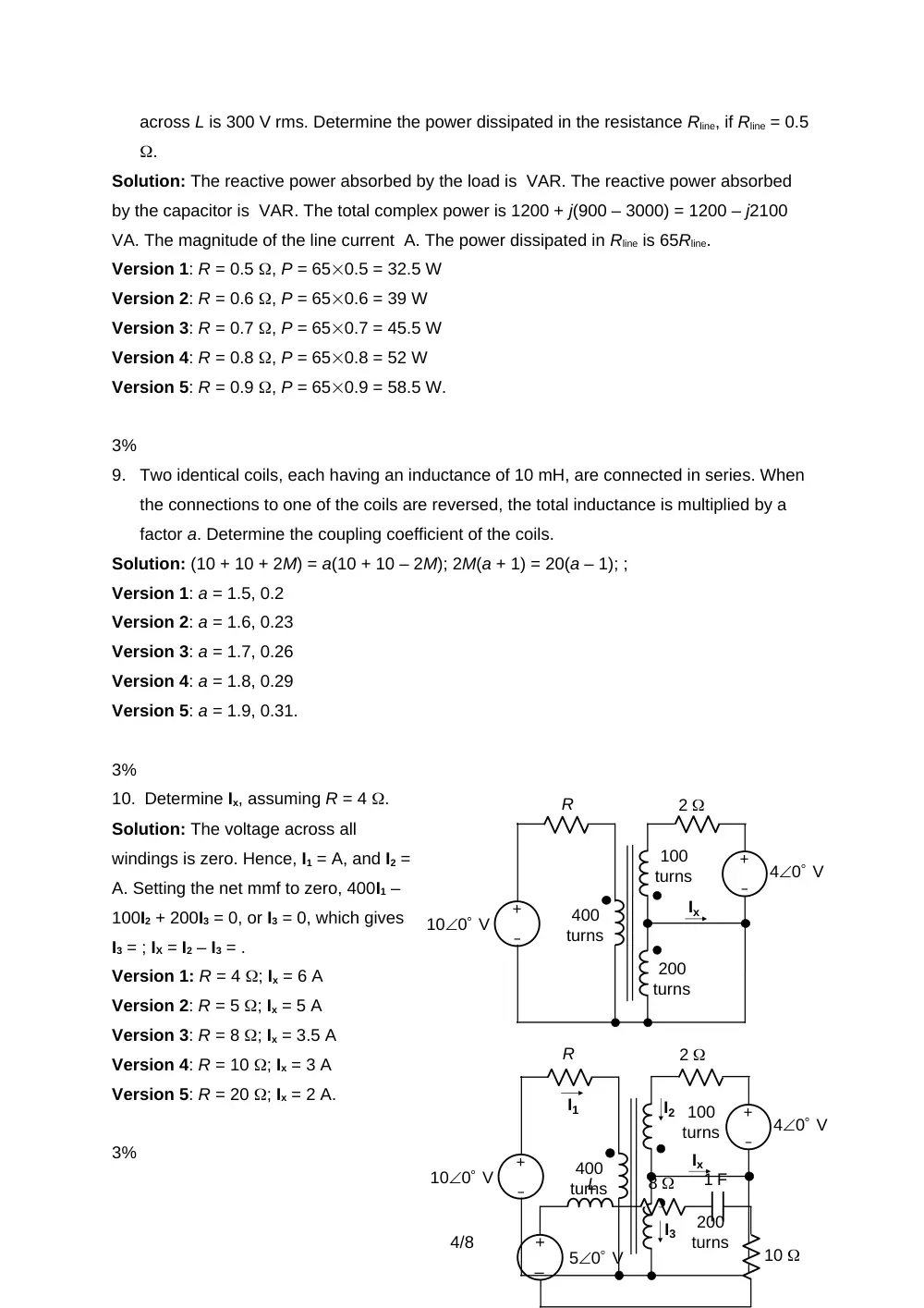
10. Determine Ix, assuming R = 4 .
Solution: The voltage across all
windings is zero. Hence, I1 = A, and I2 =
A. Setting the net mmf to zero, 400I1 –
100I2 + 200I3 = 0, or I3 = 0, which gives
I3 = ; IX = I2 – I3 = .
Version 1: R = 4 ; Ix = 6 A
Version 2: R = 5 ; Ix = 5 A
Version 3: R = 8 ; Ix = 3.5 A
Version 4: R = 10 ; Ix = 3 A
Version 5: R = 20 ; Ix = 2 A.
3%
–
+
100 V
R
2
–
+
400
turns
100
turns
200
turns
40 V
Ix
–
+
100 V
R
2
–
+
400
turns
100
turns
200
turns
40 V
Ix
I1
I2
I3
–
+
L
8
10
1 F
50 V
4/8
11. Determine the frequency at which maximum power is dissipated in the 10 resistor,
assuming L = 1 H.
Solution: . Maximum power is dissipated in the 10 resistor when XL = -XC, which gives
L = , or rad/s.
Version 1: L = 1 H; rad/s
Version 2: L = 2 H; = 0.71rad/s
Version 3: L = 3 H; = 0.58 rad/s
Version 4: L = 4 H; rad/s
Version 5: L = 5 H; = 0.45 rad/s
3%
12. For n = 1, 2, 3,…, the function shown has:
A. an and bn nonzero for all n
B. an and bn are zero for even n
C. an and bn are zero for odd n
D. an = 0 for all n
E. bn = 0 for all n
Solution: When the dc value is removed, the ac
component has half-wave symmetry but is neither even nor odd. Hence, an and bn are
zero for even n.
3%
13. Determine the total power dissipated if vI is a full-wave
rectified waveform given by: vI = 6|sin(500t)| V.
Solution: ohms; ; ; ; ; .
Version 1: Vm = 6 V, W
Version 2: Vm = 7 V, 2.91 W
Version 3: Vm = 8 V, 3.81 W
Version 4: Vm = 9 V, 4.82 W
Version 5: Vm = 10 V, 5.95 W.
3%
14. A period of a periodic function f(t) is given by: K(4 + 2sint),
0 < t < 2. Determine the rms value of f(t), if K = 0.5.
Solution: The square of f(t) is
100 F
5
5
–
+
vI
f(t)
t
T
-T/2
T/2
A
A
f(t)
t
4
2
2
5/8
. The area under the square is ; the mean square is and the rms value is .
Version 1: K = 0.5, rms = = 2.12
Version 2: K = 0.6, rms = = 2.55
Version 3: K = 0.7, rms = = 2.97
Version 4: K = 0.8, rms = = 3.39
Version 5: K = 0.9, rms = = 3.82.
3%
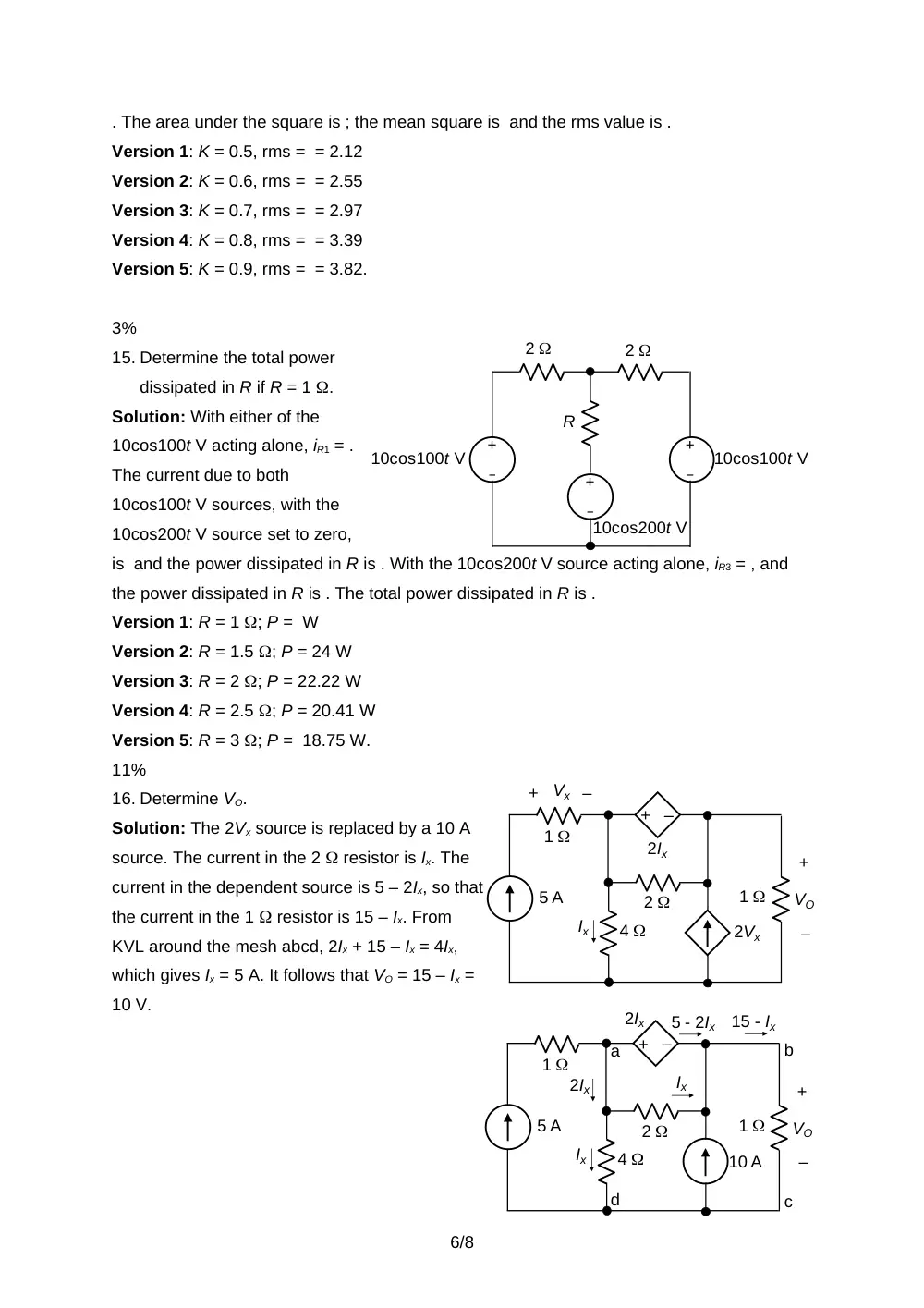
15. Determine the total power
dissipated in R if R = 1 .
Solution: With either of the
10cos100t V acting alone, iR1 = .
The current due to both
10cos100t V sources, with the
10cos200t V source set to zero,
is and the power dissipated in R is . With the 10cos200t V source acting alone, iR3 = , and
the power dissipated in R is . The total power dissipated in R is .
Version 1: R = 1 ; P = W
Version 2: R = 1.5 ; P = 24 W
Version 3: R = 2 ; P = 22.22 W
Version 4: R = 2.5 ; P = 20.41 W
Version 5: R = 3 ; P = 18.75 W.
11%
16. Determine VO.
Solution: The 2Vx source is replaced by a 10 A
source. The current in the 2 resistor is Ix. The
current in the dependent source is 5 – 2Ix, so that
the current in the 1 resistor is 15 – Ix. From
KVL around the mesh abcd, 2Ix + 15 – Ix = 4Ix,
which gives Ix = 5 A. It follows that VO = 15 – Ix =
10 V.
–
+
5 A
2Ix
2Vx
2
4
1
Ix
–
+
Vx
–
+
VO
1
2
2
–
+
R
–
+
10cos100t V
–
+
10cos100t V
10cos200t V
–
+
5 A
10 A
2
4
1
–
+
VO
Ix
5 - 2Ix
1
a
Ix
2Ix
2Ix
15 - Ix
b
d
c
6/8
11%
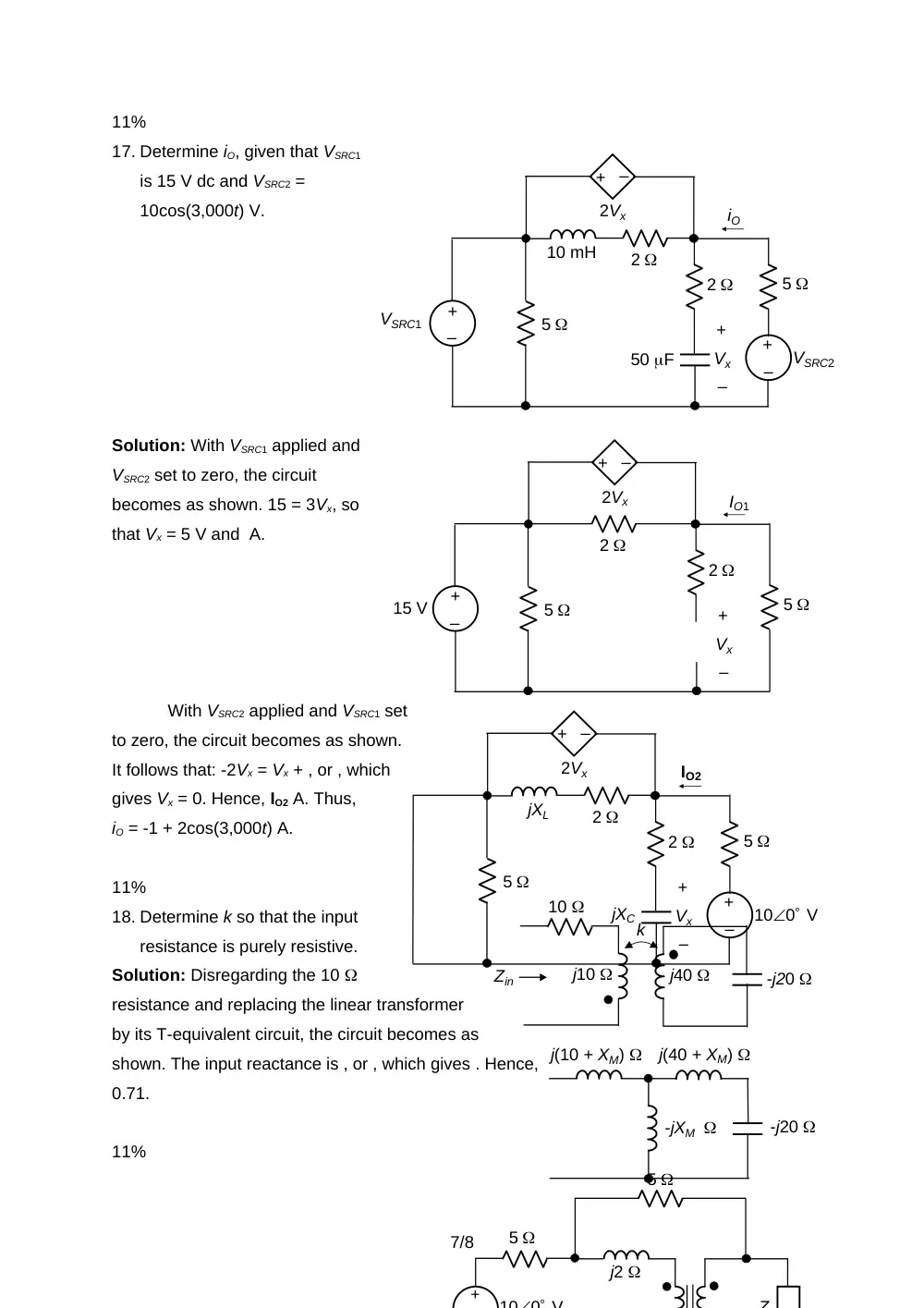
17. Determine iO, given that VSRC1
is 15 V dc and VSRC2 =
10cos(3,000t) V.
Solution: With VSRC1 applied and
VSRC2 set to zero, the circuit
becomes as shown. 15 = 3Vx, so
that Vx = 5 V and A.
With VSRC2 applied and VSRC1 set
to zero, the circuit becomes as shown.
It follows that: -2Vx = Vx + , or , which
gives Vx = 0. Hence, IO2 A. Thus,
iO = -1 + 2cos(3,000t) A.
11%
18. Determine k so that the input
resistance is purely resistive.
Solution: Disregarding the 10
resistance and replacing the linear transformer
by its T-equivalent circuit, the circuit becomes as
shown. The input reactance is , or , which gives . Hence,
0.71.
11%
–
+
2Vx
2
5
–
+
Vx
5
2
15 V
–
+
IO1
–
+
2Vx
2
5
–
+
Vx
100 V
5
–
+
2
jXL
jXC
IO2
k
j40
j10
-j20
10
Zin
-j20
j(40 + XM)
j(10 + XM)
-jXM
+
100 V
5
j2
5
Z
–
+
2Vx
2
5
–
+
Vx
VSRC2
5
–
+
2
10 mH
50 F
VSRC1
–
+
iO
7/8
19. Determine Z so that maximum power is transferred to it and calculate this power given
that the source voltage is 10 V peak value.
Solution: We will determine TEC as seen by
Z. On open circuit, the currents are as
shown. From KVL: 100 – 5I/2 + 5I/2 = VTh.
In This particular problem, the voltages
across the 5 resistors cancel out. Hence,
VTh = 100 V peak value
When Z is replaced by a short circuit,
the currents are as shown. From KVL: 100
– 5(Isc + I/2) – 5(Isc – I/2) = 0.
Again, the terms involving I cancel
out. Hence, Isc = 10 A, and ZTh =
. It follows that for maximum
power transfer, Z = 10 . The
power dissipated in the load is W.
11%
20. Derive the trigonometric Fourier
expansion of the given periodic function f(t).
Solution: Since f(t) is odd, a0 = 0 = an; T = 2, 0 = 2/T = ; f(t) = t + 1;
= = = = f(t) =.
1
-1
2
-2
1
2
-1
-2
t
f(t)
–
+
100 V
5
j2
1:2
5
–
+
VTh
I
I/2
I/2
I/2
–
+
100 V
5
j2
1:2
5
I
I/2
ISC – I/2
Isc
Isc + I/2
8/8