
EECE 340 Chapter 10, Fall 2011
American University of Beirut · Signals and Systems · 44 pages · Prof. Karim Kabalan

Showing the first 10 of 44 pages. Download the PDF to see all of it.
More EECE 340 files
Show the text of this chapter
Chapter 10
Discrete-Time Signals and
Systems
Introduction
� A discrete-time signal x(nTs) is a signal that is
only defined at discrete instants of time. A
discrete-time signal is usually derived from a
continuous time signal through sampling and
Ts is called the sampling period. Therefore,
sampling the signal x(t) at time Ts yields a
discrete-time signal x(nTs). For convenience
of presentation, we use
x[n] = x(nTs) for n = 0, ± 1, ±2, ±3, ……
Properties of a DT signal x[n]
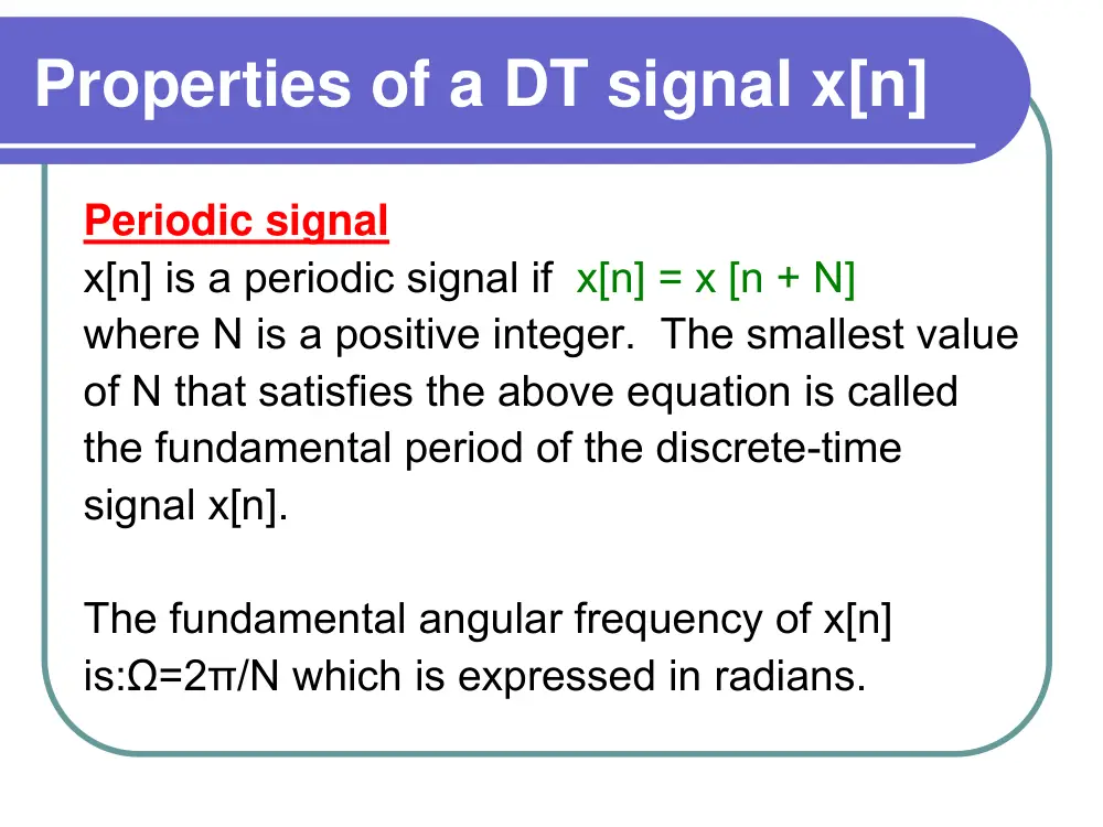
Periodic signal
x[n] is a periodic signal if x[n] = x [n + N]
where N is a positive integer. The smallest value
of N that satisfies the above equation is called
the fundamental period of the discrete-time
signal x[n].
The fundamental angular frequency of x[n]
is:Ω=2π/N which is expressed in radians.
Properties of a DT signal x[n]
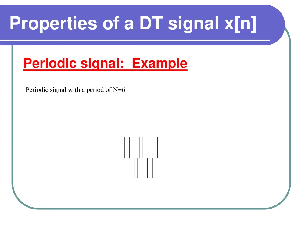
Periodic signal: Example
Periodic signal with a period of N=6
Properties of a DT signal x[n]
Periodic signal: Examples
For each of the following signals determine
whether it is periodic or not
�
x[n]=cos(2n),
Not Periodic
�
x[n]=cos(2πn),
Periodic with N=1
�
x[n]=(-1)n,
Periodic with N=2
�
x[n]=(-1)n2,
Periodic with N=2
Properties of a DT signal x[n]
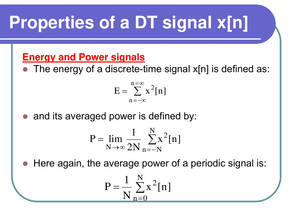
Energy and Power signals
� The energy of a discrete-time signal x[n] is defined as:
� and its averaged power is defined by:
� Here again, the average power of a periodic signal is:
∑
∞
=
=−∞
=
n
n
2
x [n]
E
∑
=−
→∞
=
N
N
n
2
N
x [n]
2N
1
lim
P
∑
=
=
N
0
n
2
x [n]
N
1
P
Properties of a DT signal x[n]
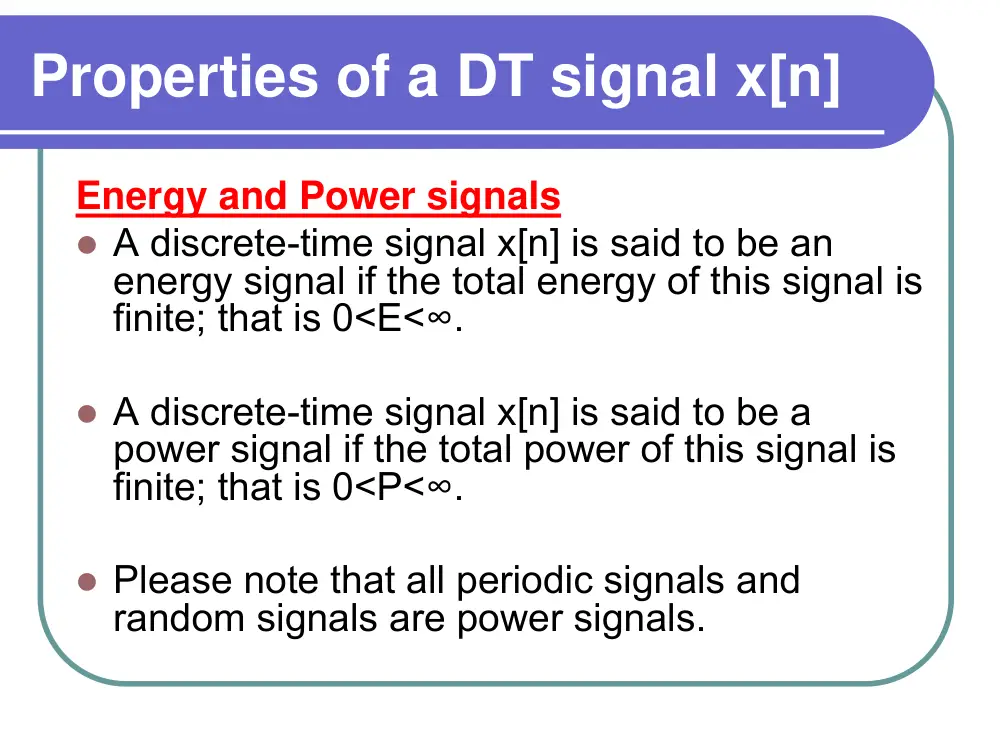
Energy and Power signals
� A discrete-time signal x[n] is said to be an
energy signal if the total energy of this signal is
finite; that is 0<E<∞.
� A discrete-time signal x[n] is said to be a
power signal if the total power of this signal is
finite; that is 0<P<∞.
� Please note that all periodic signals and
random signals are power signals.
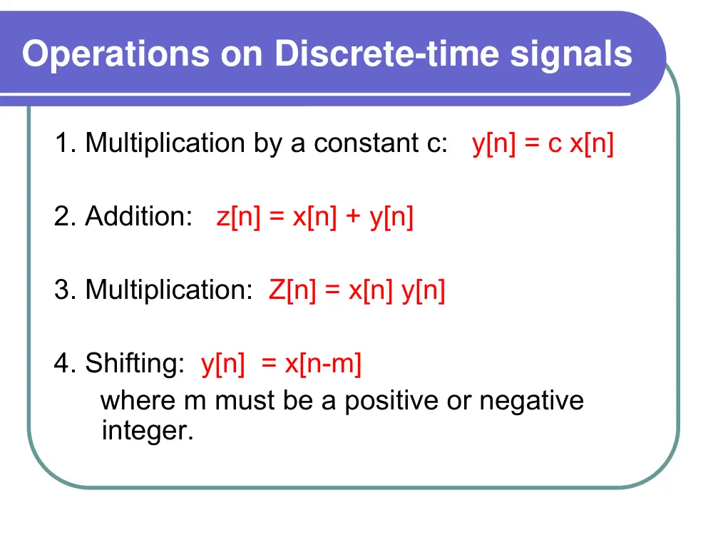
Operations on Discrete-time signals
1. Multiplication by a constant c: y[n] = c x[n]
2. Addition: z[n] = x[n] + y[n]
3. Multiplication: Z[n] = x[n] y[n]
4. Shifting: y[n] = x[n-m]
where m must be a positive or negative
integer.
Operations on Discrete-time signals
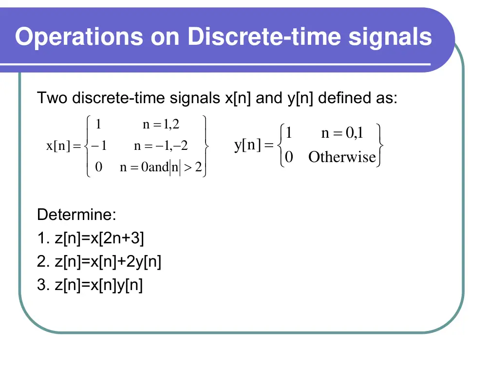
Two discrete-time signals x[n] and y[n] defined as:
Determine:
1. z[n]=x[2n+3]
2. z[n]=x[n]+2y[n]
3. z[n]=x[n]y[n]
⎪⎭
⎪⎬
⎫
⎪⎩
⎪⎨
⎧
>
=
= − −
−
=
=
2
0and n
n
0
,1 2
n
1
2,1
n
1
x[n]
⎭
⎬
⎫
⎩
⎨
⎧
=
=
Otherwise
0
1,0
n
1
[y n]
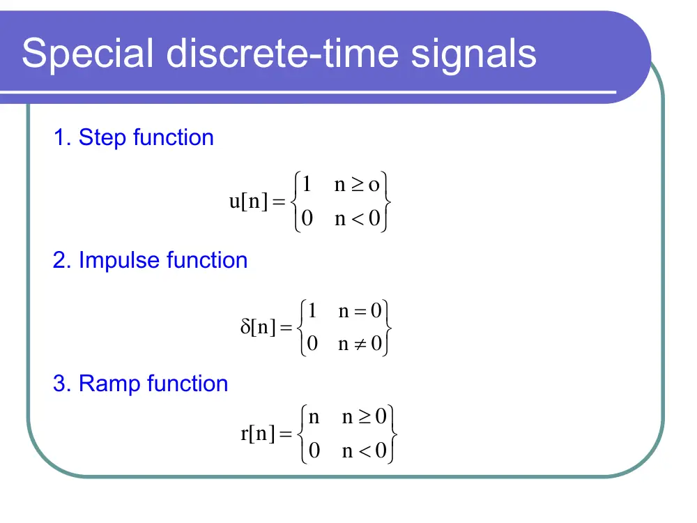
Special discrete-time signals
1. Step function
2. Impulse function
3. Ramp function
⎭
⎬
⎫
⎩
⎨
⎧
<
≥
=
0
n
0
o
n
1
[n]
u
⎭
⎬
⎫
⎩
⎨
⎧
≠
=
=
δ
0
n
0
0
n
1
n]
[
⎭
⎬
⎫
⎩
⎨
⎧
<
≥
=
0
n
0
0
n
n
[r n]
Discrete time systems
� A discrete-time system is viewed as an
interconnection of operations that
transforms an input signal into an output
signal.
� In general, the input-output relation of a
discrete time system is described by:
∑
∞
=
−
ρ
=
0
k
k
k]
x[n
[y n]
Discrete time systems: Example
(
2 )]
x[n
]1
x[n
3 x[n]
1
[y n]
−
+
−
+
=
Delay; S
Delay; S
+
x[n]
y[n]
1/3
1/3
1/3
Properties of a discrete-time system
Stable system
A discrete-time system represented by:
is said to be stable iff
∑
∞
=
−
ρ
=
0
k
k
k]
x[n
n]
[y
ρ <1
Properties of a discrete-time system
Causality
A discrete-time system is causal if the present
value of the output signal depends only on the
present or past values of the input signal
Examples
� y[n] = x[n] + x[n-1] + x[n-4] is a causal system
� y[n] = x[n+1] + x[n]+x[n-3] is not a causal
system.
Properties of a discrete-time system
Linearity
A discrete-time system is linear if the two properties
apply: Superposition and homogeneity.
Example:
y[n] = n x[n]
Properties of a discrete-time system
Time-invariant
A shift in the input corresponds to the same shift
in the output.
Example
Y[n]=nx[n]
Impulse response of a discrete-time system
� The impulse response h[n] of a discrete-
time system is easily obtained by setting
the input signal to the impulse δ[n] .
Input-output relation of an LTI system:
The convolution sum
Consider a LTI discrete-time system with input x[n] and
impulse response h[n].
The output of the signal is written as the convolution sum
The sum above is termed the convolution sum and is
denoted by the symbol *; that is,
y[n] = x[n]*h[n]
h[n]
x[n]
y[n]
∑
∞
=
−∞
=
−
=
k
k
k]
x[k]h[n
[y n]
Example
Consider the discrete-time LTI system model
representing a two-path propagation channel. If the
strength of the indirect path is a = 1/2, then
determine the output of this system if the input is:
]1
2 x[n
1
x[n]
[y n]
−
+
=
⎪
⎪
⎭
⎪⎪
⎬
⎫
⎪
⎪
⎩
⎪⎪
⎨
⎧
=
−
=
=
=
Otherwise
0
2
n
2
1
n
4
0
n
2
x[n]
Convolution Sum Evaluation Procedure
1.The first step is to determine the impulse response h[n]
2. Write x[n] as the weight sum of time shifted impulses
3. Compute h[n]*x[n].
]1
2 [n
1
[n]
h[n]
−
δ
+
δ
=
2]
2 [n
]1
4 [n
2 [n]
x[n]
−
− δ
−
+ δ
= δ
First Method
In this method, the basic definition of the convolution of
two finite causal sequences (The sequence has zero
value for negative values of n) is used with the fact that
the convolution of an M-point sequence x[n] and an N-
point sequence h[n] is an (M+N-1)-point sequence y[n].
In a mathematical form,
k ]
h[k]x[n
[y n]
M 1
N
0
k∑
−
+
=
−
=
Second Method
In this method, the convolution sum y[n] of the two finite
sequences h[n] and x[n] is given by:
y[n]= h[0]x[n]+h[1]x[n-1]+... +h[k]x[n-k]+...+h[m]x[n-m]
m is the highest index for which h[m] is different than
zero.
Third Method
This method uses the approach discussed in:
� J.W. Pierre, “A Novel Method for Calculating the
Convolution Sum of Two Finite Length Sequences”,
IEEE Transactions on Education, Vol. 39, No.1, pp.77-
80, February 1996.
Third Method
This procedure is similar to the multiplication of two
decimal numbers which makes this method attractive,
easy to learn, and simple to implement. To obtain this
table, the following steps are done:
n
0
1
2
3
4
5
k
h[k]
x[n]
2
4
-2
0
1
x[n-1]
2
4
-2
1
0.5
h[0]x[n]
2
4
-2
h[1]x[n-1]
0
1
2
-1
y[n]
2
5
0
-1
Example
The output y[n] of the four-point moving-average system is related
to the input x[n] according to the formula
→
Determine the output y[n] when the input is the rectangular pulse
defined as
x[n] = u[n] - u[n - 10]
]3
4 [n
1
2]
4 [n
1
]1
4 [n
1
4 [n]
1
h[n]
−
δ
+
−
δ
+
−
δ
+
δ
=
∑
=
−
=
3
k 0
k]
x[n
4
1
n]
[y
[n -9]
[n -8]
[n -7]
6 ]
[n
5]
[n
4]
[n
]3
[n
2]
[n
]1
[n
[n]
x[n]
+ δ
+ δ
+ δ
−
δ
+
−
+ δ
−
+ δ
−
+ δ
−
+ δ
−
+ δ
= δ
�
n
0
1
2
3
4
5
6
7
8
9
10
11
12
k
h[k]
x[n]
1
1
1
1
1
1
1
1
1
1
0
¼
x[n-1]
1
1
1
1
1
1
1
1
1
1
1
¼
x[n-2]
1
1
1
1
1
1
1
1
1
1
2
¼
x[n-3]
1
1
1
1
1
1
1
1
1
1
3
¼
h[0]x[n]
¼ ¼ ¼
¼ ¼ ¼
¼
¼
¼
¼
h[1]x[n-1]
¼ ¼
¼ ¼ ¼
¼
¼
¼
¼
¼
h[2]x[n-2]
¼
¼ ¼ ¼
¼
¼
¼
¼
¼
¼
h[3]x[n-3]
¼ ¼ ¼
¼
¼
¼
¼
¼
¼
¼
y[n]
¼ ½ ¾
1
1
1
1
1
1
1
3/4 ½
¼
Example
� In summary,
⎪
⎪
⎭
⎪⎪
⎬
⎫
⎪
⎪
⎩
⎪⎪
⎨
⎧
≤
≤
−
≤
≤
≤
≤
+
=
12
n
10
4
n
13
9
n
4
1
3
n
0
4
1
n
[y n]
Relations between LTI System
Properties and the Impulse Response
� The impulse response completely
characterizes the input-output behavior
of an LTI system. Hence, properties of
the system, such as memory, causality,
and stability, are related to the system's
impulse response. In this section, we
explore the relationships involved.
Memoryless LTI systems
� The output of a memoryless LTI system depends only on the
current input. How this property is related to h[n]?
� For an LTI system,
y[n] = h[n] * x[n] =
� For this system to be memoryless, y[n] must depend only on x[n]
and therefore cannot depend on x[n - k] for k#0. Hence, all other
terms must be zero except h[0]x[n].
� This condition implies that h[k] = 0 for k#0; thus, a discrete-time
LTI system is memoryless if and only if
where c is an arbitrary constant.
Other terms
x[n]h[0]
k]
[k]h[n
x
k
k
+
=
−
∑
∞
=
−∞
=
c [n]
h[n]
= δ
Causal LTI Systems
� The output of a causal LTI system depends only on past or
present values of the input. Again, we write the convolution sum
as:
y[n] = ... + h[-2]x[n + 2] + h[-l]x[n + 1] + h[O]x[n] + h[l]x[n - 1]
+ h[2]x[n - 2] +….
� We see that past and present values of the input, x[ n], x[n - 1],
x[n - 2],..., are associated with indices k≥ 0 in the impulse
response h[ k], while future values of the Input, x[ n + 1], x[ n + 2],
. . ., are associated with indices k < 0.
� In order, then, for y[ n] to depend only on past or present values
of the input, we require that h[k] = 0 for k < 0.
Stable LTI Systems
� An LTI DT system is stable iff the output is bounded
for every bounded input.
� A bounded output means:
When
� If we assume that the output is bounded for every
bounded input, then
M
k]
h[k]x[n
h[n] x[n]
n]
[y
k
k
<
−
=
∗
=
∑
∞
=
−∞
=
< ∞
≤
Mx
[n]
x
< ∞
≤
∑
∞
=
=−∞
x
y
k
k
M
M
h[k]
Example
A first-order DT system is described by the difference
equation y[n]=ρy[n-1]+x[n]. and has the impulse
response h[n]=ρnu[n].
1. Is this system causal?
Yes
2. Is the system memoryless?
No
3. Is it BIBO stable?
Yes if |ρ|<1.
Problem
For each of the following impulse responses, determine
whether the corresponding system is (i) memoryless, (ii)
causal, and (iii) stable. Justify your answers.
� (a) h[n] = 2nu[-n]
not memoryless, not causal, stable
� (b) h[n] =e2n u[n - 1]
not memoryless, causal, not stable
� (c) h[n] = (0.5)n u[n]
not memoryless, causal, stable
Step-response
� Step input signals are often used to characterize the response of
an LTI system to sudden changes in the input. The step response
is defined as the output due to a unit step input signal. Let h[ n]
be the impulse response of a discrete-time LTI system, and
denote the step response as s[ n]. We thus write
� That is, the step response is the running sum of the impulse
response. Note that we may invert these relationships to express
the impulse response in terms of the step response as
h[n] = s[n] - s[n - 1]
∑
∑
−∞
=
∞
=
=−∞
=
−
=
∗
=
n
k
k
k
h[k]
k]
h[k]u[n
h[n] u[n]
[s n]
EXAMPLE
Find the step response of the first-order recursive system
with impulse response
assuming that |ρ| < 1.
Answer:
u[n]
h[n]
ρn
=
u[n]
1
1
n]
[s
1
n
− ρ
− ρ
=
+
Difference Equation Representations of
LTI Systems
� Linear constant-coefficient difference equations
provide another representation for the input-output
characteristics of LTI systems. Difference equations
are used to represent discrete-time systems, while
differential equations represent continuous-time
systems. A linear constant-coefficient difference
equation has a similar form of that of continuous
system, with the derivatives replaced by delayed
values of the input x[ n ] and output y[n]:
� Examples:
An example of a second-order difference equation is
y[n] + y[n - 1] + 4y[n - 2] = x[n] + 2x[n - 1]
Solving Difference Equations
� This is best done with the use of the z-
transform discussed later.
Block Diagram Representations
� In this section, we examine block diagram representations of LTI
systems described by difference equations. A block diagram is an
interconnection of elementary operations that act on the input
signal. The block diagram is a more detailed representation of a
system than the impulse response or difference equation, on
descriptions, since it describes how the system's internal
computations or operations are ordered.
� Block diagram representations consist of an interconnection of
three elementary operations on signals:
1. Scalar multiplication: y[n] = cx[n], where c is a scalar.
2. Addition: y[n] = x[n] + w[n].
3. Time shift for that discrete-time LTI systems: y[n] = x[n - 1].
Direct Form I: Example
1. Let us rewrite the above equation in a manner similar to
that of the continuous system
2. The above equation can be written in the following form
with
2]
b x[n
]1
b x[n
b x[n]
2]
[y n
a
]1
[y n
a
[y n]
2
1
0
2
1
−
+
−
+
=
−
+
−
+
2]
b x[n
]1
b x[n
b x[n]
2]
[y n
a
]1
[y n
a
[y n]
2
1
0
2
1
−
+
−
+
+
−
−
−
−
=
w[n]
2]
[y n
a
]1
[y n
a
[y n]
2
1
+
−
−
−
−
=
2]
b x[n
]1
b x[n
b x[n]
w[n]
2
1
0
−
+
−
+
=
Direct Form I: Example
3. Draw the block diagram of the two quantities then
connect as shown below
Direct Form II: Example
We may view Direct Form I as a
cascade the of two systems: one
with input x[n] and output w[n]
and a second with input w[ n]
and output y[n]. Since these are
LTI systems, we may
interchange their order without
changing the input-output
behavior of the cascade.
State Variable representation of
Discrete LTI Systems
� We shall develop the general state-
variable description by starting with the
direct form II implementation of a
second-order LTI system. Procedure is
almost the same as for the case of a
continuous system. The output of each
time delay is denoted by a state q[n] as
shown in the next example
Example
Example: Matrix Format