
EECE 340 Chapter 11, Fall 2011
American University of Beirut · Signals and Systems · 44 pages · Prof. Karim Kabalan

Showing the first 10 of 44 pages. Download the PDF to see all of it.
More EECE 340 files
Show the text of this chapter
Chapter 11
The Z-transform
Introduction
� The z-transform is considered to be the
discrete-time counterpart to the Laplace
transform.
� With the use of the z-transform, we will
be able to obtain a broader
characterization of discrete-time LTI
systems and their interaction with
signals.
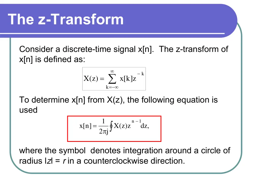
The z-Transform
Consider a discrete-time signal x[n]. The z-transform of
x[n] is defined as:
To determine x[n] from X(z), the following equation is
used
where the symbol denotes integration around a circle of
radius lzl = r in a counterclockwise direction.
∑
∞
−∞
=
−
=
k
k
x[k z]
(z)
X
dz,
2 j X( )z z
1
x[n]
n 1
∫
−
π
=
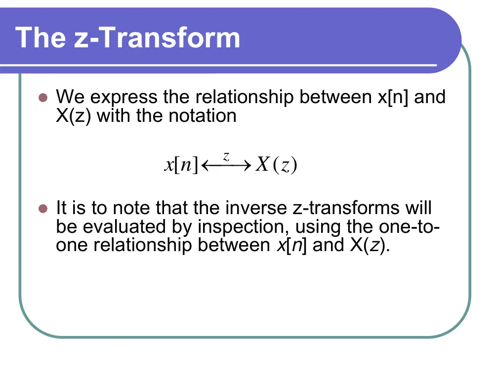
The z-Transform
� We express the relationship between x[n] and
X(z) with the notation
� It is to note that the inverse z-transforms will
be evaluated by inspection, using the one-to-
one relationship between x[n] and X(z).
( )
[ ]
X z
x n
z
⎯→
←
Convergence
� The z-transform exists when the infinite sum
in the definition converges. A necessary
condition for the convergence is absolute
summability of x[n]z-n
Since |x[n]z-n| = |x[n]r-n|, we must have
� The range of r for which this condition is
satisfied is termed the region of convergence
(ROC) of the z-transform.
< ∞
∑
∞
−∞
=
x[n r] − |
|
n
n
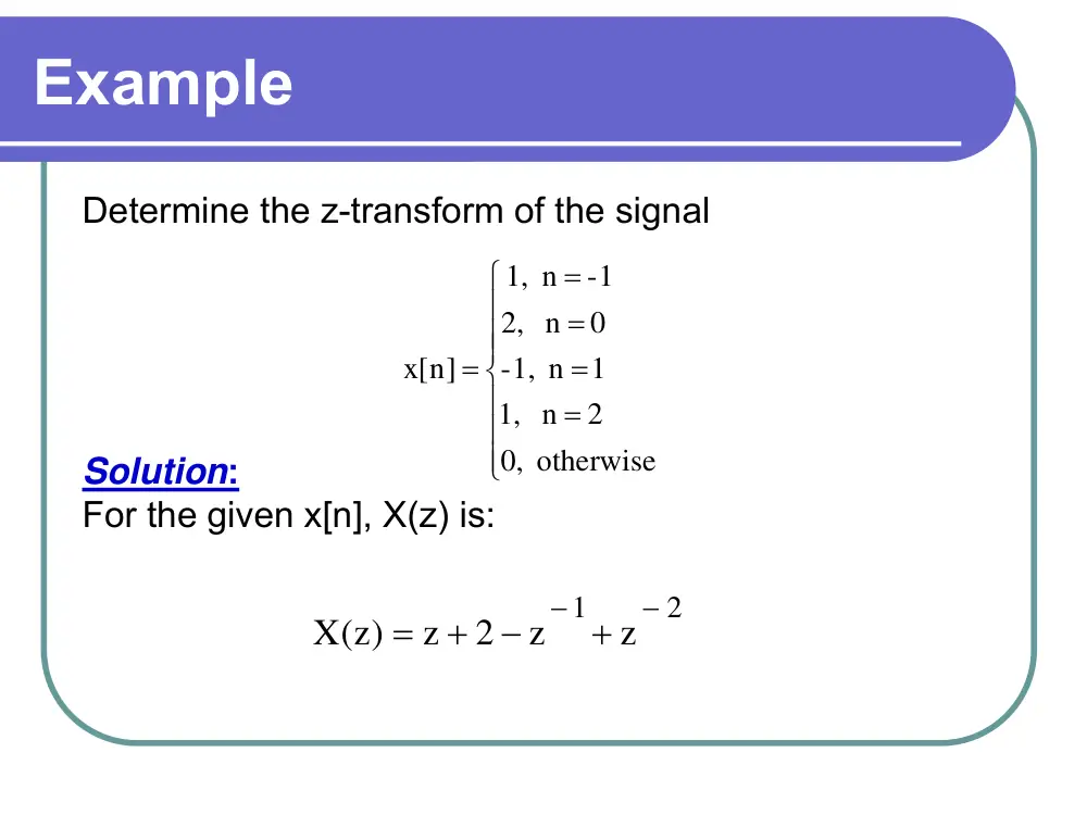
Example
Determine the z-transform of the signal
Solution:
For the given x[n], X(z) is:
⎪
⎪
⎪
⎩
⎪⎪
⎪
⎨
⎧
=
=
=
=
=
otherwise
0,
n 2
1,
-1, n 1
n 0
2,
1, n - 1
[n]
x
2
1
z
z
2
z
X(z)
−
− +
−
+
=
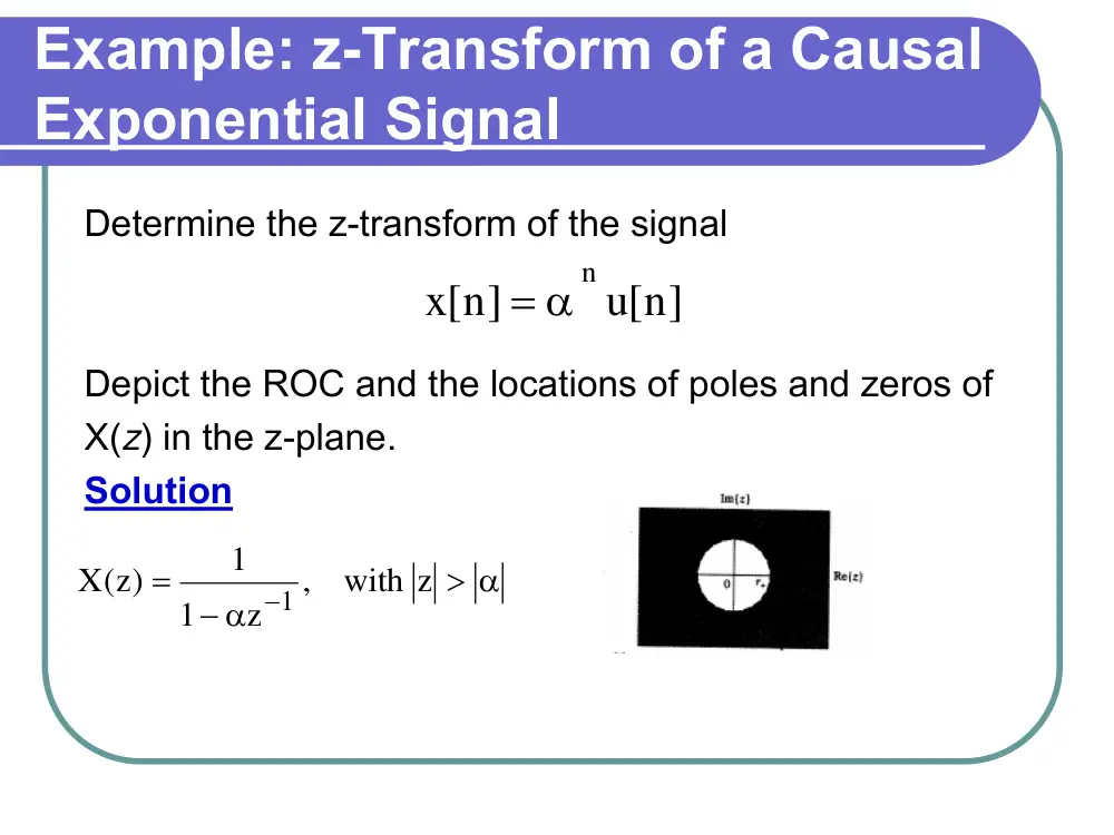
Example: z-Transform of a Causal
Exponential Signal
Determine the z-transform of the signal
Depict the ROC and the locations of poles and zeros of
X(z) in the z-plane.
Solution
u[n]
x[n]
α n
=
> α
− α
=
−
, with z
z
1
1
X(z)
1
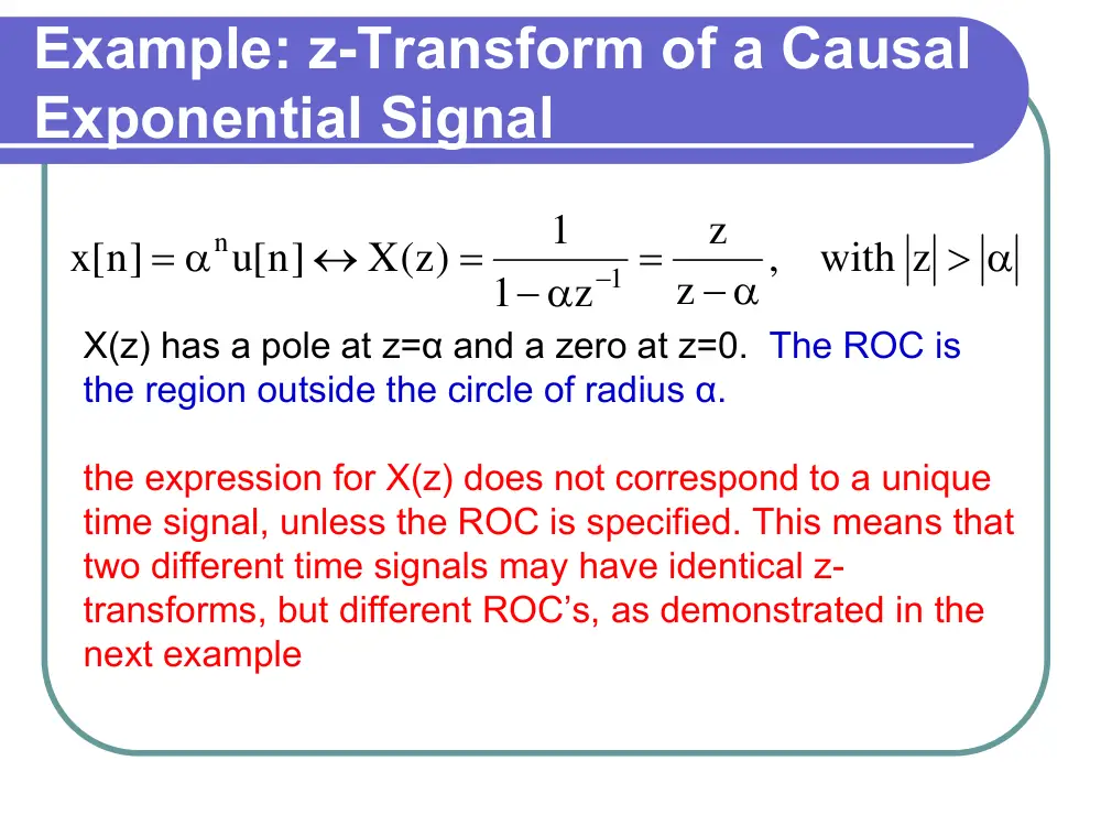
Example: z-Transform of a Causal
Exponential Signal
X(z) has a pole at z=α and a zero at z=0. The ROC is
the region outside the circle of radius α.
the expression for X(z) does not correspond to a unique
time signal, unless the ROC is specified. This means that
two different time signals may have identical z-
transforms, but different ROC’s, as demonstrated in the
next example
> α
− α
=
− α
=
↔
= α
−
, with z
z
z
z
1
1
X(z)
u[n]
x[n]
1
n
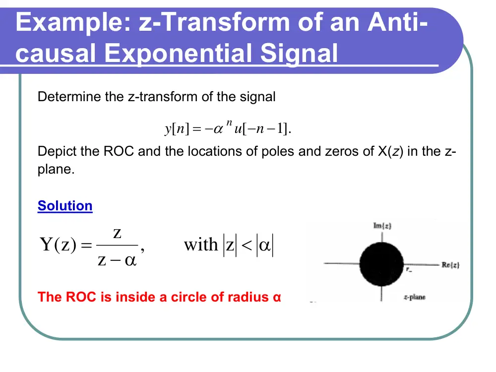
Example: z-Transform of an Anti-
causal Exponential Signal
Determine the z-transform of the signal
Depict the ROC and the locations of poles and zeros of X(z) in the z-
plane.
Solution
The ROC is inside a circle of radius α
< α
− α
=
, with z
z
z
(z)
Y
1].
[
[ ]
− −
= −
n
u
y n
α n
To conclude
� Note that Y(z) in the last two examples
are the same, except for the region of
convergence, even though the time
signals are quite different. Only the ROC
differentiates the two transforms.
� We must know the ROC to determine
the correct inverse z-transform.
� This ambiguity is a general feature of
signals that are one sided.
Example: z-transform of A Two-
Sided Signal
Determine the z-transform of
Depict the ROC and the locations of poles and zeros of X(z) in the z-
plane.
Solution:
The ROC is the plane between the 2 circles.
1
z
2
, with 1
)1
(z
z
(
(z 2z
X( )z
2 )
1
2 )
3
<
<
−
−
−
=
u[n].
2
1
]1
u[ n
x[n]
n
⎟
⎠
⎞
⎜
⎝
+ ⎛
− −
= −
Problems
Determine the z-transform and the ROC for the following signals
2
1
with z
),
)(z
z
(
)
z(2z
X(z)
u[n]
3
1
u[n]
2
1
[n]
x
3
1
2
1
6
1
n
n
>
+
−
−
=
↔
⎟
⎠
⎞
⎜
⎝
+ ⎛ −
⎟
⎠
⎞
⎜
⎝
⎛
=
3
1
with z
),
)(z
z
(
)
z(2z
X( )z
]1
u[ n
3
1
]1
u[ n
2
1
[n]
x
3
1
2
1
6
1
n
n
<
+
−
−
=
↔
− −
⎟
⎠
⎞
⎜
⎝
−⎛ −
− −
⎟
⎠
⎞
⎜
⎝
= −⎛
Problems
4
3
3
1/3), with 1
3/ 4)(
(
5/12)
(2
( )
[ ]
3
1
]1
[
4
3
[ ]
<
<
+
−
−
=
↔
⎟
⎠
⎞
⎜
⎝
+ ⎛ −
− −
⎟
⎠
⎞
⎜
⎝
= −⎛
z
z
z
z
z
X z
u n
n
u
n
x
n
n
Properties of the Z-transform
1. Linearity
x
z tranform
X(z) with ROC R
x[n]
⎯
⎯⎯⎯⎯
→
← −
y
z tranform
Y(z) with ROC R
[y n]
⎯
⎯⎯⎯
→
← −
y
x
z tranform
R
bY(z) with ROC R
aX(z)
by[n]
ax[n]
∩
+
⎯
⎯⎯⎯⎯
→
←
+
−
Example
Suppose
Determine the z-transform of ax[n]+by[n]
2
3
z
2
ROC 1
with
2
3
z
2
1
z
z
X( )z
]1
u[ n
2
3
u[n]
2
1
[n]
x
n
n
<
<
⎟⎠
⎞
⎜⎝
⎛ −
⎟⎠
⎞
⎜⎝
⎛ −
−
=
↔
− −
⎟
⎠
⎞
⎜
⎝
−⎛
⎟
⎠
⎞
⎜
⎝
⎛
=
1 2
ROC z
with
2
1
z
4
1
z
4 z
1
Y( )z
u[n]
2
1
u[n]
4
1
n]
[y
n
n
>
⎟⎠
⎞
⎜⎝
⎛ −
⎟⎠
⎞
⎜⎝
⎛ −
−
=
↔
⎟
⎠
⎞
⎜
⎝
−⎛
⎟
⎠
⎞
⎜
⎝
⎛
=
2
3
z
2
1 with ROC 1
z
1
z
4
z
b
3
z
1
z
z
a
by[n]
ax[n]
z tan sfrom
<
<
⎟⎞
⎟⎞⎜⎛ −
⎜⎛ −
2
4
2
2
⎠
⎝⎠
⎝
−
+
⎟⎞
⎟⎞⎜⎛ −
⎜⎛ −
−
⎯
⎯⎯⎯⎯
→
←
+
−
⎠
⎝⎠
⎝
2. Time Reversal
Let
Then,
x
z tranform
X(z) with ROC R
x[n]
⎯
⎯⎯⎯⎯
→
← −
x
z transform
R
z , with ROC 1
X 1
x[ n]
⎟
⎠
⎞
⎜
⎝
⎛
⎯
⎯⎯⎯⎯
→
←
−
−
3. Time shifting
Let
Then,
x
z tranform
X(z) with ROC R
x[n]
⎯
⎯⎯⎯⎯
→
← −
= ∞
=
⎯
⎯⎯⎯
→
←
−
−
−
0 or z
except possibly z
,
X(z) with ROC R
z
n ]
x[n
x
n0
z transform
0
4. Multiplication by an exponential
sequence
Let
Then,
x
z tranform
X(z) with ROC R
x[n]
⎯
⎯⎯⎯⎯
→
← −
x
z transform
n
R
X z with ROC
x[n]
α
⎟
⎠
⎞
⎜
⎝
⎛
α
⎯
⎯⎯⎯⎯
→
←
α
−
5. Convolution
Let
Then,
x
z tranform
X(z) with ROC R
x[n]
⎯
⎯⎯⎯⎯
→
← −
y
z tranform
Y( )z with ROC R
[y n]
⎯
⎯⎯⎯
→
← −
y
x
z transform
R
X(z)Y(Z) with ROC at least R
x[n]* [y n]
∩
⎯
⎯⎯⎯⎯
→
← −
6. Differentiation in the z-domain
Let
Then,
x
z tranform
X(z) with ROC R
x[n]
⎯
⎯⎯⎯⎯
→
← −
x
z transform
dz X(z) with ROC R
z d
nx[n]
−
⎯
⎯⎯⎯⎯
→
← −
Example: Applying Multiple
Properties
Find the z-transform of
Solution
⎟
⎟
⎠
⎞
⎜
⎜
⎝
⎛
−
⎟
⎠
⎞
⎜
⎝
⎟∗ ⎛
⎟
⎠
⎞
⎜
⎜
⎝
⎛
⎟
⎠
⎞
⎜
⎝
⎛ −
=
−
u[ n]
4
1
u[n]
2
1
n
x[n]
n
n
2
1
with ROC z
,
2
1
z
z
u[n]
2
1
z
n
>
+
⎯→
←
⎟
⎠
⎞
⎜
⎝
⎛ −
2
1
ROC z
with
2
1
z
2 z
1
2
1
z
z
dz
z d
u[n]
2
1
n
2
z
n
>
⎟⎠
⎞
⎜⎝
⎛ +
−
=
⎟⎟
⎟
⎟
⎠
⎞
⎜⎜
⎜
⎜
⎝
⎛
+
⎯→−
←
⎟
⎠
⎞
⎜
⎝
⎛ −
Example: Cont’d
4
1
with ROC z
,
4
1
z
z
u[n]
4
1
z
n
>
−
⎯→
←
⎟
⎠
⎞
⎜
⎝
⎛
4
z - 4 , with ROC z
- 4
4
1
z
1
z
1
u[ n]
4
1
z
n
<
=
−
⎯→
←
−
⎟
⎠
⎞
⎜
⎝
⎛
−
(
)
4
z
2
with ROC 1
,
2
1
4 z
z
2z
x[n]
2
z
<
<
⎟
⎠
⎞
⎜
⎝
⎛ +
−
⎯→
←
Inversion of the z-transform
Partial-Fraction Expansion
In most cases, the z-transform may be written as
and assume that M<N. If M>N, the we may use long division.
The partial-fraction expansion of X(z) is obtaining by factoring the
denominator of X(z) into a product of first-order terms. That is
Depending on the ROC and the order of the pole, the inverse z-
transform associated with each term in then determined by using the
appropriate transform pair
N
N
2
2
1
1
0
M
M
2
2
1
1
0
2
1
z
a
...
a z
a z
a
z
....b
b z
b z
b
P (z)
P (z)
X(z)
−
−
−
−
−
−
+
+
+
+
+
+
+
=
=
∏
=
−
−
−
−
−
+
+
+
=
=
N
1
k
1
k
0
M
M
2
2
1
1
0
2
1
)
d z
1(
a
z
....b
b z
b z
b
P (z)
P (z)
X(z)
Inversion of the z-transform
Partial-Fraction Expansion
Equations to remember
k
1
k
k
z
n
k
k
d
with ROC z
d z
1
A
A (d ) u[n]
>
−
⎯→
←
−
k
1
k
k
z
n
k
k
d
with ROC z
d z
1
A
]1
A (d ) u[ n
<
−
⎯→
←
− −
−
−
k
1 m
k
k
z
n
k
k
d
with ROC z
)
d z
1(
A
(d ) u[n]
1)!
(m
)1
m
1)...(n
(n
A
>
−
⎯→
←
−
−
+
+
−
k
m
1
k
k
z
n
k
k
d
with ROC z
)
d z
1(
A
]1
(d ) u[ n
1)!
(m
)1
m
1)...(n
(n
A
<
−
⎯→
←
− −
−
−
+
+
−
−
Example
Find the inverse z-transform of
Solution
(
)(
)
2
z
with ROC 1
z
1
2z
1
2 z
1
1
z
z
1
X(z)
1
1
1
2
1
<
<
−
⎟ −
⎠
⎞
⎜
⎝
⎛ −
+
−
=
−
−
−
−
−
(
) (
)
z
1
2
2z
1
2
2 z
1
1
1
X( )z
1
1
1
−
−
−
−
−
−
+
⎟
⎠
⎞
⎜
⎝
⎛ −
=
( )
]1
2(2) u[ n
u[n]
2 1
u[n]
2
1
x[n]
n
n
n
− −
−
−
⎟
⎠
⎞
⎜
⎝
= ⎛
Example: Inversion of an
improper rational function
Find the inverse z-transform of
Solution
where
1
with ROC z
4
2z
z
2
4
4z
10z
z
X(z)
2
2
3
<
−
−
+
−
−
=
2 zW(z);
1
X(z)
=
1
with ROC z
2z
1
3
z
1
1
3
2z
W(z)
1
1
1
<
−
−
+
+
+
= −
−
−
−
]1
2 w[n
1
x[n]
+
=
(
)
]1
3(2) u[ n
]1
u[ n
1
3 [n]
]1
2 [n
w[n]
n
n
− −
+
− −
− −
+ δ
−
= − δ
Example: Inversion using Power
series expansion
Find the inverse z-transform of
using a power series expansion
Solution
We use long division to write X(z) as a power series in z-1
since the ROC indicates that x[n] is right sided. We have
2
1
with ROC z
2 z
1
1
z
2
X(z)
1
1
>
−
+
=
−
−
.......
5.0 z
z
2z
2
X(z)
3
2
1
+
+
+
+
=
−
−
−
......
3]
[n
5.0
2]
[n
]1
2 [n
2 [n]
x[n]
+
−
δ
+
−
+ δ
−
+ δ
= δ
The Transfer Function
Consider a LTI discrete-time system whose input is x[n] and output
y[n]. The output can be expressed as the convolution of the impulse
response h[n] and the input x[n]
y[n] = x[n] * h[n]
If we take the z-transform of both sides of the equation, we will obtain
Y(z)=H(z)X(z)
H(z) is called the system transfer function which is defined as the ratio
of the z-transforms of the output to that of the input
X(z)
Y(z)
H(z)
=
The Transfer Function
X(z)
Y(z)
H(z)
=
In order to determine the impulse response of the
system (inverse z-transform), the ROC must be given.
If ROC is not known, then other system characteristics,
such as stability or causality, must be known in order
to uniquely determine the impulse response.
Example: System Identification
The problem of finding the system description from knowledge of the
input and output is known as system identification. Find the transfer
function and impulse response of a causal LTI system if the input to
the system is
and
Solution:
The z-transforms of the input and output are respectively given by:
(
)
u[n]
1/3
x[n]
n
−
=
(
)
u[n]
1/3
u[n]
)1
(3
[y n]
n
n
+
−
=
(
)
3
1
with ROC z
/3
z
1
1
X(z)
1
>
+
=
−
Example: System Identification
The transfer function of the system is:
Impulse response:
The impulse response is thus given by:
1
with ROC z
1( /3)z
1
1
z
1
3
Y(z)
1
1
>
−
+
+
=
−
−
1
with ROC z
1( /3)z )
z )(1
1(
)
1( /3)z
4 1(
H(z)
1
1
1
>
−
+
+
=
−
−
−
1
with ROC z
1( /3)z )
1(
2
z )
1(
2
H(z)
1
1
>
−
+
+
=
−
−
[ ]
2 1( /3)
[ ]
)1
2(
[ ]
u n
u n
h n
n
n
+
−
=
Example: The transfer function of an LTI
system described by a difference equation
Determine the transfer function and the impulse response for the
causal LTI system described by the difference equation.
Solution
Using the z-transform, we obtain:
The system is causal, so we choose the right-sided inverse z-
transform for each term to obtain the following impulse response:
]1
2x[n
x[n]
2]
8 [y n
3
]1
4 [y n
1
[y n]
−
+
= −
−
−
−
−
1
1
2
1
1
1 (3/ 4)
1
1( / 2)
1
2
(3/8)
1( / 4)
1
2
1
)
(
−
−
−
−
−
+ −
+
−
=
−
−
− +
=
z
z
z
z
z
z
H
u[n]
4
3
u[n]
2
1
2
[n]
h
n
n
⎟⎠
⎞
⎜⎝
+ ⎛
⎟⎠
⎞
⎜⎝
= − ⎛−
Example: Finding A Difference-
Equation Description
Find the difference- equation description of an
LTI system with transfer function
Solution
This system is described by the difference
equation
y[n] + 3y[n - 1] + 2y[n - 2] = 5x[n - 1] + 2x[n - 2].
2
3z
z
2
5z
H(z)
2
+
+
+
=
Causality and Stability
� The impulse response of a causal LTI system is zero
for n<0. Therefore, the impulse response of a causal
LTI system is determined from the transfer function by
using right-sided inverse transforms. A pole that is
inside the unit circle in the z-plane contributes an
exponentially decaying term to the impulse response,
while a pole that is outside the unit circle contributes
an exponentially increasing term.
� Therefore,
- A system is stable if the ROC includes the unit circle
- A system is stable and causal if all poles of the transfer function
are inside the unit circle.
Example: Causality and stability
An LTI system has the transfer function
Find the impulse response, assuming that the system is stable
Solution:
The given system has poles at z=-2, and
If the system is stable, then the ROC includes the unit circle. The two poles inside the
unit circle contribute right-sided terms to the impulse response, while the pole outside
the unit circle contributes a left-sided term. Hence,
1
1
j4
1
j4
2z
1
3
z
9.0 e
1
2
z
9.0 e
1
2
H(z)
−
−
− π
−
π
+
+
−
+
−
=
j4
9.0 e
z
π
=
j4
9.0 e
z
− π
=
]1
3( 2) u[ n
u[n]
9.0 e
2
u[n]
9.0 e
2
h[n]
n
n
j 4
n
j4
− −
−
−
⎟⎟
⎟
⎠
⎞
⎜⎜
⎜
⎝
⎛
+
⎟⎟
⎟
⎠
⎞
⎜⎜
⎜
⎝
⎛
=
− π
π
Example: Causality and stability
An LTI system has the transfer function
Find the impulse response, assuming that the system is causal.
Solution:
The given system has poles at z=-2, and
If the system is assumed causal, then all poles contribute right-sided terms to the
impulse response, we have
1
1
j4
1
j4
2z
1
3
z
9.0 e
1
2
z
9.0 e
1
2
H(z)
−
−
− π
−
π
+
+
−
+
−
=
j4
9.0 e
z
π
=
j4
9.0 e
z
− π
=
3( 2) u[n]
u[n]
9.0 e
2
u[n]
9.0 e
2
h[n]
n
n
j4
n
j4
−
+
⎟⎟
⎟
⎠
⎞
⎜⎜
⎜
⎝
⎛
+
⎟⎟
⎟
⎠
⎞
⎜⎜
⎜
⎝
⎛
=
− π
π
Implementing Discrete-Time LTI
Systems; Direct Form I
Example:
Consider an LTI system described by the difference equation
Taking the z-transform of this difference equation gives
2]
b x[n
]1
b x[n
b x[n]
2]
[y n
a
]1
[y n
a
[y n]
2
1
0
2
1
−
+
−
+
=
−
+
−
+
2
2
1
1
2
2
1
1
0
a z
a z
1
b z
b z
b
X(z)
Y(z)
H(z)
−
−
−
−
+
+
+
+
=
=
Implementing Discrete-Time LTI
Systems; Direct Form II
Direct Form II was obtained by simply interchanging the order of the
two systems
EXAMPLE
Consider a system represented by the transfer function
Depict the cascade form for this system, using real-valued second-order
sections. Assume that each second-order section is implemented as a direct
form II representation.
Solution:
We combine complex-conjugate poles and zeros into the sections,
obtaining
(
)(
)
)
z
.0 75e
)(1
z
.0 75e
1(
z
5.0 e
1
z
5.0 e
1
)
z
)(1
jz
)(1
jz
1(
H(z)
1
j / 8
1
j / 8
1
j / 4
1
/ 4
j
1
1
1
−
π
−
π
−
− π
−
π
−
−
−
−
−
−
−
+
−
+
=
(
2 )
1
2
1
.0 25z
cos( /4)z
1
z )
1(
H ( )z
−
−
−
+
π
−
+
=
(
2 )
1
1
2
(9/16)z
cos( /8 z)
5.1
1
)
z
1(
H ( )z
−
−
−
+
π
−
+
=
Example
Example
Depict the parallel-form representation of the transfer function
Using first-order sections implemented as a direct form II
representation.
Answer:
)
.0 25z
)(1
5.0 z
)(1
5.0 z
1(
5.0 z
5.0 z
4
H(z)
1
1
1
2
1
−
−
−
−
−
−
+
−
−
−
=
)
.0 25z
1(
2
)
5.0 z
1(
1
)
5.0 z
1(
1
H(z)
1
1
1
−
−
−
−
+
+
+
−
=
Example
Bilinear transformation
�
The bilinear transformation does a mapping from the s-
plane to the z-plane. It maps the jω axis to the unit circle,
the left-side of the complex plane to the inside of the unit
circle, and the right-side of the complex plane into the
outside of the unit circle. The mapping is done by
substituting the following into the analog transfer function.
�
where α is a scaling parameter introduced for flexibility. In
the absence of other requirements, it is often set to 1.
⎟⎠
⎞
⎜⎝
⎛
+
−
=
+
−
= α
1
z
1
z
T
2
)1
(z
)1
(z
s
Example: First-order analog filter
Consider the analog filter described by:
Applying the Bilinear Transformation with α=1, we obtain
The resulting digital filter has one simple pole at
which is located inside the unit circle.
0
b , b
s
1
H )s(
>
+
=
1
1
b z
1
b
1
1
z
1
b
1
1
H( )z
−
−
+
−
−
+
⋅
+
=
b
1
b
1
z
+
−
=