
EECE 340 Chapter 6, Fall 2011
American University of Beirut · Signals and Systems · 22 pages · Prof. Karim Kabalan
Showing the first 10 of 22 pages. Download the PDF to see all of it.
More EECE 340 files
Show the text of this chapter
Chapter 6
Filter Characteristics of LTI
Systems
Contents
� In This chapter
- Filter characteristics
- Bandwidth
- Low pass Filter
- Band-pass filter
- Ideal Filters
� We also give some examples
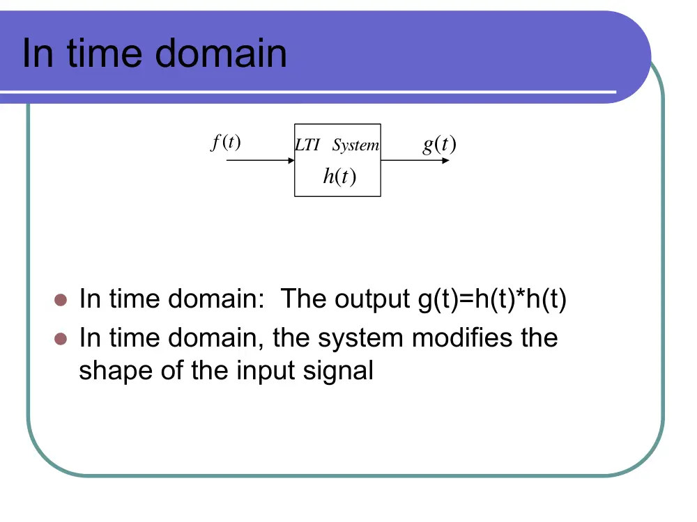
In time domain
LTI System
h t( )
f t( )
g t( )
� In time domain: The output g(t)=h(t)*h(t)
� In time domain, the system modifies the
shape of the input signal
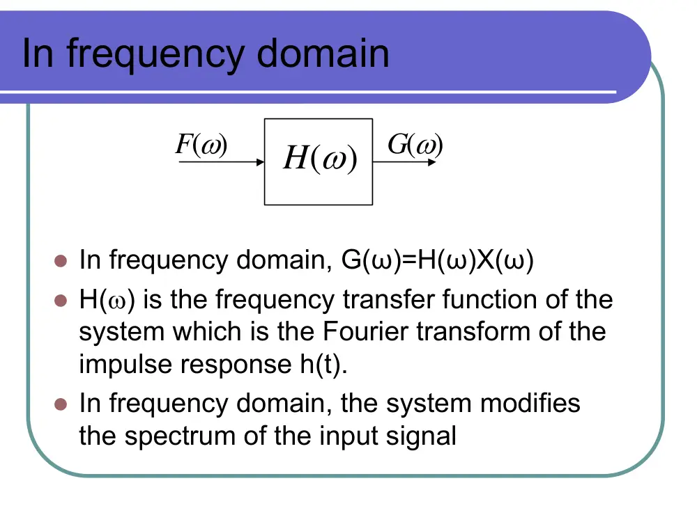
In frequency domain
H( )
ω
G( )
ω
F( )
ω
� In frequency domain, G(ω)=H(ω)X(ω)
� H(ω) is the frequency transfer function of the
system which is the Fourier transform of the
impulse response h(t).
� In frequency domain, the system modifies
the spectrum of the input signal
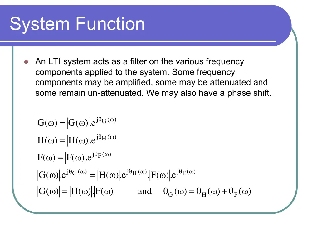
System Function
� An LTI system acts as a filter on the various frequency
components applied to the system. Some frequency
components may be amplified, some may be attenuated and
some remain un-attenuated. We may also have a phase shift.
( )
( )
( )
.) F( ) and
H(
( )
G
e.)
.F(
e.)
H(
e.)
(
G
e.)
F(
( )
F
e.)
H(
( )
H
e.)
G(
( )
G
F
H
G
j F( )
j H ( )
G ( )
j
F( )
j
H ( )
j
G ( )
j
ω
ω + θ
ω = θ
θ
ω
ω
=
ω
ω
ω
=
ω
ω
=
ω
ω
=
ω
ω
=
ω
ω
θ
ω
θ
ω
θ
ω
θ
ω
θ
ω
θ
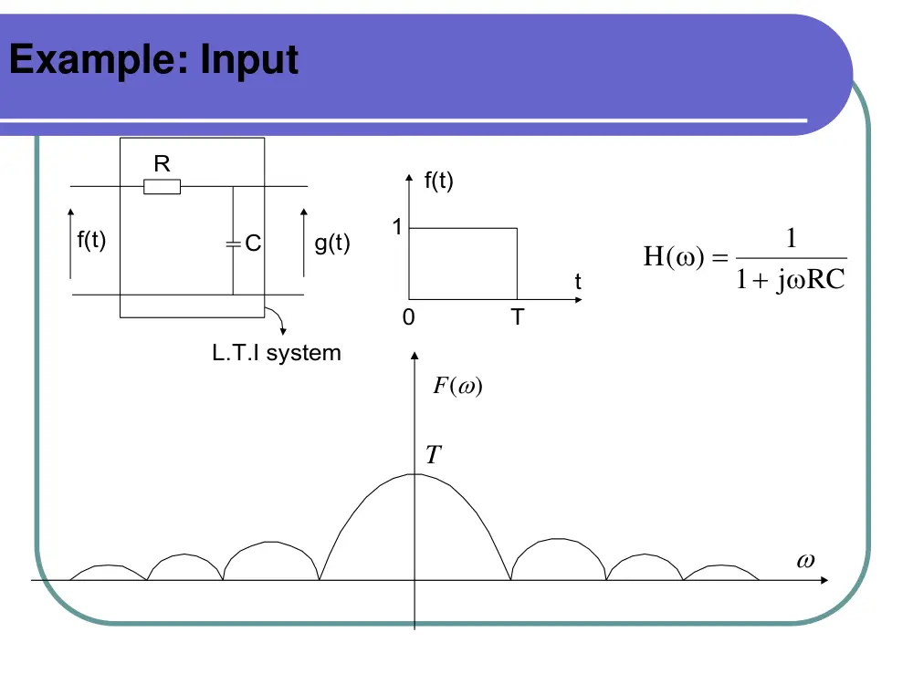
Example: Input
R
C
f(t)
g(t)
L.T.I system
f(t)
t
T
1
0
j RC
1
1
H( )
+ ω
=
ω
F( )
ω
ω
T
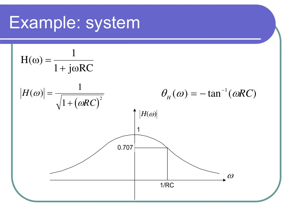
Example: system
j RC
1
1
H( )
+ ω
=
ω
(
)
H
RC
( )
ω
ω
=
+
1
1
2
θ
ω
ω
H
RC
( )
tan (
)
= −
−1
H( )
ω
ω
1
1/RC
0.707
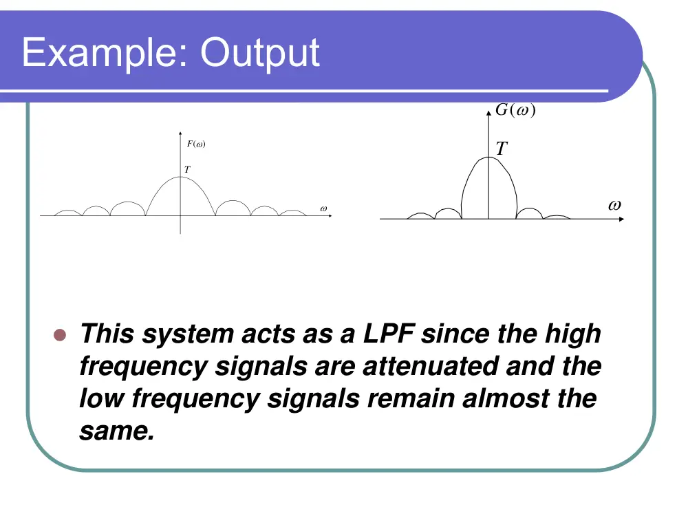
Example: Output
� This system acts as a LPF since the high
frequency signals are attenuated and the
low frequency signals remain almost the
same.
F( )
ω
ω
T
G(
)
ω
ω
T
Bandwidth
� Bandwidth is a measure of frequency range in
Hertz, of a signal or system.
� Communication signal bandwidth is the (positive)
range of frequencies occupied by a modulated
carrier wave
� Only the positive frequency plane is counted. Do not
count the symmetric negative frequency plane.
� If considering the frequency range where a
signal’s FT is non-zero, then many practical
systems occupies infinite bandwidth � this is no
good
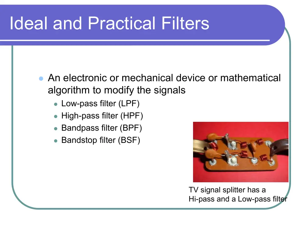
Ideal and Practical Filters
� An electronic or mechanical device or mathematical
algorithm to modify the signals
� Low-pass filter (LPF)
� High-pass filter (HPF)
� Bandpass filter (BPF)
� Bandstop filter (BSF)
TV signal splitter has a
Hi-pass and a Low-pass filter
Gain of the filter
� The gain of the system is denoted by
α(ω)=|H(ω)|. The decibels unit is usually
used for the gain
H( )
20.log
)
(
10
ω
α′ ω =
Bandwidth of a Low Pass Filter
The bandwidth of a LP system is defined as the positive
frequency components at which the amplitude response
|H(ω)| is 1/√2 times the value at zero frequency or the
frequency at which the gain drops by 3 dB below its
value at zero frequency.
Example
H( )
ω
ω
A/ 2
A
W
BW
20
0
20
0
2
20
0
20
0
20
2
3
0
10
10
10
10
10
.log
( )
.log
( )
?
.log
( )
.log
( )
.log
( )
H
H
db
H
H
db
where
H
A
−
=
⇒
−
−
≈
=
Spectrum of a Voice signal
Bandwidth of a band-pass system (filter)
� For a band-pass system (filter), the bandwidth is defined as the
range of positive frequencies over which the amplitude
response |H(ω)|remains within 1/√2 times its value at the mid-
band frequency
� ωu=upper frequency, ωM=middle frequency, and ωL=Lower
frequency
ωM
− ω M
H( )
ω
ω
ωU
ω L
−ωL
−ωU
1
2
/
1
Bandwidth
U
L
=
ω −
ω
� Ideal low-pass filter
� Magnitude response has ideal (sharp) stopband, has
ideal bandwidth f0 .
� Every frequency lower than f0 can pass, others can not.
� Phase response can have linear phase response or
non-linear phase response
� The non-ideal (practical) filter response may look like
(f)
−f0
f0
0
|H(f)|
f
f
θ
(f)
−f0
f0
0
|H(f)|
f
f
θ
Ideal filter is a very
useful tool for
analyzing
communication
systems.
Ideal Band-pass filter
� An ideal filter passes without distortion all frequency
components between its lower frequency and its upper
frequency. Outside this range, the ideal filter is assumed to
have zero magnitude
2
f
|H(f)|
0 f1
f2
−f1
−f
Impulse response of an ideal low-pass filter:
As h(t)#0 for t<0 Therefore the ideal low-pass filter is not a causal system.
⎭
⎬
⎫
⎩
⎨
⎧
< ω <
−
ω = − ω
θ
⎭
⎬
⎫
⎩
⎨
⎧
< ω <
−
=
ω
ω
=
ω
ω
θ
Otherwise
0
W
W
t.
( )
and
Otherwise
0
W
W
1
( )
H
e.)
H(
( )
H
0
H
H ( )
j
t)]
W Sa [W t(
)t(
h
0 −
π
=
h t( )
t
W/π
t0
Impulse Response of a band-pass
filter
� Left for you to do
Example: Determine the spectrum of y(t).
y t( )
sinω0t
r t
1( )
r t
2( )
r t
3( )
r t
4( )
r t
5( )
r t
6( )
cosω0t
sinω1t
cosω1t
x t( )
BPF
BW
W
@ω0
2
=
BPF
BW
W
@ω0
2
=
X( )
ω
ω
W
−W
1
×
×
×
×
×
Example: Determine the spectrum of z(t)
H1( )
ω
H2( )
ω
H1( )
ω
H2( )
ω
cos120πt
cos120πt
x t( )
y t( )
×
×
∑
∑
z t( )
1
2
3
4
5
6
5π
−5π
115π
120π
125π
X( )
ω
−125π −120π −115π
Given
H1( )
ω
ω
ω
H2(
)
ω
115π
120π
125π
−120π
5π
− 5π
1
1