
EECE 340 Chapter 7, Fall 2011
American University of Beirut · Signals and Systems · 43 pages · Prof. Karim Kabalan

Showing the first 10 of 43 pages. Download the PDF to see all of it.
More EECE 340 files
Show the text of this chapter
Chapter 7
Application of the Fourier Transform
Amplitude Modulation
Overview of Continuous Modulation
�
The purpose of a communication system is to transmit
information-bearing signals or base-band signals through
a communication channel separating the transmitter from
the receiver.
�
The term base-band is used to designate the band of
frequencies representing the message signal.
�
The voice signal has a maximum frequency component
of 3.3 KHz where the carrier frequency ƒc is
540<ƒc<1600 KHz
�
A shift of the range of frequencies in a signal is
accomplished by using modulation which is defined as
the process by which some characteristic of the carrier
is varied in accordance with a modulating wave.
Overview of Continuous Modulation
�
Modulating signal: another name for the message
signal, or the signal to be modulated
�
Modulated signal: the signal to be transmitted, or the
signal obtained after modulation
What is modulation?
�
Change baseband signal into passband signal (shift
frequency of message signal from low to high)
�
Change some characteristics of a carrier according to a
message signal
�
Add the message information into the carrier
φ( )t
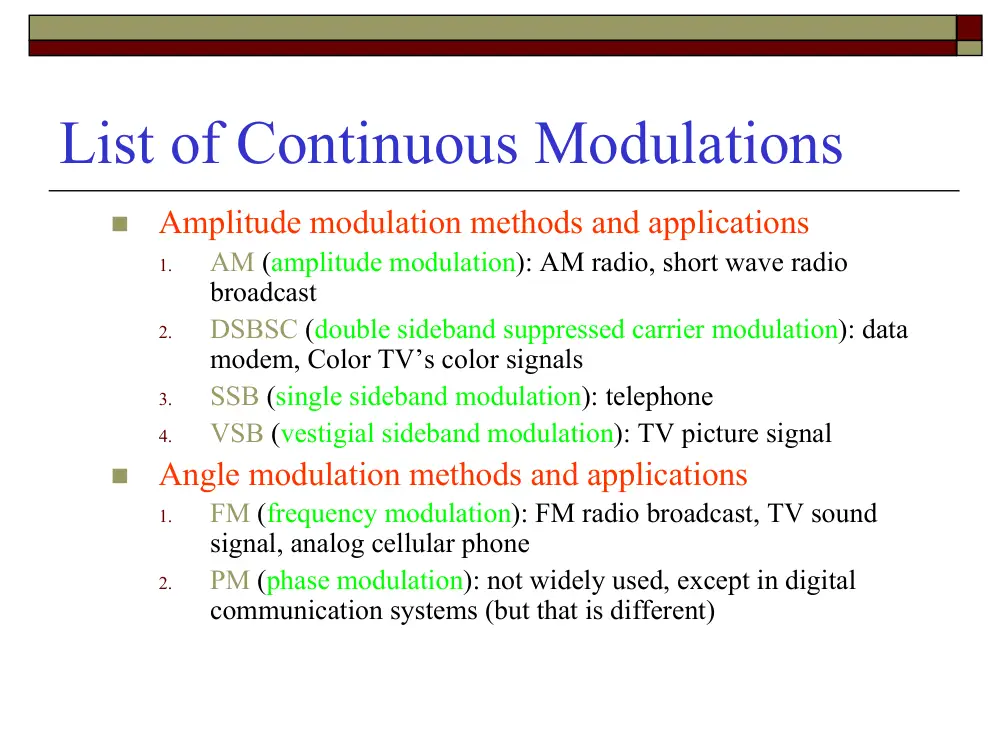
List of Continuous Modulations
�
Amplitude modulation methods and applications
1.
AM (amplitude modulation): AM radio, short wave radio
broadcast
2.
DSBSC (double sideband suppressed carrier modulation): data
modem, Color TV’s color signals
3.
SSB (single sideband modulation): telephone
4.
VSB (vestigial sideband modulation): TV picture signal
�
Angle modulation methods and applications
1.
FM (frequency modulation): FM radio broadcast, TV sound
signal, analog cellular phone
2.
PM (phase modulation): not widely used, except in digital
communication systems (but that is different)
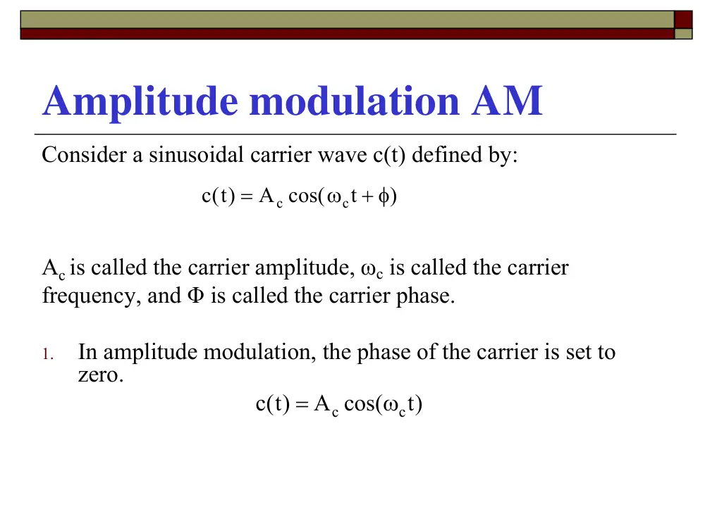
Amplitude modulation AM
Consider a sinusoidal carrier wave c(t) defined by:
Ac is called the carrier amplitude, ωc is called the carrier
frequency, and Φ is called the carrier phase.
1.
In amplitude modulation, the phase of the carrier is set to
zero.
)
t
A cos(
)t(
c
c
c
+ φ
ω
=
)t
A cos(
)t(c
c
c
ω
=
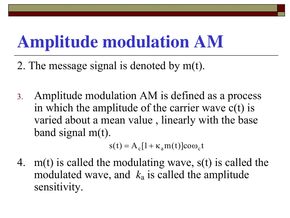
Amplitude modulation AM
2. The message signal is denoted by m(t).
3.
Amplitude modulation AM is defined as a process
in which the amplitude of the carrier wave c(t) is
varied about a mean value , linearly with the base
band signal m(t).
4. m(t) is called the modulating wave, s(t) is called the
modulated wave, and ka is called the amplitude
sensitivity.
t
m t( )]co
A 1[
)t(s
c
a
c
ω
+ κ
=
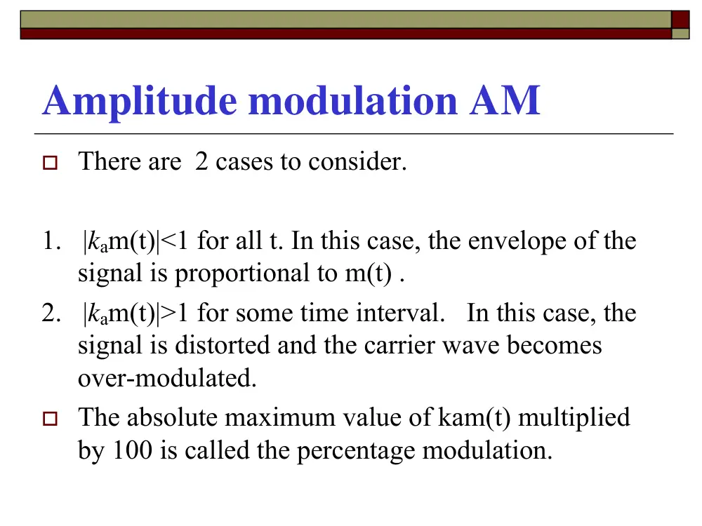
Amplitude modulation AM
� There are 2 cases to consider.
1. |kam(t)|<1 for all t. In this case, the envelope of the
signal is proportional to m(t) .
2. |kam(t)|>1 for some time interval. In this case, the
signal is distorted and the carrier wave becomes
over-modulated.
� The absolute maximum value of kam(t) multiplied
by 100 is called the percentage modulation.
� Compare carrier frequencies,
and over-modulation
f
M(f)
M(0)
W
−W
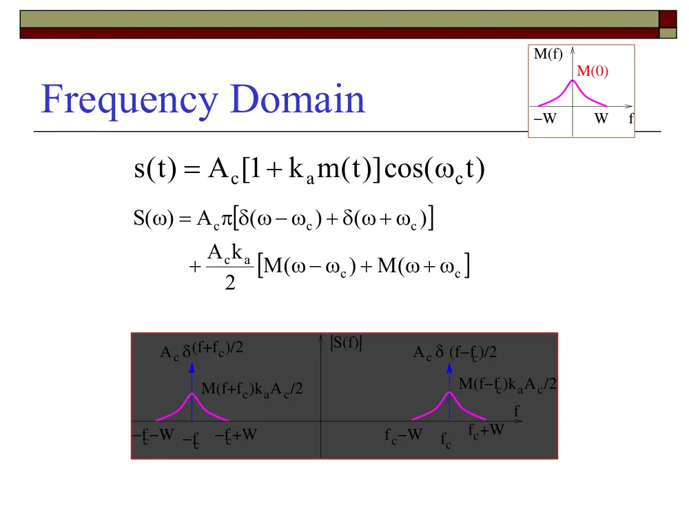
Frequency Domain
)t
k m t( )]cos(
A 1[
)t(s
c
a
c
ω
+
=
[
]
[
c ]
c
a
c
c
c
c
M(
)
M(
2
A k
)
(
)
(
A
( )
S
ω+ ω
+
ω− ω
+
+ δ ω+ ω
π δ ω− ω
=
ω
/2
f
|S(f)|
δ(f+fc)/2
M(f+fc)kaAc/2
−fc
−fc+W
−fc−W
fc
fc+W
fc−W
Ac
Ac δ (f−fc)/2
M(f−fc)kaAc
f
M(f)
M(0)
W
−W
Observations
/2
f
|S(f)|
δ(f+fc)/2
M(f+fc)kaAc/2
−fc
−fc+W
−fc−W
fc
fc+W
fc−W
Ac
Ac δ (f−fc)/2
M(f−fc)kaAc
�
The bandwidth of the AM signal is 2W (twice the bandwidth of
the message signal)
�
For positive frequencies, the portion of the spectrum of an AM
wave lying above is called upper sideband (USB) . The other
portion is the lower sideband (LSB).
�
Large Carrier (to be shown later)
�
Or this reason, it is also called Double Side-Band Large Carrier
(DSBLC)
Example: Single-tone modulation
� In this case, we assume that m(t)=amcos(ωmt)
� The corresponding AM wave is given by:
� Let kaam=µ<1 be the modulation factor
)t
t)]cos(
cos(
k a
A 1[
)t(s
c
m
m
a
c
ω
ω
+
=
)t
t)]cos(
cos(
A 1[
)t(s
c
m
c
ω
ω
+ µ
=
Example: Single-tone modulation
)t
t)]cos(
cos(
A 1[
)t(s
c
m
c
ω
ω
+ µ
=
�
Let Amax denotes the maximum value of the envelope of s(t)
�
Let Amin denotes the minimum value of the envelope of s(t)
� From the above equation, Amax = Ac [1+µ] and
Amin = Ac [1-µ]. That is :
� µ is also called the modulation index of the
waveform.
min
max
min
max
A
A
A
A
+
−
µ =
Example: Single-tone modulation
Frequency Domain
)t
t)]cos(
cos(
A 1[
)t(s
c
m
c
ω
ω
+ µ
=
)t
)t cos(
cos(
A
)t
A cos(
)t(s
c
m
c
c
c
ω
ω
µ
+
ω
=
t)
2 cos(
A
)t
2 cos(
A
)t
A cos(
)t(s
m
c
c
m
c
c
c
c
ω − ω
µ
+
ω + ω
µ
+
ω
=
[
]
⎥⎦
⎤
⎢⎣
⎡
+ δ ω+ ω − ω
δ ω− ω + ω
+
+ δ ω+ ω + ω
µ δ ω− ω − ω
+
+ δ ω+ ω
π δ ω− ω
=
ω
m
c
m
c
m
c
m
c
c
c
c
c
(
)
(
)
(
)
(
4
A
)
(
)
(
A
( )
S
The transmission bandwidth is: 2ωm rad/s
m
ω
rad/s
Carrier and sideband power in AM
�
By definition, the average power of s(t) across 1Ω Resistor is
given by:
Carrier Upper sideband Lower Sideband
power power
power
)t
t)]cos(
cos(
A 1[
)t(s
c
m
c
ω
ω
+ µ
=
t)
2 cos(
A
)t
2 cos(
A
)t
A cos(
)t(s
m
c
c
m
c
c
c
c
ω − ω
µ
+
ω + ω
µ
+
ω
=
2
2
A
2
2
A
2
(A )
P
2
c
2
c
c 2
⎟⎠
⎞
⎜⎝
⎛
µ
⎟⎠ +
⎞
⎜⎝
⎛
µ
+
=
Power ratio
� An important measure in AM is the ratio of
sideband power to the total power. For a
single-tone modulation, this ratio, X, is given
by:
� X is dependent only on the modulation factor
µ
2 .
2
1
2
A
4
1
2
A
A
4
1
X
2
2
2
2
c 2
2
2
c
2
c
2
+
µ
µ
=
µ
+
µ
=
µ
+
µ
=
Power ratio
.
2
X
2
2
µ +
µ
=
�
For the case where µ=1, X=1/3; that is, if 100%
modulation is used, the total power in the 2-sidebands
is only 1/3 (one-third) of the total power in the
modulation wave. 67% of the power is expanded in
the carrier and represents wasted power as far as the
transfer of information is concerned
Envelope detector
�
An envelope detector is a circuit that produces an output signal that
follows the envelope of the signal waveform exactly.
�
The simplest form is a nonlinear circuit with a fast charge time and
slow discharge time.
How does it work?
�
During the positive half cycle of the input signal, the capacitor charges
to the peak value of v1(t) = v2(t).
�
When v1(t) < v2(t), the diode is turned off. The capacitor discharges
through the resistor to the next peak value when v1(t) becomes greater
than the capacitor voltage. The discharging time : τ = RC .
�
RC should be adjusted, as the maximum negative rate of the envelope
will never exceed the exponential discharge rate.
�
A low-pass filter is then used to eliminate the unwanted harmonic
content.
�
Note that the envelope detector is simple, efficient, and cheap to built.
� Example 1
� For the AM signal spectrum pictured in the figure below,
calculate
� The message signal frequency fm
� The magnitude of the upper sideband
� The bandwidth
� Percentage modulation
f(kHz)
|S(f)|
20
5
5
20
5
5
810 813
� Example 2
� A single-tone modulated signal is shown below. The
envelope has maxima 18 and minima 2.
� What is the carrier amplitude Ac?
� What is the percentage modulation?
t
18
2
� Example 3
� An AM modulation with carrier frequency fc=540 kHz,
carrier amplitude Ac=20. Message signal is single tone with
fm=10kHz, whose amplitude Am can make the carrier
amplitude changing +/-7.5 around Ac=20.
� What is percentage modulation?
� Find the modulated signal.
Simple AM Modulator
Major Properties of AM
� Advantages
� Simplicity in implementation, especially the receiver
� The major reason that AM was the first & most popular
broadcasting methods during early days
� Disadvantages
� Waste power and bandwidth
� Carrier components wastes a major portion power, but carrier does
not have message information
� Both USB and LSB are transmitted, which carry the same message
information
Ways for improvement
�
To enhance power efficiency
�
Reduce/remove carrier: DSB-SC
�
Remove one/partial sideband: SSB, VSB
�
To enhance bandwidth efficiency
�
Remove one/partial sideband: SSB, VSB
�
Multiplex two message signals together: QAM
�
Cost for the improvement
�
More expensive implementation
�
The simple envelope detector is no longer applicable
History of AM radio
� First AM radio broadcast experiment: 1906, by
Reginald Fessenden
� First commercial AM radio service: 1920, KDKA
in Pittsburgh, PA.
�
1020 kHz carrier, 50 KWatts.
� There are 16265 AM stations worldwide
� DSB-SC modulated signal waveform
( )
( )cos(2
)
c
c
s t
A m t
π f t
=
π
m(t)
s(t)
Accos(2
fct)
m(t)
t
phase reversals
s(t)
t
Double Sideband Suppressed Carrier
(DSB-SC) Signal
Spectrum
1. The Transmission bandwidth: 2W
2. Transmission power = Upper sideband power + Lower
sideband power
[
])
M(
)
2 M(
A
S( )
c
c
c
ω+ ω
+
ω− ω
=
ω
M(f)
W
−W
f
2W
f
|S(f)|
M(f+fc)
−fc
−fc+W
−fc−W
fc
fc+W
fc−W
M(f−fc)
A /2
c
Ac /2
2W
DSB Modulator, Modulator
� Block diagram of DSB modulator
� Mixer: a nonlinear device (such as multiplier) that accepts
two inputs, the sum or difference of their frequency is in
the outputs
( )
( )cos(2
)
c
c
s t
A m t
π f t
=
We may remove
bandpass filter.
s(t)
m(t)
Accos(2
fct)
π
Filter
Bandpass
Demodulation of DSB-SC wave
Coherent detector
�
A method of demodulating DSBSC known as coherent detection or
synchronous detection is based on multiplying (shifting) the received
signal with a locally generated sine wave and then low-pass filtering the
product. It is assumed the local oscillator is exactly coherent or
synchronized in both frequency and phase with the carrier wave C(t).
Product
Modulator
Low-pass
Filter
v0(t)
′
+
+
A
f t
ft
c
c
cos[
]
2
2
π
π
∆
Φ
s(t)
v(t)
Local
Oscillator
[
+ ∆ω + ∆φ]
ω
ω
=
t
t
)t cos
cos(
A m )t(
)t(
v
c
c
c
2 cases to consider
1.
∆ω=0. In this case, If ∆Φ varies
in a random manner, the obtained signal is
unacceptable. (In practice)
2. ∆Φ=0. In this case,
Undesirable and unacceptable distortion
Therefore, circuitry must be provided in the receiver to maintain the local
oscillator in perfect synchronization in both frequency and phase, with the
carrier wave used to generate DSBSC wave in the transmitter. The resulting
receiver complexity is the price that must be paid for suppressing the carrier
wave to save transmitter power
)
cos(
2 m )t(
A
)t(
v
c
o
∆φ
=
)t
cos(
2 m )t(
A
)t(
v
c
o
∆ω
=
The Hilbert Transform
David Hilbert
1862-1943
German Math
Norbert Wiener (1894-1964).
Mathematician, MIT Professor.
Introduced HT into communications.
The Hilbert Transform
Consider a signal g(t) whose Fourier transform G(ω). The Hilbert transform
of g(t), denoted by , is defined as:
)t(
gˆ
�( )
( )
g t
g
t
d
=
−
−∞
∞
∫
1
π
τ
τ τ
g(t)
h(t)= πt
1
g(t)
Facts about Hilbert Transform
In Frequency Domain
� The Fourier transform of the signal 1/πt is given by:
� where
⎭⎬⎫
⎩⎨⎧
π
ω ⋅
ω
t
1
) = G( ) FT
(
Gˆ
∫
∞
∞
−
− ω
ω
= −
π
⎭⎬⎫ =
⎩⎨⎧
π
jsgn( )
dt
t e
1
t
1
FT
t
j
⎪⎭
⎪⎬
⎫
⎪⎩
⎪⎨
⎧
ω <
−
=
ω
>
ω
=
ω
0
1
0
0
0
1
sgn( )
In Frequency Domain
⎪⎭
⎪⎬
⎫
⎪⎩
⎪⎨
⎧
ω <
=
=
ω
ω >
=
−
ω =
= −
ω
π
π
−
0
e
j
0
0
0
e
j
jsgn( )
( )
H
/ 2
j
/ 2
j
This device (as shown in the
right figure) produces a -90°
phase shift for all positive
frequencies and a 90° phase
shift for all negative frequencies
Examples
1.
What is the Hilbert transform of 1?
2.
Find the Hilbert transform of g(t)=Acos(ωct)?
3.
Find the Hilbert transform of g(t)=Asin(ωct)?
Properties of the Hilbert Transform
1.
A signal g(t) and its Hilbert transform have
the same autocorrelation function
2.
A signal g(t) and its Hilbert transform are
orthogonal.
3.
The Hilbert transform of the Hilbert
transform of g(t) = -g(t).
Pre-envelope of a signal g(t)
Pre-envelope of a signal g(t)
Single-Sideband Modulating (SSB)
�
AM and DSBSC modulation are wasteful of bandwidth
because they both require a transmission bandwidth equal to
twice the message bandwidth. One half of the BT is occupied
by the upper sideband and the other is occupied by the lower
sideband. Both USB and LSB are uniquely related to each
other by virtue of their symmetry about the carrier frequency.
That is if the carrier and one sideband are superposed, no
information is lost.
�
Therefore, the benefits of SSB modulation are reduced
bandwidth ( the same as the modulating signal ) and the
elimination of the high-power carrier wave.
Single-Sideband Modulating (SSB)
� The time-domain representation of a SSB
wave s(t) is :
� The - sign stands for the upper sideband
where the + sign stands for the lower
sideband.
t
A m t
t
A m t
s t
c
c
c
c
ω
ω
ˆ ( )sin
2
( )cos
2
( )
∓
=
Frequency Analysis
� How SSB representation was obtained?